EP0576321B1 - Fire-proof protecting device comprising a flexible endothermic material - Google Patents
Fire-proof protecting device comprising a flexible endothermic material Download PDFInfo
- Publication number
- EP0576321B1 EP0576321B1 EP93401488A EP93401488A EP0576321B1 EP 0576321 B1 EP0576321 B1 EP 0576321B1 EP 93401488 A EP93401488 A EP 93401488A EP 93401488 A EP93401488 A EP 93401488A EP 0576321 B1 EP0576321 B1 EP 0576321B1
- Authority
- EP
- European Patent Office
- Prior art keywords
- fire
- fabric
- silicone
- flexible
- parts
- Prior art date
- Legal status (The legal status is an assumption and is not a legal conclusion. Google has not performed a legal analysis and makes no representation as to the accuracy of the status listed.)
- Expired - Lifetime
Links
- 239000000463 material Substances 0.000 title claims description 33
- 239000003795 chemical substances by application Substances 0.000 claims description 25
- 239000004744 fabric Substances 0.000 claims description 21
- 229920001296 polysiloxane Polymers 0.000 claims description 15
- XLYOFNOQVPJJNP-UHFFFAOYSA-N water Substances O XLYOFNOQVPJJNP-UHFFFAOYSA-N 0.000 claims description 14
- GWEVSGVZZGPLCZ-UHFFFAOYSA-N Titan oxide Chemical compound O=[Ti]=O GWEVSGVZZGPLCZ-UHFFFAOYSA-N 0.000 claims description 10
- 239000011230 binding agent Substances 0.000 claims description 8
- 238000005470 impregnation Methods 0.000 claims description 8
- 239000013464 silicone adhesive Substances 0.000 claims description 7
- 230000000694 effects Effects 0.000 claims description 5
- 239000000203 mixture Substances 0.000 claims description 5
- 229920002379 silicone rubber Polymers 0.000 claims description 5
- RYFMWSXOAZQYPI-UHFFFAOYSA-K trisodium phosphate Chemical group [Na+].[Na+].[Na+].[O-]P([O-])([O-])=O RYFMWSXOAZQYPI-UHFFFAOYSA-K 0.000 claims description 5
- 239000001488 sodium phosphate Substances 0.000 claims description 4
- 229910000406 trisodium phosphate Inorganic materials 0.000 claims description 4
- 235000019801 trisodium phosphate Nutrition 0.000 claims description 4
- 239000003054 catalyst Substances 0.000 claims description 3
- 239000011248 coating agent Substances 0.000 claims description 2
- 238000000576 coating method Methods 0.000 claims description 2
- 238000001035 drying Methods 0.000 claims description 2
- 230000009970 fire resistant effect Effects 0.000 claims description 2
- 239000007788 liquid Substances 0.000 claims description 2
- 239000000945 filler Substances 0.000 claims 4
- 230000003014 reinforcing effect Effects 0.000 claims 2
- 238000004026 adhesive bonding Methods 0.000 claims 1
- 229920001971 elastomer Polymers 0.000 claims 1
- 239000000806 elastomer Substances 0.000 claims 1
- 238000004804 winding Methods 0.000 description 13
- 238000012360 testing method Methods 0.000 description 7
- 239000003292 glue Substances 0.000 description 6
- 239000000835 fiber Substances 0.000 description 5
- 230000000052 comparative effect Effects 0.000 description 3
- 238000009413 insulation Methods 0.000 description 3
- 239000000523 sample Substances 0.000 description 3
- 229910019142 PO4 Inorganic materials 0.000 description 2
- 238000002347 injection Methods 0.000 description 2
- 239000007924 injection Substances 0.000 description 2
- 238000000465 moulding Methods 0.000 description 2
- NBIIXXVUZAFLBC-UHFFFAOYSA-K phosphate Chemical compound [O-]P([O-])([O-])=O NBIIXXVUZAFLBC-UHFFFAOYSA-K 0.000 description 2
- 239000010452 phosphate Substances 0.000 description 2
- 239000004760 aramid Substances 0.000 description 1
- 229920006231 aramid fiber Polymers 0.000 description 1
- 238000012550 audit Methods 0.000 description 1
- 229910021538 borax Inorganic materials 0.000 description 1
- 230000015556 catabolic process Effects 0.000 description 1
- 230000007423 decrease Effects 0.000 description 1
- 238000006731 degradation reaction Methods 0.000 description 1
- YNPKJCSIKJCODK-UHFFFAOYSA-N disodium boric acid hydrogen borate decahydrate Chemical compound O.O.O.O.O.O.O.O.O.O.[Na+].[Na+].OB(O)O.OB(O)O.OB(O)O.OB([O-])[O-] YNPKJCSIKJCODK-UHFFFAOYSA-N 0.000 description 1
- 230000005489 elastic deformation Effects 0.000 description 1
- 238000004079 fireproofing Methods 0.000 description 1
- 238000010348 incorporation Methods 0.000 description 1
- 238000005304 joining Methods 0.000 description 1
- 239000010410 layer Substances 0.000 description 1
- 238000004519 manufacturing process Methods 0.000 description 1
- 239000002184 metal Substances 0.000 description 1
- 239000003973 paint Substances 0.000 description 1
- 230000001681 protective effect Effects 0.000 description 1
- 239000012763 reinforcing filler Substances 0.000 description 1
- 238000012552 review Methods 0.000 description 1
- 239000004328 sodium tetraborate Substances 0.000 description 1
- 235000010339 sodium tetraborate Nutrition 0.000 description 1
- 238000005728 strengthening Methods 0.000 description 1
- 239000002344 surface layer Substances 0.000 description 1
- 230000008961 swelling Effects 0.000 description 1
- 231100000331 toxic Toxicity 0.000 description 1
- 230000002588 toxic effect Effects 0.000 description 1
- 238000009834 vaporization Methods 0.000 description 1
- 230000008016 vaporization Effects 0.000 description 1
- 238000009941 weaving Methods 0.000 description 1
Images

Classifications
-
- C—CHEMISTRY; METALLURGY
- C09—DYES; PAINTS; POLISHES; NATURAL RESINS; ADHESIVES; COMPOSITIONS NOT OTHERWISE PROVIDED FOR; APPLICATIONS OF MATERIALS NOT OTHERWISE PROVIDED FOR
- C09K—MATERIALS FOR MISCELLANEOUS APPLICATIONS, NOT PROVIDED FOR ELSEWHERE
- C09K21/00—Fireproofing materials
- C09K21/14—Macromolecular materials
-
- Y—GENERAL TAGGING OF NEW TECHNOLOGICAL DEVELOPMENTS; GENERAL TAGGING OF CROSS-SECTIONAL TECHNOLOGIES SPANNING OVER SEVERAL SECTIONS OF THE IPC; TECHNICAL SUBJECTS COVERED BY FORMER USPC CROSS-REFERENCE ART COLLECTIONS [XRACs] AND DIGESTS
- Y10—TECHNICAL SUBJECTS COVERED BY FORMER USPC
- Y10S—TECHNICAL SUBJECTS COVERED BY FORMER USPC CROSS-REFERENCE ART COLLECTIONS [XRACs] AND DIGESTS
- Y10S428/00—Stock material or miscellaneous articles
- Y10S428/902—High modulus filament or fiber
-
- Y—GENERAL TAGGING OF NEW TECHNOLOGICAL DEVELOPMENTS; GENERAL TAGGING OF CROSS-SECTIONAL TECHNOLOGIES SPANNING OVER SEVERAL SECTIONS OF THE IPC; TECHNICAL SUBJECTS COVERED BY FORMER USPC CROSS-REFERENCE ART COLLECTIONS [XRACs] AND DIGESTS
- Y10—TECHNICAL SUBJECTS COVERED BY FORMER USPC
- Y10S—TECHNICAL SUBJECTS COVERED BY FORMER USPC CROSS-REFERENCE ART COLLECTIONS [XRACs] AND DIGESTS
- Y10S428/00—Stock material or miscellaneous articles
- Y10S428/92—Fire or heat protection feature
- Y10S428/921—Fire or flameproofing
-
- Y—GENERAL TAGGING OF NEW TECHNOLOGICAL DEVELOPMENTS; GENERAL TAGGING OF CROSS-SECTIONAL TECHNOLOGIES SPANNING OVER SEVERAL SECTIONS OF THE IPC; TECHNICAL SUBJECTS COVERED BY FORMER USPC CROSS-REFERENCE ART COLLECTIONS [XRACs] AND DIGESTS
- Y10—TECHNICAL SUBJECTS COVERED BY FORMER USPC
- Y10T—TECHNICAL SUBJECTS COVERED BY FORMER US CLASSIFICATION
- Y10T428/00—Stock material or miscellaneous articles
- Y10T428/13—Hollow or container type article [e.g., tube, vase, etc.]
- Y10T428/1352—Polymer or resin containing [i.e., natural or synthetic]
- Y10T428/1362—Textile, fabric, cloth, or pile containing [e.g., web, net, woven, knitted, mesh, nonwoven, matted, etc.]
-
- Y—GENERAL TAGGING OF NEW TECHNOLOGICAL DEVELOPMENTS; GENERAL TAGGING OF CROSS-SECTIONAL TECHNOLOGIES SPANNING OVER SEVERAL SECTIONS OF THE IPC; TECHNICAL SUBJECTS COVERED BY FORMER USPC CROSS-REFERENCE ART COLLECTIONS [XRACs] AND DIGESTS
- Y10—TECHNICAL SUBJECTS COVERED BY FORMER USPC
- Y10T—TECHNICAL SUBJECTS COVERED BY FORMER US CLASSIFICATION
- Y10T428/00—Stock material or miscellaneous articles
- Y10T428/13—Hollow or container type article [e.g., tube, vase, etc.]
- Y10T428/1352—Polymer or resin containing [i.e., natural or synthetic]
- Y10T428/139—Open-ended, self-supporting conduit, cylinder, or tube-type article
- Y10T428/1393—Multilayer [continuous layer]
-
- Y—GENERAL TAGGING OF NEW TECHNOLOGICAL DEVELOPMENTS; GENERAL TAGGING OF CROSS-SECTIONAL TECHNOLOGIES SPANNING OVER SEVERAL SECTIONS OF THE IPC; TECHNICAL SUBJECTS COVERED BY FORMER USPC CROSS-REFERENCE ART COLLECTIONS [XRACs] AND DIGESTS
- Y10—TECHNICAL SUBJECTS COVERED BY FORMER USPC
- Y10T—TECHNICAL SUBJECTS COVERED BY FORMER US CLASSIFICATION
- Y10T428/00—Stock material or miscellaneous articles
- Y10T428/24—Structurally defined web or sheet [e.g., overall dimension, etc.]
- Y10T428/24058—Structurally defined web or sheet [e.g., overall dimension, etc.] including grain, strips, or filamentary elements in respective layers or components in angular relation
- Y10T428/24074—Strand or strand-portions
- Y10T428/24091—Strand or strand-portions with additional layer[s]
-
- Y—GENERAL TAGGING OF NEW TECHNOLOGICAL DEVELOPMENTS; GENERAL TAGGING OF CROSS-SECTIONAL TECHNOLOGIES SPANNING OVER SEVERAL SECTIONS OF THE IPC; TECHNICAL SUBJECTS COVERED BY FORMER USPC CROSS-REFERENCE ART COLLECTIONS [XRACs] AND DIGESTS
- Y10—TECHNICAL SUBJECTS COVERED BY FORMER USPC
- Y10T—TECHNICAL SUBJECTS COVERED BY FORMER US CLASSIFICATION
- Y10T428/00—Stock material or miscellaneous articles
- Y10T428/30—Self-sustaining carbon mass or layer with impregnant or other layer
-
- Y—GENERAL TAGGING OF NEW TECHNOLOGICAL DEVELOPMENTS; GENERAL TAGGING OF CROSS-SECTIONAL TECHNOLOGIES SPANNING OVER SEVERAL SECTIONS OF THE IPC; TECHNICAL SUBJECTS COVERED BY FORMER USPC CROSS-REFERENCE ART COLLECTIONS [XRACs] AND DIGESTS
- Y10—TECHNICAL SUBJECTS COVERED BY FORMER USPC
- Y10T—TECHNICAL SUBJECTS COVERED BY FORMER US CLASSIFICATION
- Y10T428/00—Stock material or miscellaneous articles
- Y10T428/31504—Composite [nonstructural laminate]
- Y10T428/31652—Of asbestos
- Y10T428/31663—As siloxane, silicone or silane
-
- Y—GENERAL TAGGING OF NEW TECHNOLOGICAL DEVELOPMENTS; GENERAL TAGGING OF CROSS-SECTIONAL TECHNOLOGIES SPANNING OVER SEVERAL SECTIONS OF THE IPC; TECHNICAL SUBJECTS COVERED BY FORMER USPC CROSS-REFERENCE ART COLLECTIONS [XRACs] AND DIGESTS
- Y10—TECHNICAL SUBJECTS COVERED BY FORMER USPC
- Y10T—TECHNICAL SUBJECTS COVERED BY FORMER US CLASSIFICATION
- Y10T442/00—Fabric [woven, knitted, or nonwoven textile or cloth, etc.]
- Y10T442/10—Scrim [e.g., open net or mesh, gauze, loose or open weave or knit, etc.]
- Y10T442/102—Woven scrim
- Y10T442/172—Coated or impregnated
- Y10T442/174—Including particulate material other than fiber in coating or impregnation
-
- Y—GENERAL TAGGING OF NEW TECHNOLOGICAL DEVELOPMENTS; GENERAL TAGGING OF CROSS-SECTIONAL TECHNOLOGIES SPANNING OVER SEVERAL SECTIONS OF THE IPC; TECHNICAL SUBJECTS COVERED BY FORMER USPC CROSS-REFERENCE ART COLLECTIONS [XRACs] AND DIGESTS
- Y10—TECHNICAL SUBJECTS COVERED BY FORMER USPC
- Y10T—TECHNICAL SUBJECTS COVERED BY FORMER US CLASSIFICATION
- Y10T442/00—Fabric [woven, knitted, or nonwoven textile or cloth, etc.]
- Y10T442/20—Coated or impregnated woven, knit, or nonwoven fabric which is not [a] associated with another preformed layer or fiber layer or, [b] with respect to woven and knit, characterized, respectively, by a particular or differential weave or knit, wherein the coating or impregnation is neither a foamed material nor a free metal or alloy layer
- Y10T442/2631—Coating or impregnation provides heat or fire protection
- Y10T442/2648—Coating or impregnation is specified as an intumescent material
Definitions
- the present invention relates to a device for fire protection, made from a flexible material with endothermic properties.
- the object of the present invention is to remedy these disadvantages and allow the realization of a fire protection device having properties improved endothermic and intumescent.
- the protection device fire-resistant comprising a flexible body of material with endothermic properties comprising a silicone binder and a charge releasing water vapor under the action of fire, is remarkable in that it comprises, on at least the face of said body intended to be directed towards the fire, at minus a layer of a fabric made of strong fibers fire and impregnated with an intumescent agent.
- said fabric serves as a framework for hanging of said intumescent agent on the material with properties endothermic.
- the adhesion of said intumescent agent on said material is therefore particularly good.
- said fabric forms a frame mechanical preventing said material with endothermic properties to deteriorate, piece by piece.
- the fabric is therefore used simultaneously for hanging intumescent agent on the endothermic material and maintaining the integrity of the latter, while allowing the release of the generated vapor by said endothermic material.
- the fabric used in the implementation work of the present invention is made of fibers carbonizable pre-oxidized organic, capable strongly absorb infrared heat flow of a fire.
- a fabric is preferably of the type with mesh to exhibit great elasticity properties likely to allow the swelling of the intumescent agent, and said organic fibers may be based on polyacrylonitdle.
- Other fibers, such as aramid fibers, may be provided to facilitate weaving.
- fabrics are by example manufactured and sold under the trade name MONTSEGUR, by the governmental Arlégeoise de Bonneterie, 09300 Montferrier, France.
- said intumescent agent is present, before impregnation of said fabric, in the form of an aqueous liquid and, after impregnation and drying, in the form of a flexible coating. So, said intumescent agent cannot release vapors toxic by fire.
- Such an intumescent arrangement can be the one made and sold under the trade name ORGOL FS, by the company 3M, 95006 Cergy-Pontoise Cedex, France.
- the body of flexible material with properties endothermic and prepare the fabric impregnated with the intumescent agent, then secure it on said body.
- Such joining is preferably carried out with a silicone adhesive, for example that known under the trade name CAF 730, manufactured and sold by the French company RHONE-POULENC.
- a such silicone glue is advantageous because it polymerizes in the presence of water, and therefore in the presence of the preferred aqueous intumescent agent.
- Silicone glue can be applied between the material body with endothermic properties and the tissue impregnated with the intumescent agent. She can also be mixed with said intumescent agent before impregnation of said fabric. In the latter case, the impregnation said fabric is made with a mixture of intumescent agent and silicone glue comprising at least 15% by weight of silicone glue.
- the fire protection device according to the present invention could be obtained by molding the body of flexible material with properties endothermic on said tissue impregnated with the agent intumescent, preferably mixed with said silicone adhesive.
- the load incorporated into said audit material with endothermic properties and releasing water vapor under the action of fire, is phosphate trisodium to 12 molecules of water.
- said body can be easily molded to the desired shape (plate, shell, sheath, tube, etc ).
- said material comprises in known manner a silicone binder.
- a strengthening charge refractory, compatible with said silicone binder can be expected.
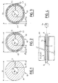
- Figures 1, 2 and 3 are sections of the sheaths fireproof G1, G2 and G3, manufactured for testing thermal insulation reviews.
- Figure 4 schematically shows an equipment allowing to carry out comparative tests of thermal insulation on the sheaths of Figures 1, 2 and 3.
- Figure 5 illustrates the results of the insulation tests thermal, carried out with the equipment of the figure 4.
- tubular G1, G2 and G3 intended to protect against metal fire fighting pipes.
- G2 and G3 ducts (see Figures 2 and 3) have flexible bodies A2 or A3, respectively superficially surrounded by a winding of E2 or E3 mesh fabric in carbonizable preoxidized fibers Montségur.
- the flexible bodies A2 and A3 are produced in the same endothermic material as that constituting the sheath G1 and the composition of which is given above.
- the fabric winding E2 of the sheath G2 is impregnated silicone, while the fabric winding E3 of the sheath G3 is impregnated with an intumescent product, for example the one marketed under the name ORGOL FS Commercial by the American Society 3M.
- the flexible bodies A1, A2 and A3 are produced by any known means, such as molding and injection.
- the windings E2 and E3 are glued to the bodies A2 and A3, for example using a silicone adhesive of the type that marketed under the trade name CAF 730 by the French company RHONE-POULENC, or joined to said bodies A2 and A3 by injection inside said preformed windings.
- the ducts G1, G2 and G3 have slots longitudinal F1, F2 or F3, intended to allow the placing said sheaths on a pipe, by elastic deformation.
- the free end L2 or L3 of the winding E2 or E3 covers the slot F2 or F3 and is not secured to the rest of said winding.
- the outside diameters D1, D2 and D3 of the ducts G1, G2 and G3 are equal to 30 mm, while the inside diameters d1, d2 and d3 respectively are equal to 10 mm.
- the result that the thickness el of the sheath G1 is equal to 10 mm.
- their body A2 and A3 have a thickness e2 or e3 of 8 mm and their windings E2 and E3 a thickness e'2 or e'3 of 2 mm.
- an apparatus comprising a tube Tu (with an outside diameter equal to 10 mm) closed at its ends by plugs B, pierced with vents v , and a temperature probe S housed inside said tube Tu and connected to a thermometer Th, on which is displayed the temperature measured by said probe S.
- the Tu tube On the Tu tube, you can put one or the other of the ducts G1, G2 and G3, by introducing said Tu tube in slot F1, F2 or F3.
- the free ends L2 and L3 are joined to the rest of the winding E2 or E3 by bonding with silicone glue, after setting in place on the Tu tube, in order to close the slots F2 or F3.
- the experimentation apparatus further includes a BR burner (symbolized by a rectangle in phantom) in FIG. 4) capable of directing on the sheath G1, G2 or G3, placed on the Tu tube, and all around of it, controlled temperature flames.
- a BR burner symbolized by a rectangle in phantom
- the curve Fi shows an example of fire applied to the sheaths G1, G2 and G3 by the burner BR.
- the temperature T of this example of fire Fi changes in one minute from room temperature to almost 900 ° C, is maintained at this temperature for about six minutes, then decreases.
- the curves K1, K2 and K3 in Figure 5 indicate the change in temperature, measured by the S probe inside the Tu tube, respectively when the ducts G1, G2 and G3 are subject to the fire example Fi.
- the temperature inside the tube You approach 450 ° C and 350 ° C, respectively.
- this temperature remains below 120 ° C.
- the curve K'3 gives the variation of the temperature inside the Tu tube for a sheath, conforming to the invention and practically identical to the G3 sheath, in which the intumescent agent permeating the coil E3 is not pure, but is mixed at 15% in weight of a silicone adhesive, intended to secure the connection of the winding E3 on the flexible body A3.
Description
La présente invention concerne un dispositif de protection antifeu, réalisé à partir d'un matériau souple à propriétés endothermiques.The present invention relates to a device for fire protection, made from a flexible material with endothermic properties.
Par le document FR-A-2 632 866, on connaít déjà un matériau de protection antifeu incorporant une charge active endothermique, telle que le borax (tétraborate disodique décahydraté). Sous l'action de la chaleur, cette charge active se décompose en libérant de l'eau, qui se vaporise à la surface dudit matériau. La vaporisation s'effectuant de façon endothermique, il en résulte un abaissement de la température superficielle dudit matériau. De plus, les propriétés intumescentes du matériau renforcent les propriétés isolantes de celui-ci pendant les agressions thermiques.By document FR-A-2 632 866, we already know a fire protection material incorporating a endothermic active charge, such as borax (tetraborate disodium decahydrate). Under the action of heat, this active charge decomposes by releasing water, which vaporizes on the surface of said material. The vaporization takes place endothermically, this results in a lowering of the temperature surface of said material. In addition, the properties intumescent of the material reinforce the properties insulating it during thermal attacks.
Lorsque, avec un tel matériau, on désire réaliser un dispositif de protection antifeu (plaque, gaine, coque, etc ...), on est confronté à la difficulté provenant du fait que, sous l'action du feu, ledit matériau peut dans certains cas se casser, de sorte que des morceaux dudit dispositif se détachent du reste de celui-ci, en réduisant ainsi la protection des objets devant être protégés du feu par ledit dispositif de protection.When, with such a material, one wishes to realize a fire protection device (plate, sheath, shell, etc ...), we are faced with the difficulty the fact that, under the action of fire, said material can in some cases break, so that pieces of said device detach from the rest of it, thus reducing the protection of objects in front be protected from fire by said protective device.
Par ailleurs, pour certaines applications, il est nécessaire d'augmenter l'effet antifeu d'un tel matériau. Pour ce faire, il apparaít avantageux de renforcer l'intumescence dudit matériau. Cependant, si l'on incorpore un agent intumescent audit matériau, on augmente la fragilité de celui-ci du fait de l'augmentation de volume de l'agent intumescent sous l'action du feu. Par ailleurs, si l'on recouvre la surface dudit matériau avec un agent intumescent, par exemple sous forme de peinture, l'adhérence dudit agent intumescent sur ledit matériau est très faible, de sorte que sous l'action du feu et/ou d'une déformation mécanique, la couche superficielle dudit agent intumescent se sépare au moins partiellement dudit dispositif de protection, laissant le matériau de ce dernier au contact direct du feu avec les effets de dégradation décrits ci-dessus.In addition, for certain applications, it is necessary to increase the fireproofing effect of such a material. To do this, it appears advantageous to strengthen intumescence of said material. However, if we incorporate an intumescent agent to said material, we increase the fragility of it due to the increase volume of the intumescent agent under the action of fire. Furthermore, if the surface of said material is covered with an intumescent agent, for example in the form of paint, the adhesion of said intumescent agent to said material is very weak, so that under the action fire and / or mechanical deformation, surface layer of said intumescent agent separates at least partially of said protection device, leaving the latter's material in direct contact fire with the degradation effects described above.
La présente invention a pour objet de remédier à ces inconvénients et de permettre la réalisation d'un dispositif de protection antifeu présentant des propriétés endothermiques et intumescentes améliorées.The object of the present invention is to remedy these disadvantages and allow the realization of a fire protection device having properties improved endothermic and intumescent.
A cette fin, selon l'invention, le dispositif de protection antifeu comportant un corps souple de matériau à propriétés endothermiques comprenant un liant de silicone et une charge libérant de la vapeur d'eau sous l'action du feu, est remarquable en ce qu'il comporte, sur au moins la face dudit corps destinée à être dirigée vers le feu, au moins une couche d'un tissu constitué de fibres résistant au feu et imprégné d'un agent intumescent.To this end, according to the invention, the protection device fire-resistant comprising a flexible body of material with endothermic properties comprising a silicone binder and a charge releasing water vapor under the action of fire, is remarkable in that it comprises, on at least the face of said body intended to be directed towards the fire, at minus a layer of a fabric made of strong fibers fire and impregnated with an intumescent agent.
Ainsi, ledit tissu sert d'armature pour l'accrochage dudit agent intumescent sur le matériau à propriétés endothermiques. L'adhérence dudit agent intumescent sur ledit matériau est donc particulièrement bonne. Par ailleurs, ledit tissu forme une armature mécanique empêchant ledit matériau à propriétés endothermiques de se détériorer, morceau par morceau. L'expérience a montré que, sous l'action du feu, le tissu imprégné de l'agent intumescent forme une coque rigide et dilatée, qui maintient le matériau endothermique sous-jacent et dont la porosité est suffisante pour être traversée par la vapeur engendrée par ledit matériau à propriétés endothermiques.Thus, said fabric serves as a framework for hanging of said intumescent agent on the material with properties endothermic. The adhesion of said intumescent agent on said material is therefore particularly good. Furthermore, said fabric forms a frame mechanical preventing said material with endothermic properties to deteriorate, piece by piece. Experience has shown that, under the action of fire, the tissue impregnated with the intumescent agent forms a rigid and expanded shell, which holds the endothermic material underlying and with sufficient porosity to be crossed by the generated vapor by said material with endothermic properties.
Le tissu sert donc, simultanément, à l'accrochage de l'agent intumescent sur le matériau endothermique et au maintien de l'intégrité de ce dernier, tout en permettant le dégagement de la vapeur engendrée par ledit matériau endothermique.The fabric is therefore used simultaneously for hanging intumescent agent on the endothermic material and maintaining the integrity of the latter, while allowing the release of the generated vapor by said endothermic material.
De préférence, le tissu, utilisé dans la mise en oeuvre de la présente invention, est réalisé en fibres organiques préoxydées carbonisables, capables d'absorber fortement le flux thermique infrarouge d'un incendie. Un tel tissu est de préférence du type à mailles pour présenter de grandes propriétés d'élasticité susceptibles de permettre le gonflement de l'agent intumescent, et lesdites fibres organiques peuvent être à base de polyacrylonitdle. D'autres fibres, telles que des fibres aramides, peuvent être prévues pour faciliter le tissage. De tels tissus sont par exemple fabriqués et vendus, sous le nom commercial MONTSEGUR, par la Société Arlégeoise de Bonneterie, 09300 Montferrier, France.Preferably, the fabric used in the implementation work of the present invention, is made of fibers carbonizable pre-oxidized organic, capable strongly absorb infrared heat flow of a fire. Such a fabric is preferably of the type with mesh to exhibit great elasticity properties likely to allow the swelling of the intumescent agent, and said organic fibers may be based on polyacrylonitdle. Other fibers, such as aramid fibers, may be provided to facilitate weaving. Such fabrics are by example manufactured and sold under the trade name MONTSEGUR, by the Société Arlégeoise de Bonneterie, 09300 Montferrier, France.
Avantageusement, ledit agent intumescent se présente, avant imprégnation dudit tissu, sous la forme d'un liquide aqueux et, après imprégnation et séchage, sous la forme d'un revêtement souple. Ainsi, ledit agent intumescent ne peut dégager de vapeurs toxiques sous l'action du feu.Advantageously, said intumescent agent is present, before impregnation of said fabric, in the form of an aqueous liquid and, after impregnation and drying, in the form of a flexible coating. So, said intumescent agent cannot release vapors toxic by fire.
Un tel agencement intumescent peut être celui fabriqué et vendu, sous le nom commercial ORGOL FS, par la Société 3M, 95006 Cergy-Pontoise Cedex, France.Such an intumescent arrangement can be the one made and sold under the trade name ORGOL FS, by the company 3M, 95006 Cergy-Pontoise Cedex, France.
Pour réaliser le dispositif de protection antifeu conforme à la présente invention, on peut, séparément fabriquer le corps du matériau souple à propriétés endothermiques et préparer le tissu imprégné par l'agent intumescent, puis solidariser celui-ci sur ledit corps. Une telle solidarisation est de préférence réalisée par une colle silicone, par exemple celle connue sous le nom commercial CAF 730, fabriquée et vendue parla Société française RHONE-POULENC. Une telle colle silicone est avantageuse, car elle polymérise en présence d'eau, et donc en présence de l'agent intumescent aqueux préféré.To make the fire protection device according to the present invention, it is possible, separately manufacture the body of flexible material with properties endothermic and prepare the fabric impregnated with the intumescent agent, then secure it on said body. Such joining is preferably carried out with a silicone adhesive, for example that known under the trade name CAF 730, manufactured and sold by the French company RHONE-POULENC. A such silicone glue is advantageous because it polymerizes in the presence of water, and therefore in the presence of the preferred aqueous intumescent agent.
La colle silicone peut être appliquée entre le corps du matériau à propriétés endothermiques et le tissu imprégné de l'agent intumescent. Elle peut également être mélangée audit agent intumescent avant imprégnation dudit tissu. Dans ce dernier cas, l'imprégnation dudit tissu se fait avec un mélange d'agent intumescent et de colle silicone comportant au moins 15% en poids de colle silicone.Silicone glue can be applied between the material body with endothermic properties and the tissue impregnated with the intumescent agent. She can also be mixed with said intumescent agent before impregnation of said fabric. In the latter case, the impregnation said fabric is made with a mixture of intumescent agent and silicone glue comprising at least 15% by weight of silicone glue.
En variante, le dispositif de protection antifeu conforme à la présente invention pourrait être obtenu par moulage du corps en matériau souple à propriétés endothermiques sur ledit tissu imprégné par l'agent intumescent, de préférence mélangé à ladite colle silicone.Alternatively, the fire protection device according to the present invention could be obtained by molding the body of flexible material with properties endothermic on said tissue impregnated with the agent intumescent, preferably mixed with said silicone adhesive.
Avantageusement, la charge, incorporée audit matériau à propriétés endothermiques et libérant de la vapeur d'eau sous l'action du feu, est du phosphate trisodique à 12 molécules d'eau.Advantageously, the load, incorporated into said audit material with endothermic properties and releasing water vapor under the action of fire, is phosphate trisodium to 12 molecules of water.
Pour que ledit corps puisse être facilement moulé à la forme désirée (plaque, coque, gaine, tube, etc ...), ledit matériau comporte de façon connue un liant de silicone. De plus, une charge de renforcement réfractaire, compatible avec ledit liant de silicone, peut être prévue.So that said body can be easily molded to the desired shape (plate, shell, sheath, tube, etc ...), said material comprises in known manner a silicone binder. In addition, a strengthening charge refractory, compatible with said silicone binder, can be expected.
Une composition préférée pour le matériau dudit corps souple est la suivante :
- liant élastomère de silicone, de préférence celui portant la référence RTV 141 de la Société RHONE-POULENC 100 parties en poids
- charge de renforcement réfractaire, de préférence
du
TiO2 7 parties en poids - charge endothermique, à savoir du phosphate trisodique à 12 molécules d'eau 110 parties en poids
- catalyseur du liant élastomère de
silicone 10 parties en poids
- silicone elastomer binder, preferably that bearing the reference RTV 141 from the company RHONE-POULENC 100 parts by weight
- refractory reinforcing filler, preferably
TiO2 7 parts by weight - endothermic charge, namely trisodium phosphate containing 12 water molecules 110 parts by weight
- silicone
elastomer binder catalyst 10 parts by weight
Pour montrer l'efficacité antifeu du dispositif de protection conforme à la présente invention, on a fabriqué des gaines tubulaires G1, G2 et G3 pour la protection de conduites, dont seule la gaine G3 est conforme à la présente invention, et on a procédé à des essais comparatifs.To show the fire-fighting efficiency of the protection according to the present invention, we manufactured G1, G2 and G3 tubular sheaths for protection of pipes, of which only the sheath G3 is according to the present invention, and we proceeded to comparative tests.
Les figures annexées sont destinées à illustrer ces essais.The attached figures are intended to illustrate these tests.
Les figures 1, 2 et 3 sont des coupes des gaines antifeu G1, G2 et G3, fabriquées en vue d'essais comparatifs d'isolation thermique.Figures 1, 2 and 3 are sections of the sheaths fireproof G1, G2 and G3, manufactured for testing thermal insulation reviews.
La figure 4 montre schématiquement un équipement permettant de réaliser les essais comparatifs d'isolation thermique sur les gaines des figures 1, 2 et 3.Figure 4 schematically shows an equipment allowing to carry out comparative tests of thermal insulation on the sheaths of Figures 1, 2 and 3.
La figure 5 illustre les résultats des essais d'isolation thermique, menés avec l'équipement de la figure 4.Figure 5 illustrates the results of the insulation tests thermal, carried out with the equipment of the figure 4.
Comme l'illustrent en section les figures 1, 2 et 3, à des fins d'essais comparatifs, on réalise trois gaines tubulaires G1, G2 et G3, destinées à protéger des conduites métalliques contre l'incendie.As illustrated in section Figures 1, 2 and 3, for the purposes of comparative tests, three sheaths are produced tubular G1, G2 and G3, intended to protect against metal fire fighting pipes.
La gaine G1 (voir la figure 1) est constituée uniquement d'un corps A1 de matière endothermique souple, dont la composition est par exemple la suivante :
- élastomère de silicone RTV 141 100 parties en poids
TiO2 7 parties en poids- phosphate trisodique à 12 molécules d'eau 110 parties en poids
- catalyseur de l'élastomère de
silicone 10 parties en poids
- RTV 141
silicone elastomer 100 parts by weight -
TiO2 7 parts by weight - trisodium phosphate containing 12 water molecules 110 parts by weight
-
silicone elastomer catalyst 10 parts by weight
Les gaines G2 et G3 (voir les figures 2 et 3) comportent des corps souples A2 ou A3, respectivement entourés superficiellement d'un enroulement de tissu à mailles E2 ou E3 en fibres préoxydées carbonisables Montségur.G2 and G3 ducts (see Figures 2 and 3) have flexible bodies A2 or A3, respectively superficially surrounded by a winding of E2 or E3 mesh fabric in carbonizable preoxidized fibers Montségur.
Les corps souples A2 et A3 sont réalisés dans la même matière endothermique que celle constituant la gaine G1 et dont la composition est donnée ci-dessus.The flexible bodies A2 and A3 are produced in the same endothermic material as that constituting the sheath G1 and the composition of which is given above.
L'enroulement de tissu E2 de la gaine G2 est imprégné de silicone, alors que l'enroulement de tissu E3 de la gaine G3 est imprégné d'un produit intumescent, par exemple celui commercialisé sous le nom commercial ORGOL FS par la Société américaine 3M.The fabric winding E2 of the sheath G2 is impregnated silicone, while the fabric winding E3 of the sheath G3 is impregnated with an intumescent product, for example the one marketed under the name ORGOL FS Commercial by the American Society 3M.
Les corps souples A1, A2 et A3 sont réalisés par tout moyen connu, tel que moulage et injection. Les enroulements E2 et E3 sont collés sur les corps A2 et A3, par exemple à l'aide d'une colle silicone du type de celle commercialisée sous le nom commercial CAF 730 par la Société française RHONE-POULENC, ou bien solidarisés desdits corps A2 et A3 par injection à l'intérieur desdits enroulements préformés.The flexible bodies A1, A2 and A3 are produced by any known means, such as molding and injection. The windings E2 and E3 are glued to the bodies A2 and A3, for example using a silicone adhesive of the type that marketed under the trade name CAF 730 by the French company RHONE-POULENC, or joined to said bodies A2 and A3 by injection inside said preformed windings.
Les gaines G1, G2 et G3 comportent des fentes longitudinales F1, F2 ou F3, destinées à permettre la mise en place desdites gaines sur une conduite, par déformation élastique. L'extrémité libre L2 ou L3 de l'enroulement E2 ou E3 recouvre la fente F2 ou F3 et n'est pas solidarisée du reste dudit enroulement.The ducts G1, G2 and G3 have slots longitudinal F1, F2 or F3, intended to allow the placing said sheaths on a pipe, by elastic deformation. The free end L2 or L3 of the winding E2 or E3 covers the slot F2 or F3 and is not secured to the rest of said winding.
Dans les exemples considérés, les diamètres extérieurs D1, D2 et D3 des gaines G1, G2 et G3 sont égaux à 30 mm, tandis que les diamètres intérieurs d1, d2 et d3 respectifs sont égaux à 10 mm. Il en résulte que l'épaisseur el de la gaine G1 est égale à 10 mm. En ce qui concerne les gaines G2 et G3, leurs corps A2 et A3 ont une épaisseur e2 ou e3 de 8 mm et leurs enroulements E2 et E3 une épaisseur e'2 ou e'3 de 2 mm.In the examples considered, the outside diameters D1, D2 and D3 of the ducts G1, G2 and G3 are equal to 30 mm, while the inside diameters d1, d2 and d3 respectively are equal to 10 mm. The result that the thickness el of the sheath G1 is equal to 10 mm. With regard to the G2 and G3 ducts, their body A2 and A3 have a thickness e2 or e3 of 8 mm and their windings E2 and E3 a thickness e'2 or e'3 of 2 mm.
Pour tester les gaines G1, G2 et G3, on dispose d'un appareil (voir la figure 4) comportant un tube Tu (de diamètre extérieur égal à 10 mm) obturé à ses extrémités par des bouchons B, percés d'évents v, et une sonde de température S logée à l'intérieur dudit tube Tu et reliée à un thermomètre Th, sur lequel est affichée la température mesurée par ladite sonde S.To test the ducts G1, G2 and G3, there is an apparatus (see FIG. 4) comprising a tube Tu (with an outside diameter equal to 10 mm) closed at its ends by plugs B, pierced with vents v , and a temperature probe S housed inside said tube Tu and connected to a thermometer Th, on which is displayed the temperature measured by said probe S.
Sur le tube Tu, on peut mettre en place l'une ou l'autre des gaines G1, G2 et G3, en introduisant ledit tube Tu dans la fente F1, F2 ou F3. En ce qui concerne les gaines G2 et G3, les extrémités libres L2 et L3 sont solidarisées du reste de l'enroulement E2 ou E3 par collage à l'aide d'une colle au silicone, après mise en place sur le tube Tu, afin d'obturer les fentes F2 ou F3.On the Tu tube, you can put one or the other of the ducts G1, G2 and G3, by introducing said Tu tube in slot F1, F2 or F3. In regards to the ducts G2 and G3, the free ends L2 and L3 are joined to the rest of the winding E2 or E3 by bonding with silicone glue, after setting in place on the Tu tube, in order to close the slots F2 or F3.
L'appareil d'expérimentation comporte de plus un brûleur BR (symbolisé par un rectangle en trait mixte sur la figure 4) susceptible de diriger sur la gaine G1, G2 ou G3, mise en place sur le tube Tu, et tout autour de celle-ci, des flammes à température contrôlée.The experimentation apparatus further includes a BR burner (symbolized by a rectangle in phantom) in FIG. 4) capable of directing on the sheath G1, G2 or G3, placed on the Tu tube, and all around of it, controlled temperature flames.
Sur la figure 5 (dont l'axe des abscisses porte le temps t en minutes, et dont l'axe des ordonnés porte les températures en degrés centigrades), on a représenté par la courbe Fi un exemple de feu appliqué aux gaines G1, G2 et G3 par le brûleur BR. Comme on peut le voir, la température T de cet exemple de feu Fi passe en une minute de la température ambiante à près de 900°C, se maintient à cette température pendant environ six minutes, puis décroít.In FIG. 5 (whose abscissa axis carries the time t in minutes, and whose ordinate axis carries the temperatures in degrees centigrade), the curve Fi shows an example of fire applied to the sheaths G1, G2 and G3 by the burner BR. As we can see, the temperature T of this example of fire Fi changes in one minute from room temperature to almost 900 ° C, is maintained at this temperature for about six minutes, then decreases.
Les courbes K1, K2 et K3 de la figure 5 indiquent l'évolution de la température, mesurée par la sonde S à l'intérieur du tube Tu, respectivement lorsque les gaines G1, G2 et G3 sont soumises à l'exemple de feu Fi. Comme on peut le voir, avec les gaines G1 et G2, la température à l'intérieur du tube Tu s'approche de 450°C et 350°C, respectivement. En revanche, avec la gaine G3 conforme à l'invention, cette température reste inférieure à 120°C.The curves K1, K2 and K3 in Figure 5 indicate the change in temperature, measured by the S probe inside the Tu tube, respectively when the ducts G1, G2 and G3 are subject to the fire example Fi. As we can see, with the G1 and G2 sheaths, the temperature inside the tube You approach 450 ° C and 350 ° C, respectively. However, with the sheath G3 according to the invention, this temperature remains below 120 ° C.
La courbe K'3 donne la variation de la température à l'intérieur du tube Tu pour une gaine, conforme à l'invention et pratiquement identique à la gaine G3, dans laquelle l'agent intumescent imprégnant l'enroulement E3 n'est pas pur, mais est mélangé à 15% en poids d'une colle silicone, destinée à assurer la solidarisation de l'enroulement E3 sur le corps souple A3.The curve K'3 gives the variation of the temperature inside the Tu tube for a sheath, conforming to the invention and practically identical to the G3 sheath, in which the intumescent agent permeating the coil E3 is not pure, but is mixed at 15% in weight of a silicone adhesive, intended to secure the connection of the winding E3 on the flexible body A3.
On voit que l'incorporation de la colle silicone à l'agent intumescent imprégnant l'enroulement E3 (courbe K'3) est moins avantageuse que l'imprégnation de l'enroulement E3 avec l'agent intumescent pur, suivie du collage dudit enroulement sur le corps souple A3 (courbe K3). Toutefois, même dans ce cas moins avantageux, la température à l'intérieur du tube Tu ne dépasse pas 150°C, ce qui est à comparer avec les températures maximales atteintes par les courbes K1 et K2.We see that the incorporation of silicone glue the intumescent agent permeating the winding E3 (curve K'3) is less advantageous than impregnation of winding E3 with the intumescent agent pure, followed by bonding of said winding to the body flexible A3 (curve K3). However, even in this case less advantageous, the temperature inside the tube You do not exceed 150 ° C, which is to compare with the maximum temperatures reached by the curves K1 and K2.
Claims (10)
- Device for protection against fire (G3), comprising a flexible body (A3) of material with endothermic properties comprising a silicone binder and a filler releasing water vapour under the effect of heat, characterized in that it comprises, on at least that face of the said body which is intended to be directed towards the fire, at least one layer (E3) of a fabric consisting of fire-resistant fibres and impregnated with an intumescent agent and in that the said impregnated fabric, when subjected to the effect of fire, exhibits a sufficient porosity to allow the vapour generated by the said material with endothermic properties to pass through.
- Device according to Claim 1, characterized in that the said fabric is made of carbonizable preoxidized organic fibres.
- Device according to Claim 2, characterized in that the said fabric is of the meshed type.
- Device according to one of Claims 1 to 3, characterized in that, before impregnation of the said fabric, the said intumescent agent is in the form of an aqueous liquid and, after impregnation and drying, in the form of a flexible coating.
- Device according to one of Claims 1 to 4, characterized in that the said fabric is integrally joined to the body by adhesive bonding with the aid of a silicone adhesive.
- Device according to Claims 4 and 5, characterized in that the said silicone adhesive polymerizes in the presence of water.
- Device according to either of Claims 5 and 6, characterized in that the said silicone adhesive is mixed with the said intumescent agent before impregnation of the said fabric.
- Device according to one of Claims 1 to 7, characterized in that the said filler releasing water vapour under the effect of fire is trisodium phosphate containing 12 molecules of water.
- Device according to one of Claims 1 to 8, characterized in that the said flexible body comprises a reinforcing refractory filler.
- Device according to one of Claims 1 to 9, characterized in that the composition of the material of the said flexible body is the following:silicone elastomer binder 100 parts by weightTiO2 (reinforcing refractory filler) 7 parts by weighttrisodium phosphate containing 12 molecules of water 110 parts by weightcatalyst for the elastomer binder 10 parts by weight.
Applications Claiming Priority (2)
| Application Number | Priority Date | Filing Date | Title |
|---|---|---|---|
| FR9207745 | 1992-06-24 | ||
| FR9207745A FR2692794B1 (en) | 1992-06-24 | 1992-06-24 | FIRE PROTECTION DEVICE IN FLEXIBLE ENDOTHERMIC MATERIAL. |
Publications (2)
| Publication Number | Publication Date |
|---|---|
| EP0576321A1 EP0576321A1 (en) | 1993-12-29 |
| EP0576321B1 true EP0576321B1 (en) | 1999-09-08 |
Family
ID=9431138
Family Applications (1)
| Application Number | Title | Priority Date | Filing Date |
|---|---|---|---|
| EP93401488A Expired - Lifetime EP0576321B1 (en) | 1992-06-24 | 1993-06-10 | Fire-proof protecting device comprising a flexible endothermic material |
Country Status (6)
| Country | Link |
|---|---|
| US (1) | US5378530A (en) |
| EP (1) | EP0576321B1 (en) |
| JP (1) | JP3297149B2 (en) |
| CA (1) | CA2098765A1 (en) |
| DE (1) | DE69326288D1 (en) |
| FR (1) | FR2692794B1 (en) |
Families Citing this family (11)
| Publication number | Priority date | Publication date | Assignee | Title |
|---|---|---|---|---|
| US5681640A (en) * | 1995-10-27 | 1997-10-28 | Flame Seal Products, Inc. | Passive fire protection systems for conduit, cable trays, support rods, and structural steel |
| CA2271229C (en) * | 1999-05-07 | 2007-09-25 | 3M Innovative Properties Company | Novel fire stop and its use |
| US20050051345A1 (en) * | 2000-02-14 | 2005-03-10 | Walter Kidde Portable Equipment, Inc. | Fire blanket |
| CN1217720C (en) * | 2000-02-14 | 2005-09-07 | 沃尔特基德轻便装置公司 | Fire blanket |
| US6820382B1 (en) | 2000-05-03 | 2004-11-23 | 3M Innovative Properties Company | Fire stop and its use |
| DE102005033991B4 (en) * | 2005-07-21 | 2018-10-11 | Aik Flammadur Brandschutz Gmbh | Fire protection system for several supply lines held on a route or platform |
| US20070100368A1 (en) | 2005-10-31 | 2007-05-03 | Quijano Rodolfo C | Intragastric space filler |
| DE102006037274B4 (en) * | 2006-08-09 | 2017-11-02 | Airbus Operations Gmbh | Fire-retardant cable routing for electrical cables in fire-hazard areas in aircraft |
| WO2011011743A2 (en) | 2009-07-23 | 2011-01-27 | Reshape Medical, Inc. | Deflation and removal of implantable medical devices |
| WO2011127205A1 (en) | 2010-04-06 | 2011-10-13 | Reshape Medical , Inc. | Inflation devices for intragastric devices with improved attachment and detachment and associated systems and methods |
| US20120067614A1 (en) * | 2010-09-21 | 2012-03-22 | General Cable Technologies Corporation | Cable with a split tube and method for making the same |
Family Cites Families (6)
| Publication number | Priority date | Publication date | Assignee | Title |
|---|---|---|---|---|
| GB1497659A (en) * | 1974-11-14 | 1978-01-12 | Tsi Inc | Thermal protecting process and composition |
| US4273821A (en) * | 1978-01-27 | 1981-06-16 | Pedlow J Watson | Fire protective tape |
| DE2905610A1 (en) * | 1979-02-14 | 1980-08-28 | Gummi Reischl Inh Peter Reisch | Fireproof hose with inner synthetic rubber tube - has tube coated with rubber adhesive layer in which is embedded woven fabric covered with fireproof layer |
| GB2120580A (en) * | 1982-05-26 | 1983-12-07 | Rolls Royce | Intumescent paint layers |
| FR2632866B1 (en) * | 1988-06-16 | 1990-11-16 | Aerospatiale | FIRE PROTECTION MATERIAL |
| US5091243A (en) * | 1989-04-04 | 1992-02-25 | Springs Industries, Inc. | Fire barrier fabric |
-
1992
- 1992-06-24 FR FR9207745A patent/FR2692794B1/en not_active Expired - Lifetime
-
1993
- 1993-06-10 EP EP93401488A patent/EP0576321B1/en not_active Expired - Lifetime
- 1993-06-10 DE DE69326288T patent/DE69326288D1/en not_active Expired - Lifetime
- 1993-06-16 US US08/079,080 patent/US5378530A/en not_active Expired - Fee Related
- 1993-06-18 CA CA002098765A patent/CA2098765A1/en not_active Withdrawn
- 1993-06-24 JP JP15371093A patent/JP3297149B2/en not_active Expired - Fee Related
Also Published As
| Publication number | Publication date |
|---|---|
| DE69326288D1 (en) | 1999-10-14 |
| FR2692794B1 (en) | 1997-01-10 |
| US5378530A (en) | 1995-01-03 |
| EP0576321A1 (en) | 1993-12-29 |
| JP3297149B2 (en) | 2002-07-02 |
| JPH0657846A (en) | 1994-03-01 |
| FR2692794A1 (en) | 1993-12-31 |
| CA2098765A1 (en) | 1993-12-25 |
Similar Documents
| Publication | Publication Date | Title |
|---|---|---|
| EP0576321B1 (en) | Fire-proof protecting device comprising a flexible endothermic material | |
| EP0073688B1 (en) | Protecting or dissipating thermal screen | |
| FR2698153A1 (en) | Multi-layer pipe for combustible fluids - has outer self-extinguishing layer, intermediate layer resistant to high temperatures, and inner plastic layer | |
| WO1986004018A1 (en) | Fire-resistant cowls, particularly for aircraft engines | |
| EP0283385A1 (en) | Covering for the thermal protection of a structure subject to intense thermal stresses | |
| WO2008049703A1 (en) | Fire-proof cover | |
| CA2979421C (en) | Method and device for fireproofing a composite material part | |
| BE1012736A6 (en) | Thermal insulation and sound. | |
| EP0612540B1 (en) | Supple device having fire-damping properties | |
| EP0660020B1 (en) | Manufacturing process for a fire protection on the base of silicone and fire protection | |
| WO1996032161A1 (en) | Flexible device having fire-resistant properties | |
| EP0035417A1 (en) | Product and processes for making fire-proofed gaskets, and device for making one of these processes | |
| BE1003845A4 (en) | Building element with a coating fire-based impregnated paper mica. | |
| EP0230831B1 (en) | Product for the instantaneous use as a thermal protection or dissipation screen | |
| FR2796443A1 (en) | FIRE-RESISTANT INSULATING MATERIAL, SUITABLE FOR AERONAUTICAL INSULATION, METHOD AND DEVICE FOR MANUFACTURING SAME | |
| FR2632051A1 (en) | Coating for protection against fire and heat | |
| EP3497183B1 (en) | Flexible part with fire protection properties | |
| EP0473487A1 (en) | High performance heat screens | |
| EP0296027A1 (en) | Fire proofed fabric layer | |
| FR2628507A1 (en) | Linings and sheaths for pipes - made from resin coated heat treated knitted yarn fabric of glass, carbon, polyester fibres, etc. | |
| EP2386005A1 (en) | Composite device for heat insulation, particularly for fireproofing or fire resistance | |
| WO1996001347A1 (en) | Moulded article for fire protection | |
| BE1007654A3 (en) | Method and device for producing a sealing membrane. | |
| FR2796444A1 (en) | Fireproof thermal and sound insulating material for aircraft fuselage, etc. has fibrous insulating layer(s) and fireproof mineral wool layer(s) | |
| LU83374A1 (en) | FIRE-RESISTANT FOR THE PASSAGE OF AT LEAST ONE HOLLOW ELEMENT THROUGH A WALL OF A BUILDING |
Legal Events
| Date | Code | Title | Description |
|---|---|---|---|
| PUAI | Public reference made under article 153(3) epc to a published international application that has entered the european phase |
Free format text: ORIGINAL CODE: 0009012 |
|
| AK | Designated contracting states |
Kind code of ref document: A1 Designated state(s): BE DE ES GB IT NL |
|
| 17P | Request for examination filed |
Effective date: 19940208 |
|
| 17Q | First examination report despatched |
Effective date: 19951215 |
|
| APAB | Appeal dossier modified |
Free format text: ORIGINAL CODE: EPIDOS NOAPE |
|
| APAD | Appeal reference recorded |
Free format text: ORIGINAL CODE: EPIDOS REFNE |
|
| APAB | Appeal dossier modified |
Free format text: ORIGINAL CODE: EPIDOS NOAPE |
|
| GRAG | Despatch of communication of intention to grant |
Free format text: ORIGINAL CODE: EPIDOS AGRA |
|
| GRAH | Despatch of communication of intention to grant a patent |
Free format text: ORIGINAL CODE: EPIDOS IGRA |
|
| GRAH | Despatch of communication of intention to grant a patent |
Free format text: ORIGINAL CODE: EPIDOS IGRA |
|
| GRAA | (expected) grant |
Free format text: ORIGINAL CODE: 0009210 |
|
| AK | Designated contracting states |
Kind code of ref document: B1 Designated state(s): BE DE ES GB IT NL |
|
| PG25 | Lapsed in a contracting state [announced via postgrant information from national office to epo] |
Ref country code: NL Free format text: LAPSE BECAUSE OF FAILURE TO SUBMIT A TRANSLATION OF THE DESCRIPTION OR TO PAY THE FEE WITHIN THE PRESCRIBED TIME-LIMIT Effective date: 19990908 Ref country code: IT Free format text: LAPSE BECAUSE OF FAILURE TO SUBMIT A TRANSLATION OF THE DESCRIPTION OR TO PAY THE FEE WITHIN THE PRE;WARNING: LAPSES OF ITALIAN PATENTS WITH EFFECTIVE DATE BEFORE 2007 MAY HAVE OCCURRED AT ANY TIME BEFORE 2007. THE CORRECT EFFECTIVE DATE MAY BE DIFFERENT FROM THE ONE RECORDED.SCRIBED TIME-LIMIT Effective date: 19990908 Ref country code: GB Free format text: LAPSE BECAUSE OF FAILURE TO SUBMIT A TRANSLATION OF THE DESCRIPTION OR TO PAY THE FEE WITHIN THE PRESCRIBED TIME-LIMIT Effective date: 19990908 Ref country code: ES Free format text: THE PATENT HAS BEEN ANNULLED BY A DECISION OF A NATIONAL AUTHORITY Effective date: 19990908 |
|
| REF | Corresponds to: |
Ref document number: 69326288 Country of ref document: DE Date of ref document: 19991014 |
|
| PG25 | Lapsed in a contracting state [announced via postgrant information from national office to epo] |
Ref country code: DE Free format text: LAPSE BECAUSE OF FAILURE TO SUBMIT A TRANSLATION OF THE DESCRIPTION OR TO PAY THE FEE WITHIN THE PRESCRIBED TIME-LIMIT Effective date: 19991209 |
|
| NLV1 | Nl: lapsed or annulled due to failure to fulfill the requirements of art. 29p and 29m of the patents act | ||
| GBV | Gb: ep patent (uk) treated as always having been void in accordance with gb section 77(7)/1977 [no translation filed] |
Effective date: 19990908 |
|
| PG25 | Lapsed in a contracting state [announced via postgrant information from national office to epo] |
Ref country code: BE Free format text: LAPSE BECAUSE OF NON-PAYMENT OF DUE FEES Effective date: 20000630 |
|
| PLBE | No opposition filed within time limit |
Free format text: ORIGINAL CODE: 0009261 |
|
| STAA | Information on the status of an ep patent application or granted ep patent |
Free format text: STATUS: NO OPPOSITION FILED WITHIN TIME LIMIT |
|
| 26N | No opposition filed | ||
| BERE | Be: lapsed |
Owner name: AEROSPATIALE SOC. NATIONALE INDUSTRIELLE Effective date: 20000630 |
|
| APAH | Appeal reference modified |
Free format text: ORIGINAL CODE: EPIDOSCREFNO |