EP0575255A1 - Fastening device of a tubular profile with a part of complementary structure - Google Patents
Fastening device of a tubular profile with a part of complementary structure Download PDFInfo
- Publication number
- EP0575255A1 EP0575255A1 EP93401559A EP93401559A EP0575255A1 EP 0575255 A1 EP0575255 A1 EP 0575255A1 EP 93401559 A EP93401559 A EP 93401559A EP 93401559 A EP93401559 A EP 93401559A EP 0575255 A1 EP0575255 A1 EP 0575255A1
- Authority
- EP
- European Patent Office
- Prior art keywords
- chamber
- movable element
- profile
- dowel
- section
- Prior art date
- Legal status (The legal status is an assumption and is not a legal conclusion. Google has not performed a legal analysis and makes no representation as to the accuracy of the status listed.)
- Withdrawn
Links
- 230000000295 complement effect Effects 0.000 title claims abstract description 11
- 230000000694 effects Effects 0.000 claims abstract description 5
- 210000003423 ankle Anatomy 0.000 claims description 11
- 230000000712 assembly Effects 0.000 abstract description 4
- 238000000429 assembly Methods 0.000 abstract description 4
- 238000004026 adhesive bonding Methods 0.000 description 2
- 238000003466 welding Methods 0.000 description 2
- 230000007547 defect Effects 0.000 description 1
- 230000002950 deficient Effects 0.000 description 1
- 238000010586 diagram Methods 0.000 description 1
- 238000000034 method Methods 0.000 description 1
- 230000000750 progressive effect Effects 0.000 description 1
- 230000001681 protective effect Effects 0.000 description 1
- 238000000926 separation method Methods 0.000 description 1
Images

Classifications
-
- F—MECHANICAL ENGINEERING; LIGHTING; HEATING; WEAPONS; BLASTING
- F16—ENGINEERING ELEMENTS AND UNITS; GENERAL MEASURES FOR PRODUCING AND MAINTAINING EFFECTIVE FUNCTIONING OF MACHINES OR INSTALLATIONS; THERMAL INSULATION IN GENERAL
- F16B—DEVICES FOR FASTENING OR SECURING CONSTRUCTIONAL ELEMENTS OR MACHINE PARTS TOGETHER, e.g. NAILS, BOLTS, CIRCLIPS, CLAMPS, CLIPS OR WEDGES; JOINTS OR JOINTING
- F16B7/00—Connections of rods or tubes, e.g. of non-circular section, mutually, including resilient connections
- F16B7/02—Connections of rods or tubes, e.g. of non-circular section, mutually, including resilient connections with conical parts
- F16B7/025—Connections of rods or tubes, e.g. of non-circular section, mutually, including resilient connections with conical parts with the expansion of an element inside the tubes due to axial movement towards a wedge or conical element
-
- F—MECHANICAL ENGINEERING; LIGHTING; HEATING; WEAPONS; BLASTING
- F16—ENGINEERING ELEMENTS AND UNITS; GENERAL MEASURES FOR PRODUCING AND MAINTAINING EFFECTIVE FUNCTIONING OF MACHINES OR INSTALLATIONS; THERMAL INSULATION IN GENERAL
- F16B—DEVICES FOR FASTENING OR SECURING CONSTRUCTIONAL ELEMENTS OR MACHINE PARTS TOGETHER, e.g. NAILS, BOLTS, CIRCLIPS, CLAMPS, CLIPS OR WEDGES; JOINTS OR JOINTING
- F16B9/00—Connections of rods or tubular parts to flat surfaces at an angle
- F16B9/05—Connections of rods or tubular parts to flat surfaces at an angle by way of an intermediate member
- F16B9/054—Connections of rods or tubular parts to flat surfaces at an angle by way of an intermediate member the intermediate member being threaded
-
- F—MECHANICAL ENGINEERING; LIGHTING; HEATING; WEAPONS; BLASTING
- F16—ENGINEERING ELEMENTS AND UNITS; GENERAL MEASURES FOR PRODUCING AND MAINTAINING EFFECTIVE FUNCTIONING OF MACHINES OR INSTALLATIONS; THERMAL INSULATION IN GENERAL
- F16B—DEVICES FOR FASTENING OR SECURING CONSTRUCTIONAL ELEMENTS OR MACHINE PARTS TOGETHER, e.g. NAILS, BOLTS, CIRCLIPS, CLAMPS, CLIPS OR WEDGES; JOINTS OR JOINTING
- F16B2/00—Friction-grip releasable fastenings
- F16B2/02—Clamps, i.e. with gripping action effected by positive means other than the inherent resistance to deformation of the material of the fastening
- F16B2/14—Clamps, i.e. with gripping action effected by positive means other than the inherent resistance to deformation of the material of the fastening using wedges
-
- F—MECHANICAL ENGINEERING; LIGHTING; HEATING; WEAPONS; BLASTING
- F16—ENGINEERING ELEMENTS AND UNITS; GENERAL MEASURES FOR PRODUCING AND MAINTAINING EFFECTIVE FUNCTIONING OF MACHINES OR INSTALLATIONS; THERMAL INSULATION IN GENERAL
- F16B—DEVICES FOR FASTENING OR SECURING CONSTRUCTIONAL ELEMENTS OR MACHINE PARTS TOGETHER, e.g. NAILS, BOLTS, CIRCLIPS, CLAMPS, CLIPS OR WEDGES; JOINTS OR JOINTING
- F16B13/00—Dowels or other devices fastened in walls or the like by inserting them in holes made therein for that purpose
- F16B13/12—Separate metal or non-separate or non-metal dowel sleeves fastened by inserting the screw, nail or the like
- F16B13/124—Separate metal or non-separate or non-metal dowel sleeves fastened by inserting the screw, nail or the like fastened by inserting a threaded element, e.g. screw or bolt
-
- F—MECHANICAL ENGINEERING; LIGHTING; HEATING; WEAPONS; BLASTING
- F16—ENGINEERING ELEMENTS AND UNITS; GENERAL MEASURES FOR PRODUCING AND MAINTAINING EFFECTIVE FUNCTIONING OF MACHINES OR INSTALLATIONS; THERMAL INSULATION IN GENERAL
- F16B—DEVICES FOR FASTENING OR SECURING CONSTRUCTIONAL ELEMENTS OR MACHINE PARTS TOGETHER, e.g. NAILS, BOLTS, CIRCLIPS, CLAMPS, CLIPS OR WEDGES; JOINTS OR JOINTING
- F16B7/00—Connections of rods or tubes, e.g. of non-circular section, mutually, including resilient connections
- F16B7/18—Connections of rods or tubes, e.g. of non-circular section, mutually, including resilient connections using screw-thread elements
-
- F16B9/026—
Definitions
- the present invention relates to profile assembly systems for producing protective or wall support assemblies of the ramps, handrails, grab bars or the like type.
- such assemblies consist of several sections of sections which are joined to one another by welding or gluing or else associated by means of rings which are fitted on the respective ends of two sections arranged in the extension of one of the other.
- a tube assembly system is known by means of hollow cylindrical fittings having a longitudinal slot so as to allow radial expansion of said fittings when they are introduced into said pipes, this so that they can come to bear against the wall of the latter, this expansion resulting from the presence of a connecting element having the form of a threaded rod which is inserted into said fittings.
- Such a system requires the use of a threaded rod whose length is relatively large and in any event substantially double that of a fitting in order to ensure close and permanent contact between the entire surface of the fittings. associated and the internal wall of said tubes. Otherwise, that is to say with a connecting rod of shorter length, there is a loosening of the assembly, due to the appearance of a creep phenomenon on the portion of the fittings which n 'is not held by the connecting rod.
- the device, object of the present invention makes it possible to avoid the drawbacks inherent in the systems of the prior art which have just been mentioned.
- the subject of the invention is a device for assembling a tubular profile with a piece of complementary structure, said device conventionally comprising a dowel having an outer section complementary to that of the hollow of said profile to be able to be inserted into said profile, and a connecting rod with said piece of complementary structure, said rod being able to be introduced into an axial breakthrough of said ankle, this device being remarkable in that said ankle has a chamber communicating with said axial breakthrough and containing an independent mobile element capable of sliding in said chamber under the effect of the thrust exerted coaxially by the said connecting rod, said mobile element having at least one outer section greater than the inner sections of a part at least of said chamber, so that during its translation in said chamber said movable element comes to compress a portion of the walls of said chamber to cause an expansion of the outer section of said pin.
- the complementary structural part to which the tubular profile is connected thanks to the device of the invention can be a tubular profile of the same shapes and dimensions as the first or a fixing element on any support plane such as a wall, the floor or ceiling of a room or any site to be equipped.
- FIG. 1 shows two tubular profiles of circular section, designated respectively by the references 1 and 2, able to be connected according to the diagram of FIGS. 2 or 5.
- each of the profiles is fitted a pin of cylindrical and oblong configuration, respectively 10 and 20, the diameter of said pins being very slightly less than that of the opening of said profiles.
- Said dowels are connected by a threaded rod 3, a first end 3a cooperating with the dowel 10, the second end 3b cooperating with the dowel 20.
- Each dowel has for this purpose an axial breakthrough, 11 and 21, preferably tapped, in which is introduced the corresponding end of the connecting rod 3.
- each pin 10 and 20 has, in the vicinity of its end furthest from the opening of each profile, a chamber, respectively 12 and 22, of frustoconical configuration.
- the part of these chambers with the greatest interior height is provided with an opening communicating with the axial openings 11 and 21 while the part having the smallest internal height is provided with an opening giving access to conduits 13 and 23 opposite to said axial openings and opening towards the interior of each profile 1 and 2.
- the role of these conduits 13 and 23 will be explained below.
- each chamber, 12 and 22 is slidably housed either a sphere 5, as illustrated in FIG. 2, or a conical element 6, as shown in FIG. 5.
- the spheres 5 are simply in contact with the ends 3a and 3b of the connecting rod 3 while in the second embodiment, the conical elements 6 are integral with each end of said rod.
- these spherical 5 or conical elements 6 have an outer section substantially less than the largest interior height of the chambers 12 and 22 but greater than the lowest interior height of said chambers.
- These segments are delimited by slots formed over part of the length of the ankles and open from the external surface of the latter to the wall of the chambers 12 and 22.
- the procedure is as follows: the dowels 10 and 20, in the chambers 12 and 22 from which the spheres 5 have been previously introduced, are completely first engaged in the profile which serves as their respective housing, then sets up the connecting rod 3 by screwing one of its ends in the axial opening of one of the pins, for example the end 3a in the opening axial 11 of the dowel 10 which is fitted to the profile 1, the end of the second profile 2 provided with its dowel 20 is then presented, and, by a rotational movement in one of the directions symbolized by the double-direction arrow in the Figure 1, for example in the dextrorsum direction, the threaded end 3b of the connecting rod 3 is engaged in the axial breakthrough 21 of the dowel 20 this until the end of the profile 2 comes into contact with the corresponding end of the profile 1.
- the ends 3a and 3b of the connecting rod 3 will penetrate respectively into the chambers 12 and 22 of the dowels 10 and 20 and move the spheres 5 towards the conduits 13 and 23 so causing the spacing of segments 100 ... 104 and 200 ... 204 of said pins.
- one of the main advantages offered by the assembly device of Figure 2 lies in its ease of use. In particular, it allows the profiles to be uncoupled without necessarily destroying the ankles. Indeed, if one wishes to recover the latter, the connecting rod 3 will be released so as to allow the spheres 5, under the effect of the elasticity of the walls of the chambers 12 and 22, to return to the position illustrated in Figure 2, instead of causing their expulsion through the conduits 13 and 23.
- Figures 3 and 4 show the assembly of the profile 1 of Figures 1 and 2 with a part which is constituted by a circular plate 4 intended to be fixed on a wall by means of three screws inserted in holes 41, 42 and 43.
- the profile 1 is provided with its dowel 10 which has an axial threaded opening 11 communicating with a chamber of frustoconical configuration 12 in which is housed a sphere 5.
- the connecting rod 3 is constituted by a bolt 3, a first end of which is intended to be introduced into the axial breakthrough 11 after having passed through a central orifice 40 of the plate 4, and of which the second end is provided conventionally of a head 30 which is immobilized on the chamfered edges of said central orifice 40.
- the fixing of the profile 1 to a wall takes place in the following manner: after fitting the dowel 10 in the said profile, the bolt 3 is introduced into the orifice 40 of the plate 4 and the profile assembly is joined together. plate by screwing so that plate 4 comes into close contact with the edges of the profile. During this operation, and as in the example of Figure 2, the first end of the bolt 3 will enter the chamber 12 to move the sphere 5 towards the narrowest part of this chamber in order to cause an opening of the segments 100 ... 104 of the ankle portion enveloping said chamber. In this way, an ankle blockage is obtained in the profile, which is unlikely to slacken over time.
- One of the major advantages of the device of the invention is that it avoids the use of oversized dowels or fittings to produce reliable assemblies, as we have been able to observe in particular with the system proposed by the EP-A- 0.423.990.
- the existence in the body of the pins of a chamber, the volume of which can vary according to the position of a movable element which is included therein, makes it possible in fact to reduce the length of said pins in so far as it is no longer necessary to have a large contact surface between the outer wall of the latter and the inner wall of the profiles.
Abstract
Description
La présente invention concerne les systèmes d'assemblage de profilés pour la réalisation d'ensembles de protection ou d'appui mural du type rampes, mains courantes, barres d'appui ou analogues.The present invention relates to profile assembly systems for producing protective or wall support assemblies of the ramps, handrails, grab bars or the like type.
Généralement, de tels ensembles sont constitués par plusieurs tronçons de profilés qui sont solidarisés les uns aux autres par soudure ou collage ou encore associés au moyen de bagues qui sont emboîtées sur les extrémités respectives de deux tronçons disposés dans le prolongement l'un de l'autre.Generally, such assemblies consist of several sections of sections which are joined to one another by welding or gluing or else associated by means of rings which are fitted on the respective ends of two sections arranged in the extension of one of the other.
Dans le cas d'une liaison par soudure ou collage, le démontage de l'ensemble, pour remplacer par exemple un élément défectueux, est particulièrement peu aisé, long et coûteux. Les systèmes de raccordement par bagues ne présentent pas généralement ce genre de défaut. Ils possèdent par contre le désavantage de nuire d'une certaine manière à l'esthétique de l'ensemble dans la mesure où les liaisons ainsi réalisées sont difficilement dissimulables à la vue.In the case of a connection by welding or gluing, the disassembly of the assembly, to replace for example a defective element, is particularly not very easy, long and expensive. Ring connection systems do not generally have this kind of defect. On the other hand, they have the disadvantage of damaging in a certain way the aesthetics of the whole insofar as the connections thus produced are difficult to conceal from view.
On connaît par ailleurs, par le EP-A-0.423.990, un système d'assemblage de tubes au moyen de raccords cylindriques creux comportant une fente longitudinale de manière à permettre une expansion radiale desdits raccords lorsqu'ils sont introduits dans lesdits tubes, ceci pour qu'ils puissent venir en appui contre la paroi de ces derniers, cette expansion résultant de la présence d'un élément de liaison ayant la forme d'une tige filetée qui est insérée dans lesdits raccords.Furthermore, from EP-A-0,423,990, a tube assembly system is known by means of hollow cylindrical fittings having a longitudinal slot so as to allow radial expansion of said fittings when they are introduced into said pipes, this so that they can come to bear against the wall of the latter, this expansion resulting from the presence of a connecting element having the form of a threaded rod which is inserted into said fittings.
Un tel système nécessite l'emploi d'une tige filetée dont la longueur soit relativement importante et en tout état de cause sensiblement le double de celle d'un raccord afin d'assurer un contact étroit et permanent entre la totalité de la surface des raccords associés et la paroi interne desdits tubes. Dans le cas contraire, c'est-à-dire avec une tige de liaison de longueur inférieure, on assiste à un relâchement de l'assemblage, en raison de l'apparition d'un phénomène de fluage sur la portion des raccords qui n'est pas maintenue par la tige de liaison.Such a system requires the use of a threaded rod whose length is relatively large and in any event substantially double that of a fitting in order to ensure close and permanent contact between the entire surface of the fittings. associated and the internal wall of said tubes. Otherwise, that is to say with a connecting rod of shorter length, there is a loosening of the assembly, due to the appearance of a creep phenomenon on the portion of the fittings which n 'is not held by the connecting rod.
Le dispositif, objet de la présente invention, permet d'éviter les inconvénients inhérents aux systèmes de l'art antérieur qui viennent d'être évoqués.The device, object of the present invention, makes it possible to avoid the drawbacks inherent in the systems of the prior art which have just been mentioned.
Plus précisément, l'invention a pour objet un dispositif d'assemblage d'un profilé tubulaire avec une pièce de structure complémentaire, ledit dispositif comprenant de manière conventionnelle une cheville ayant une section extérieure complémentaire de celle du creux dudit profilé pour être apte à être insérée dans ledit profilé, et une tige de liaison avec ladite pièce de structure complémentaire, ladite tige étant apte à être introduite dans une percée axiale de ladite cheville, ce dispositif étant remarquable en ce que ladite cheville comporte une chambre communiquant avec ladite percée axiale et renfermant un élément mobile indépendant apte à coulisser dans ladite chambre sous l'effet de la poussée exercée coaxialement par la susdite tige de liaison, ledit élément mobile ayant au moins une section extérieure supérieure aux sections intérieures d'une partie au moins de ladite chambre, de telle sorte que lors de sa translation dans ladite chambre ledit élément mobile vienne comprimer une portion des parois de ladite chambre pour provoquer une expansion de la section extérieure de ladite cheville.More specifically, the subject of the invention is a device for assembling a tubular profile with a piece of complementary structure, said device conventionally comprising a dowel having an outer section complementary to that of the hollow of said profile to be able to be inserted into said profile, and a connecting rod with said piece of complementary structure, said rod being able to be introduced into an axial breakthrough of said ankle, this device being remarkable in that said ankle has a chamber communicating with said axial breakthrough and containing an independent mobile element capable of sliding in said chamber under the effect of the thrust exerted coaxially by the said connecting rod, said mobile element having at least one outer section greater than the inner sections of a part at least of said chamber, so that during its translation in said chamber said movable element comes to compress a portion of the walls of said chamber to cause an expansion of the outer section of said pin.
La pièce de structure complémentaire à laquelle le profilé tubulaire est relié grâce au dispositif de l'invention, peut être un profilé tubulaire de mêmes formes et dimensions que le premier ou un élément de fixation sur un plan quelconque d'appui comme un mur, le sol ou le plafond d'un local ou d'un site quelconque à équiper.The complementary structural part to which the tubular profile is connected thanks to the device of the invention, can be a tubular profile of the same shapes and dimensions as the first or a fixing element on any support plane such as a wall, the floor or ceiling of a room or any site to be equipped.
Les autres caractéristiques et avantages de la présente invention ressortiront à la lecture de la description qui suit de divers exemples de réalisation du dispositif dont la définition vient d'être donnée, ces exemples étant fournis à titre de simple illustration et sans qu'aucune interprétation restrictive de la protection accordée au bénéficiaire de l'invention puisse en être tirée.The other characteristics and advantages of the present invention will emerge on reading the following description of various embodiments of the device, the definition of which has just been given, these examples being provided by way of simple illustration and without any restrictive interpretation. protection granted to the beneficiary of the invention can be drawn from it.
Cette description est accompagnée de dessins, lesquels représentent :
- * à la Figure 1, une vue en perspective éclatée d'un assemblage de deux profilés tubulaires de même section ;
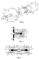
- * à la Figure 2, une vue en coupe longitudinale d'un premier mode de réalisation de l'assemblage de la Figure 1 ;
- * à la Figure 3, une vue en perspective éclatée de l'assemblage d'un profilé de la Figure 1 avec une pièce de fixation murale ;
- * à la Figure 4, une vue en coupe longitudinale de l'assemblage de la Figure 3 et
- * à la Figure 5, une vue en coupe longitudinale d'un second mode de réalisation d'un assemblage des deux profilés tubulaires de la Figure 1.
- * in Figure 1, an exploded perspective view of an assembly of two tubular sections of the same section;
- * in Figure 2, a longitudinal sectional view of a first embodiment of the assembly of Figure 1;
- * in Figure 3, an exploded perspective view of the assembly of a profile of Figure 1 with a wall mounting piece;
- * in Figure 4, a longitudinal sectional view of the assembly of Figure 3 and
- * in FIG. 5, a view in longitudinal section of a second embodiment of an assembly of the two tubular profiles of FIG. 1.
Sur l'ensemble des Figures, les mêmes références désignent les mêmes éléments, quelle que soit la Figure sur laquelle ces derniers apparaissent.Throughout the Figures, the same references designate the same elements, regardless of the Figure on which these appear.
Ainsi, la Figure 1 montre deux profilés tubulaires de section circulaire, désignés respectivement par les références 1 et 2, aptes à être raccordés selon le schéma des Figures 2 ou 5.Thus, FIG. 1 shows two tubular profiles of circular section, designated respectively by the
Pour ce faire, dans chacun des profilés est emmanchée une cheville de configuration cylindrire et oblongue, respectivement 10 et 20, le diamètre desdites chevilles étant très légèrement inférieur à celui de l'ouverture desdits profilés.To do this, in each of the profiles is fitted a pin of cylindrical and oblong configuration, respectively 10 and 20, the diameter of said pins being very slightly less than that of the opening of said profiles.
Lesdites chevilles sont relièes par une tige filetée 3 dont une première extrémité 3a coopére avec la cheville 10, la seconde extrémité 3b coopérant avec la cheville 20. Chaque cheville comporte à cet effet une percée axiale, respectivement 11 et 21, de préférence taraudée, dans laquelle est introduite l'extrémité correspondante de la tige de liaison 3.Said dowels are connected by a threaded
Conformément à l'invention, et comme on peut le voir plus particulièrement sur les Figures 2 et 5, chaque cheville 10 et 20 présente, au voisinage de son extrémité la plus éloignée de l'ouverture de chaque profilé, une chambre, respectivement 12 et 22, de configuration tronconique. La partie de ces chambres présentant la hauteur intérieure la plus importante est munie d'une ouverture communiquant avec les percées axiales 11 et 21 alors que la partie présentant la hauteur intérieure la plus faible est munie d'une ouverture donnant accés à des conduits 13 et 23 opposés auxdites percées axiales et débouchant vers l'intérieur de chaque profilé 1 et 2. Le rôle de ces conduits 13 et 23 sera explicité plus loin.In accordance with the invention, and as can be seen more particularly in FIGS. 2 and 5, each
Dans chaque chambre, 12 et 22, est logé de manière coulissante soit une sphère 5, comme illustré à la Figure 2, soit un élément de forme conique 6, comme montré à la Figure 5.In each chamber, 12 and 22, is slidably housed either a
Dans le premier cas, les sphères 5 sont simplement en contact avec les extrémités 3a et 3b de la tige de liaison 3 alors que dans le second mode de réalisation, les éléments coniques 6 sont solidaires de chaque extrémité de ladite tige.In the first case, the
Dans l'un et l'autre cas, ces éléments sphèriques 5 ou coniques 6, possèdent une section extérieure sensiblement inférieure à la hauteur intérieure la plus importante des chambres 12 et 22 mais supérieure à la hauteur intérieure la plus faible desdites chambres. Ainsi, lorsque ces éléments se déplacent vers les conduits 13 et 23, notamment sous l'effet de la poussée transmise par les extrémités 3a et 3b de la tige de liaison 3, ils provoquent un écartement progressif des parois de cette partie des chambres 12 et 22 de telle sorte que le tronçon des chevilles 10 et 20 où sont situées lesdites chambres, subit une expansion périmétrale. Lesdites chevilles sont alors parfaitement calées contre la paroi interne des profilés qu'elles équipent.In both cases, these spherical 5 or
Afin de faciliter l'expansion du périmètre du tronçon des chevilles contenant les chambres 12 et 22, celui-ci peut être découpé, comme le montre plus particulièrement les Figures 1 et 3, en une pluralité de segments, par exemple quatre segments égaux 100...104 pour la cheville 10 ou 200...204 pour la cheville 20. Ces segments sont délimités par des fentes formées sur une partie de la longueur des chevilles et ouvertes de la surface extérieure de ces dernières à la paroi des chambres 12 et 22.In order to facilitate the expansion of the perimeter of the section of the dowels containing the
Pour réaliser une jonction des profilés avec le dispositif d'assemblage de la Figure 2, il est procédé de la manière suivante : les chevilles 10 et 20, dans les chambres 12 et 22 des-quelles les sphères 5 ont été préalablement introduites, sont tout d'abord engagées dans le profilé qui leur sert de logement respectif, on met en place ensuite la tige de liaison 3 en vissant une de ses extrémités dans la percée axiale de l'une des chevilles, par exemple l'extrémité 3a dans la percée axiale 11 de la cheville 10 qui équipe le profilé 1, on présente alors l'extrémité du second profilé 2 muni de sa cheville 20 et, par un mouvement de rotation dans l'un des sens symbolisés par la flèche à double direction de la Figure 1, par exemple dans le sens dextrorsum, on engage l'extrémité filetée 3b de la tige de liaison 3 dans la percée axiale 21 de la cheville 20 ceci jusqu'à ce que l'extrémité du profilé 2 vienne s'abouter à l'extrémité correspondante du profilé 1. Lors de cette opération d'aboutement des profilés, les extrémités 3a et 3b de la tige de liaison 3 vont pénétrer respectivement dans les chambres 12 et 22 des chevilles 10 et 20 et déplacer les sphères 5 vers les conduits 13 et 23 de manière à provoquer l'écartement des segments 100...104 et 200...204 desdites chevilles.To make a junction of the profiles with the assembly device of FIG. 2, the procedure is as follows: the
Pour désolidariser les deux profilés, il pourra être procédé de la manière inverse, c'est-à-dire en faisant subir une rotation dans le sens senestrorsum au profilé 2. Il suffira alors pour dégager les chevilles, d'expulser éventuellement les sphères 5 vers l'intérieur des profilés par les conduits 13 et 23.To separate the two profiles, it can be done in the opposite way, that is to say by subjecting rotation in the direction senestrorsum to the
Comme on vient de le voir, l'un des principaux avantages offerts par le dispositif d'assemblage de la Figure 2 réside dans sa facilité d'emploi. Il permet notamment de désaccoupler les profilés sans qu'il en résulte nécessairement une destruction des chevilles. En effet, si on souhaite récupérer ces dernières, on dégagera la tige de liaison 3 de manière à permettre aux sphères 5, sous l'effet de l'élasticité des parois des chambres 12 et 22, de revenir à la position illustrée à la Figure 2, au lieu de provoquer leur expulsion par les conduits 13 et 23.As we have just seen, one of the main advantages offered by the assembly device of Figure 2 lies in its ease of use. In particular, it allows the profiles to be uncoupled without necessarily destroying the ankles. Indeed, if one wishes to recover the latter, the connecting
On exécutera les opérations décrites précédemment pour réaliser une jonction avec le dispositif d'assemblage de la Figure 5. Dans ce cas cependant, les éléments coniques 6 étant fixés aux extrémités 3a et 3b de la tige de liaison 3, la mise en place de celle-ci dans les chevilles 10 et 20 sera accompagnée de l'enchâssement des éléments 6 dans leurs chambres respectives 12 et 22.We will execute the operations described above to make a junction with the assembly device of Figure 5. In this case, however, the
Les Figures 3 et 4 montrent l'assemblage du profilé 1 des Figures 1 et 2 avec une pièce qui est constituée par une platine circulaire 4 destinée à être fixée sur un mur au moyen de trois vis introduites dans des perçages 41, 42 et 43.Figures 3 and 4 show the assembly of the
Le profilé 1 est muni de sa cheville 10 qui comporte une percée axiale taraudée 11 communiquant avec une chambre de configuration tronconique 12 dans laquelle est logée une sphère 5.The
Dans l'assemblage illustré, la tige de liaison 3 est constituée par un boulon 3 dont une première extrémité est destinée à être introduite dans la percée axiale 11 après avoir traversé un orifice central 40 de la platine 4, et dont la seconde extrémité est munie classiquement d'une tête 30 qui est immobilisée sur les bords chanfreinés dudit orifice central 40.In the illustrated assembly, the connecting
La fixation du profilé 1 à un mur s'opère de la manière suivante : après mise en place de la cheville 10 dans ledit profilé, on introduit le boulon 3 dans l'orifice 40 de la platine 4 et on solidarise l'ensemble profilé-platine par vissage de telle sorte que la platine 4 vienne en étroit contact avec les bords du profilé. Lors de cette opération, et comme dans l'exemple de la Figure 2, la première extrémité du boulon 3 va pénétrer dans la chambre 12 pour déplacer la sphère 5 vers la partie la plus étroite de cette chambre afin de provoquer une ouverture des segments 100...104 de la portion de cheville enveloppant ladite chambre. On obtient de cette façon un blocage de la cheville dans le profilé, peu susceptible de se relâcher dans le temps.The fixing of the
Il suffit alors d'amener la platine 4 contre un mur et de l'y fixer au moyen de vis introduites dans les perçages 41, 42 et 43.It then suffices to bring the
L'un des intérêts majeurs du dispositif de l'invention est qu'il évite l'emploi de chevilles ou de raccords surdimensionnés pour réaliser des assemblages fiables, comme on aura pu l'observer notamment avec le système proposé par le EP-A-0.423.990. L'existence dans le corps des chevilles d'une chambre, dont le volume peut varier suivant la position d'un élément mobile qui y est inclus, permet en effet de réduire la longueur desdites chevilles dans la mesure où il n'est plus nécessaire de disposer d'une importante surperficie de contact entre la paroi extérieure de ces dernières et la paroi interne des profilés.One of the major advantages of the device of the invention is that it avoids the use of oversized dowels or fittings to produce reliable assemblies, as we have been able to observe in particular with the system proposed by the EP-A- 0.423.990. The existence in the body of the pins of a chamber, the volume of which can vary according to the position of a movable element which is included therein, makes it possible in fact to reduce the length of said pins in so far as it is no longer necessary to have a large contact surface between the outer wall of the latter and the inner wall of the profiles.
Claims (6)
Applications Claiming Priority (2)
| Application Number | Priority Date | Filing Date | Title |
|---|---|---|---|
| FR9207759 | 1992-06-19 | ||
| FR9207759A FR2692631B1 (en) | 1992-06-19 | 1992-06-19 | DEVICE FOR ASSEMBLING A TUBULAR PROFILE WITH A PART OF COMPLEMENTARY STRUCTURE. |
Publications (1)
| Publication Number | Publication Date |
|---|---|
| EP0575255A1 true EP0575255A1 (en) | 1993-12-22 |
Family
ID=9431146
Family Applications (1)
| Application Number | Title | Priority Date | Filing Date |
|---|---|---|---|
| EP93401559A Withdrawn EP0575255A1 (en) | 1992-06-19 | 1993-06-17 | Fastening device of a tubular profile with a part of complementary structure |
Country Status (2)
| Country | Link |
|---|---|
| EP (1) | EP0575255A1 (en) |
| FR (1) | FR2692631B1 (en) |
Cited By (10)
| Publication number | Priority date | Publication date | Assignee | Title |
|---|---|---|---|---|
| DE19514752A1 (en) * | 1995-04-21 | 1996-10-24 | Joachim Kuhn | Device for connecting two cylindrical pipe sections |
| EP0852922A1 (en) * | 1997-01-08 | 1998-07-15 | MHZ HACHTEL GmbH & Co. KG | Connection device |
| EP0852923A1 (en) * | 1997-01-08 | 1998-07-15 | MHZ HACHTEL GmbH & Co. KG | Fastening device for curtain rod |
| AT405088B (en) * | 1997-09-04 | 1999-05-25 | Roehl Hans Heinrich Ing | Plug-in coupling for the connection of shaped pipes |
| WO2005028881A1 (en) * | 2003-09-01 | 2005-03-31 | Dorma Gmbh + Co. Kg | Connection of the face of a pipe to an understructure |
| EP2088891A1 (en) * | 2006-12-05 | 2009-08-19 | Dae Up Sohn | Connector for stick |
| CN107131187A (en) * | 2017-06-26 | 2017-09-05 | 河北工业大学 | A kind of pipe connecting device |
| CN107683375A (en) * | 2015-06-08 | 2018-02-09 | 汽车责任有限公司 | Attachment means between the part of furniture |
| CN111379774A (en) * | 2018-12-31 | 2020-07-07 | 佛山市南海区昭创金属制品有限公司 | Plastic expansion type locking connecting piece |
| CN111577729A (en) * | 2019-02-15 | 2020-08-25 | 佛山市南海区昭创金属制品有限公司 | Fastening piece |
Families Citing this family (1)
| Publication number | Priority date | Publication date | Assignee | Title |
|---|---|---|---|---|
| DE19753545C2 (en) * | 1997-12-03 | 2002-06-13 | Deutsch Zentr Luft & Raumfahrt | Truss structure |
Citations (4)
| Publication number | Priority date | Publication date | Assignee | Title |
|---|---|---|---|---|
| FR356432A (en) * | 1905-07-26 | 1905-11-29 | Daniel Ripamonti | System of wooden dowels for the screwdriving of railway sleepers and tools for the installation of these dowels |
| FR1461206A (en) * | 1965-12-21 | 1966-12-10 | Aime Ledin Ets | Assembly device for tubes and corresponding elements |
| US3437362A (en) * | 1965-03-20 | 1969-04-08 | Adrian Gottfried Offenbroich | Expanding devices |
| DE9104186U1 (en) * | 1991-04-06 | 1991-07-04 | Glauner, Juergen, 7530 Pforzheim, De |
-
1992
- 1992-06-19 FR FR9207759A patent/FR2692631B1/en not_active Expired - Fee Related
-
1993
- 1993-06-17 EP EP93401559A patent/EP0575255A1/en not_active Withdrawn
Patent Citations (4)
| Publication number | Priority date | Publication date | Assignee | Title |
|---|---|---|---|---|
| FR356432A (en) * | 1905-07-26 | 1905-11-29 | Daniel Ripamonti | System of wooden dowels for the screwdriving of railway sleepers and tools for the installation of these dowels |
| US3437362A (en) * | 1965-03-20 | 1969-04-08 | Adrian Gottfried Offenbroich | Expanding devices |
| FR1461206A (en) * | 1965-12-21 | 1966-12-10 | Aime Ledin Ets | Assembly device for tubes and corresponding elements |
| DE9104186U1 (en) * | 1991-04-06 | 1991-07-04 | Glauner, Juergen, 7530 Pforzheim, De |
Cited By (12)
| Publication number | Priority date | Publication date | Assignee | Title |
|---|---|---|---|---|
| DE19514752A1 (en) * | 1995-04-21 | 1996-10-24 | Joachim Kuhn | Device for connecting two cylindrical pipe sections |
| EP0852922A1 (en) * | 1997-01-08 | 1998-07-15 | MHZ HACHTEL GmbH & Co. KG | Connection device |
| EP0852923A1 (en) * | 1997-01-08 | 1998-07-15 | MHZ HACHTEL GmbH & Co. KG | Fastening device for curtain rod |
| AT405088B (en) * | 1997-09-04 | 1999-05-25 | Roehl Hans Heinrich Ing | Plug-in coupling for the connection of shaped pipes |
| WO2005028881A1 (en) * | 2003-09-01 | 2005-03-31 | Dorma Gmbh + Co. Kg | Connection of the face of a pipe to an understructure |
| EP2088891A1 (en) * | 2006-12-05 | 2009-08-19 | Dae Up Sohn | Connector for stick |
| JP2010511849A (en) * | 2006-12-05 | 2010-04-15 | アプ ソーン、ダエ | Pole coupler |
| EP2088891A4 (en) * | 2006-12-05 | 2011-02-16 | Dae Up Sohn | Connector for stick |
| CN107683375A (en) * | 2015-06-08 | 2018-02-09 | 汽车责任有限公司 | Attachment means between the part of furniture |
| CN107131187A (en) * | 2017-06-26 | 2017-09-05 | 河北工业大学 | A kind of pipe connecting device |
| CN111379774A (en) * | 2018-12-31 | 2020-07-07 | 佛山市南海区昭创金属制品有限公司 | Plastic expansion type locking connecting piece |
| CN111577729A (en) * | 2019-02-15 | 2020-08-25 | 佛山市南海区昭创金属制品有限公司 | Fastening piece |
Also Published As
| Publication number | Publication date |
|---|---|
| FR2692631A1 (en) | 1993-12-24 |
| FR2692631B1 (en) | 1995-12-22 |
Similar Documents
| Publication | Publication Date | Title |
|---|---|---|
| EP0575255A1 (en) | Fastening device of a tubular profile with a part of complementary structure | |
| EP0342119A1 (en) | Connecting device for dismountable or modular elements | |
| FR2570160A1 (en) | DEVICE FOR CONNECTING PIPES, PREVENTING A SEPARATION OF THESE PIPELINES | |
| FR2788832A1 (en) | Rapid connector for joining pipe to connector, e.g. for fluid circuits of cars with anti-locking brake systems, has elastic sleeve interacting with shoulder on pipe | |
| FR2468022A1 (en) | Detachable connector for straight or curved tubes - comprises part cylindrical components thrust apart against inside faces of tube walls | |
| EP0009434B1 (en) | Fastening device for convergent tubular members | |
| FR2499417A1 (en) | CONTROL MECHANISM FOR FIRE POST | |
| FR2683017A1 (en) | Coupling for tubes | |
| FR2681918A1 (en) | DEVICE FOR THE QUICK ASSEMBLY AND DISASSEMBLY OF TWO PARTS ON THE OTHER. | |
| FR2463633A1 (en) | PIN-SHAPED ASSEMBLY MEMBER | |
| EP0833093A1 (en) | Device for sealingly butt-coupling two metal pipes | |
| FR2542844A1 (en) | Sanitary hose nipple connector | |
| WO1989000634A1 (en) | Punctual fixing device for elements presenting an edge, particularly plates on a supporting structure | |
| FR2618862A1 (en) | Device for assembling tubes or the like comprising a hollow housing in the form of a cylinder or the like | |
| FR2594206A1 (en) | PHONIC DAMPING DEVICE FOR SANITARY FACILITY DRIVING | |
| EP1108821B1 (en) | Sanitary assembly comprising a cistern and a toilet bowl | |
| EP0014123A2 (en) | Process and apparatus for joining fluid flow ducts | |
| WO2002021033A2 (en) | Single-piece compression ring (consisting of several elements (zone) in one single piece) mainly for joint compression pipe connections designed for industrial applications (railways) | |
| EP0791756A1 (en) | Dowell anchor for solid and hollow materials | |
| FR2634525A1 (en) | Device for assembling sections | |
| EP1092880A1 (en) | Screw-type fastening means allowing adjustment between two elements | |
| FR2687194A1 (en) | System for assembling sections | |
| FR2795462A1 (en) | Unit for the solidification and the blocking in a recess for the fixing in position of objects | |
| EP0741251A1 (en) | Fastening element for the mounting on a threaded bolt | |
| FR2513736A1 (en) | Temporary display stand assembly - uses hollow spherical nodes with perforations for joining structural rods |
Legal Events
| Date | Code | Title | Description |
|---|---|---|---|
| PUAI | Public reference made under article 153(3) epc to a published international application that has entered the european phase |
Free format text: ORIGINAL CODE: 0009012 |
|
| AK | Designated contracting states |
Kind code of ref document: A1 Designated state(s): DE ES GB IT |
|
| STAA | Information on the status of an ep patent application or granted ep patent |
Free format text: STATUS: THE APPLICATION IS DEEMED TO BE WITHDRAWN |
|
| 18D | Application deemed to be withdrawn |
Effective date: 19940623 |