EP0575151A1 - Vehicular left/right drive force adjusting apparatus - Google Patents
Vehicular left/right drive force adjusting apparatus Download PDFInfo
- Publication number
- EP0575151A1 EP0575151A1 EP93304658A EP93304658A EP0575151A1 EP 0575151 A1 EP0575151 A1 EP 0575151A1 EP 93304658 A EP93304658 A EP 93304658A EP 93304658 A EP93304658 A EP 93304658A EP 0575151 A1 EP0575151 A1 EP 0575151A1
- Authority
- EP
- European Patent Office
- Prior art keywords
- axle
- speed increasing
- differential
- decreasing
- speed
- Prior art date
- Legal status (The legal status is an assumption and is not a legal conclusion. Google has not performed a legal analysis and makes no representation as to the accuracy of the status listed.)
- Granted
Links
Images


Classifications
-
- B—PERFORMING OPERATIONS; TRANSPORTING
- B60—VEHICLES IN GENERAL
- B60K—ARRANGEMENT OR MOUNTING OF PROPULSION UNITS OR OF TRANSMISSIONS IN VEHICLES; ARRANGEMENT OR MOUNTING OF PLURAL DIVERSE PRIME-MOVERS IN VEHICLES; AUXILIARY DRIVES FOR VEHICLES; INSTRUMENTATION OR DASHBOARDS FOR VEHICLES; ARRANGEMENTS IN CONNECTION WITH COOLING, AIR INTAKE, GAS EXHAUST OR FUEL SUPPLY OF PROPULSION UNITS IN VEHICLES
- B60K17/00—Arrangement or mounting of transmissions in vehicles
- B60K17/04—Arrangement or mounting of transmissions in vehicles characterised by arrangement, location, or kind of gearing
- B60K17/16—Arrangement or mounting of transmissions in vehicles characterised by arrangement, location, or kind of gearing of differential gearing
- B60K17/20—Arrangement or mounting of transmissions in vehicles characterised by arrangement, location, or kind of gearing of differential gearing in which the differential movement is limited
-
- B—PERFORMING OPERATIONS; TRANSPORTING
- B60—VEHICLES IN GENERAL
- B60K—ARRANGEMENT OR MOUNTING OF PROPULSION UNITS OR OF TRANSMISSIONS IN VEHICLES; ARRANGEMENT OR MOUNTING OF PLURAL DIVERSE PRIME-MOVERS IN VEHICLES; AUXILIARY DRIVES FOR VEHICLES; INSTRUMENTATION OR DASHBOARDS FOR VEHICLES; ARRANGEMENTS IN CONNECTION WITH COOLING, AIR INTAKE, GAS EXHAUST OR FUEL SUPPLY OF PROPULSION UNITS IN VEHICLES
- B60K23/00—Arrangement or mounting of control devices for vehicle transmissions, or parts thereof, not otherwise provided for
- B60K23/04—Arrangement or mounting of control devices for vehicle transmissions, or parts thereof, not otherwise provided for for differential gearing
-
- F—MECHANICAL ENGINEERING; LIGHTING; HEATING; WEAPONS; BLASTING
- F16—ENGINEERING ELEMENTS AND UNITS; GENERAL MEASURES FOR PRODUCING AND MAINTAINING EFFECTIVE FUNCTIONING OF MACHINES OR INSTALLATIONS; THERMAL INSULATION IN GENERAL
- F16H—GEARING
- F16H48/00—Differential gearings
- F16H48/06—Differential gearings with gears having orbital motion
- F16H48/10—Differential gearings with gears having orbital motion with orbital spur gears
-
- Y—GENERAL TAGGING OF NEW TECHNOLOGICAL DEVELOPMENTS; GENERAL TAGGING OF CROSS-SECTIONAL TECHNOLOGIES SPANNING OVER SEVERAL SECTIONS OF THE IPC; TECHNICAL SUBJECTS COVERED BY FORMER USPC CROSS-REFERENCE ART COLLECTIONS [XRACs] AND DIGESTS
- Y10—TECHNICAL SUBJECTS COVERED BY FORMER USPC
- Y10T—TECHNICAL SUBJECTS COVERED BY FORMER US CLASSIFICATION
- Y10T74/00—Machine element or mechanism
- Y10T74/21—Elements
- Y10T74/2186—Gear casings
Abstract
Description
- This invention relates to a vehicular left/right drive torque adjusting apparatus suitable for use in the distribution of drive torque to the left and right wheels in a four-wheel-drive or two-wheel-drive automotive vehicle.
- Recent years have seen major developments in four-wheel-drive (hereinafter called "4WD") automotive vehicles, including a variety for full-time 4WD automotive vehicles where improvements include positive adjustment of the division of torque (drive torque) between front and rear wheels.
- When two members which are rotating at different rotational speeds are coupled together, the difference in their rotational speeds is generally reduced and torque is usually transferred from the side of the member rotating at the higher speed to the side of the member rotating at the lower speed. Differential-limiting, front/rear torque distribution apparatuses making use of these characteristics have been proposed.
- Distribution of torque between the front and rear wheels can be adjusted, for example, by providing a center differential, which is arranged between the front wheels and the rear wheels, with a differential limiting mechanism of the frictional engagement type to limit differential motion (a difference in rotational speed) between the front and rear wheels and controlling the state of engagement of the differential limiting mechanism. As the differential limiting mechanism, a hydraulic multi-plate clutch, use of an electromagnetic clutch or the like can be considered. When a hydraulic multi-plate clutch is used, the state of engagement of the hydraulic multi-plate clutch, that is, of the differential limiting mechanism can be controlled by adjusting the position of a hydraulic pressure control valve in accordance with a computer or the like.
- Taking in a broad sense a mechanism for distributing torque to left and right wheels in an automotive vehicle, on the other hand, it is considered to include conventional normal differentials as well as LSDs (limited slip differentials) including those of the electronic control type. They however do not positively adjust the distribution of torque, so that they cannot distribute torque between left and right wheels as desired.
- Therefore it is also desired to develop an apparatus capable of adjusting the distribution of torque between the left and right wheels in addition to an apparatus for permitting adjustment of the distribution of torque between the front and rear wheels. In this case, the left/right torque distribution adjusting apparatus is intended for use in the adjustment of torque distribution not only between the left and right driving wheels in a 4WD vehicle but also between the left and right driving wheels in a 2WD vehicle such as a front wheel drive vehicle or a rear wheel drive vehicle.
- Incidentally, it is desired for a torque distribution mechanism that the distribution of torque can be effected as desired without inducing any large torque loss or energy loss. It is also desired to reduce the size and weight of the mechanism as much as possible.
- An object of this invention is to provide an improved vehicular left/right drive torque adjusting apparatus.
- Specific improvements may be (i) to permit the distribution of torque between left and right wheels without inducing any substantial torque loss or energy loss, (ii) to reduce the size and weight of the apparatus, (iii) to improve the responsibility to control, (iv) to facilitate the maintenance of the apparatus, and (v) to permit easy assembly without failure.
- According to the present invention there is provided a vehicular left/right drive torque adjusting apparatus having, between a left-wheel axle and a right-wheel axle in a vehicle, input means for receiving drive torque from an engine, a differential mechanism for transmitting drive torque, which has been inputted from said input means, to the left-wheel axle and the right-wheel axle while permitting differential motion between the left-wheel axle and the right-wheel axle, and a drive torque transmission control mechanism for controlling the state of transmission of the drive torque to permit adjustment of the distribution of the drive torque to the left and right wheels characterised in that the drive torque transmission control mechanism comprises:
a speed increasing/decreasing mechanism interposed between the left-wheel axle and the right-wheel axle and constructed integrally of a speed increasing mechanism and a speed decreasing mechanism, said speed increasing mechanism being adapted to increase a rotational speed of one of the axles and then to output the thus-increased rotational speed to a first intermediate axle, and said speed decreasing mechanism being adapted to decrease a rotational speed of said one axle and then to output the thus-decreased rotational speed to a second intermediate axle;
a first coupling of the variable transmitted torque capacity type interposed between the first intermediate axle and the other axle and adapted to transmit drive torque between the first intermediate axle and the other axle; and
a second coupling of the variable transmitted torque capacity type interposed between the second intermediate axle and the other axle and adapted to transmit drive torque between the second intermediate axle and the other axle. - In a preferred embodiment, the first and second couplings of the variable transmitted torque capacity type are adjacent to each other and are integrally constructed as an integral coupling. The differential mechanism, the speed increasing/decreasing mechanism and the integral couplings can be arranged coaxially.
- In the preferred embodiment, the first and second couplings of the variable transmitted torque capacity type can be constructed as electrically-controlled, hydraulic multi-plate clutches, respectively. The electrically-controlled, hydraulic multi-plate clutches can desirably be integrated in series to form the integral coupling.
- In the preferred embodiment, the integral coupling can be disposed with a partition interposed between the integral coupling and the differential mechanism and speed increasing/decreasing mechanism.
- In the preferred embodiment, the differential mechanism can be constructed preferably of a planetary differential mechanism. The planetary differential mechanism can comprise a ring gear, a planetary carrier and a sun gear, the ring gear is connected to said input means so that the ring gear can integrally rotate with said input means, the planetary carrier can be connected to one of the axles so that the planetary carrier can integrally rotate with the one axle, the sun gear can be connected to the other axle so that the sun gear can integrally rotate with the other axle, the one axle and the other axle can be coaxially arranged on left and right sides of the planetary differential mechanism, respectively, the speed increasing/ decreasing mechanism can be arranged on the side of the other axle, and the integral coupling can be arranged outside the speed increasing/decreasing mechanism on the side of the other axle. If desired, a third intermediate axle may be interposed between the one axle and the speed increasing/decreasing mechanism to connect the one axle and the speed increasing/decreasing mechanism to each other via the third intermediate axle, the speed increasing mechanism of the speed increasing/decreasing mechanism may be constructed of a gear mechanism interposed between the third intermediate axle and the first intermediate axle, and the speed decreasing mechanism of the speed increasing/decreasing mechanism may be constructed of a gear mechanism interposed between the third intermediate axle and the second intermediate axle.
- In the apparatus according to this invention the speed increasing/decreasing mechanism can be constructed of a compound planetary gear mechanism in which an input sun gear integrally rotatable with a third axle, a first output sun gear integrally rotatable with the first intermediate axle, a second output sun gear integrally rotatable with the second intermediate axle, an input planetary gear rotatable in mesh with the input sun gear, and a first output planetary gear rotatable in mesh with the first output sun gear and a second output planetary gear rotatable in mesh with the second output sun gear are integrally connected together. Preferably, the first and second couplings of the variable transmitted torque capacity type can be adjacent to each other and can be integrally constructed as an integral coupling, and the differential mechanism, the speed increasing/decreasing mechanism and the integral couplings can be arranged coaxially.
- In the apparatus according to this invention, the differential mechanism and the speed increasing/decreasing mechanism can be accommodated within a differential carrier so that the differential mechanism and the speed increasing/decreasing mechanism are isolated from each other by a partition.
- In the apparatus according to this invention, the input means and the speed increasing/decreasing mechanism can desirably be arranged substantially along an imaginary base line which extends in a front-to-rear direction of the vehicle, and the differential mechanism can be arranged on one side of the imaginary base line, and the first and second couplings of the variable transmitted torque capacity type can be arranged on the opposite side of the imaginary base line.
- An embodiment of the invention will now be described, by way of example only, with reference to the accompany-drawings of which:
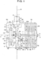
- FIG. 1 is a schematic skeleton diagram showing a vehicular left/right drive torque adjusting apparatus according to one embodiment of the present invention;
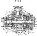
- FIG. 2 is a substantially horizontal, cross-sectional view specifically illustrating the construction of the vehicular left/right drive torque adjusting apparatus according to one embodiment of the present invention;
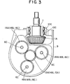
- FIG. 3 is a substantially vertical, cross-sectional view showing the layout of a speed increasing/decreasing mechanism in the vehicular left/right drive torque adjusting apparatus according to one embodiment of the present invention;
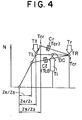
- FIG. 4 is a speed diagram depicting a relationship in speed among certain essential elements in the vehicular left/right drive torque adjusting apparatus according to one embodiment of the present invention during straight running;
- FIG. 5 is a speed diagram showing a relationship in speed among the essential elements in the vehicular left/right drive torque adjusting apparatus according to one embodiment of the present invention during rightward turning;
- FIG. 6 is a speed diagram showing a relationship in speed among the essential elements in the vehicular left/right drive torque adjusting apparatus according to one embodiment of the present invention during leftward turning; and
- FIG. 7 is a simplified block diagram illustrating a drive torque transmission system in a vehicle equipped with the vehicular left/right drive torque adjusting apparatus according to one embodiment of the present invention.
- The vehicular left/right drive torque adjusting apparatus according to one embodiment of the present invention is installed at the part of a rear differential of an automotive vehicle to perform left-to-right or right-to-left transfer of drive torque between rear wheels. In the illustrated embodiment, especially, the apparatus is disposed on a side of the rear wheels of a 4WD vehicle. drive torque outputted to the side of the rear wheels via a center differential is received by an input shaft via a drive shaft, whereby the drive torque can be distributed rightwards and leftwards.
- A description will first be made of the overall construction of the drive system of the vehicle equipped with the apparatus. As is illustrated in FIG. 7, drive torque from an
engine 21 is received by acenter differential 23, which is constructed of planetary gears, via atransmission 22. The drive torque is then transmitted from thecenter differential 23 to a front wheel side and also to a rear wheel side. - The
center differential 23 is provided with a known differential limitingdevice 25 which can suitably limit differential motion betweenfront wheels rear wheels device 25 is constructed of a hydraulic multi-plate clutch and is designed to be able to control the distribution of drive torque to the front and rear wheels while limiting differential motion between the front and rear wheels in accordance with hydraulic pressure supplied, so that the differential limitingdevice 25 serves as a device for controlling the distribution of drive torque between the front and rear wheels. - One of amounts of drive torque divided by the
center differential 23 as described above is transmitted to the left and rightfront wheels front differential 24. On the other hand, the other amount of drive torque distributed from thecenter differential 23 is transmitted to a reardifferential unit 28 via adrive shaft 26 and is then transmitted to the left and rightrear wheels differential unit 28. - Constructed in the rear
differential unit 28 is the vehicular left/right drive torque adjusting apparatus according to one embodiment of the present invention, as designated atnumeral 20. As is shown in detail in FIGS. 1 and 2, the vehicular left/right drivetorque adjusting apparatus 20 is constructed of arear differential 4 and a drive torquetransmission control mechanism 5 disposed in the proximity of therear differential 4. The drive torquetransmission control mechanism 5 is in turn constructed of a speed increasing/decreasing mechanism 6 and first andsecond couplings - The first and
second couplings multi-plate clutch mechanism 25 of the above-described front/rear drive torque adjusting apparatus, by acontrol unit 27 as control means. - Namely, the hydraulic system for the first and
second couplings multi-plate clutch mechanism 25 are composed of unillustrated hydraulic pressure compartments formed in association with the corresponding clutch mechanisms, a motor-operatedpump 29A and anaccumulator 29B, said pump and accumulator making up a hydraulic pressure source, and a clutch hydraulicpressure control valve 29C for feeding a hydraulic pressure of the hydraulic pressure source to the hydraulic pressure compartments in an amount as needed. - As is generally practiced in control of this type, the
control unit 27 controls the opening or position of the clutch hydraulicpressure control valve 29C, for example, on the basis of information from various sensors such aswheel speed sensor - The vehicular left/right drive
torque adjusting apparatus 20 will now be described in detail. - As is illustrated in FIGS. 1 and 2, the apparatus is disposed to couple an input shaft (input means) 1, which is adapted to receive rotational drive torque distributed to the rear wheel side out of an engine output of the automotive vehicle, with left-wheel output shaft (a left-wheel axle) 2 and right-wheel output shaft (a right-wheel axle) 3, said
axles transmission control mechanism 5. Incidentally, the left-wheel axle 2 is connected at a left end thereof to a drive system for the left wheel and the right-wheel axle 3 is connected at a right end thereof to a drive system for the right wheel. - It is the drive torque
transmission control mechanism 5 that serves as the center in the apparatus. Themechanism 5 is constructed, as described above, of the speed increasing/decreasing mechanism 6, thefirst coupling 7 of the variable transmitted torque capacity type, and thesecond coupling 8 of the variable transmitted torque capacity type. - The
differential mechanism 4, the speed increasing/decreasing mechanism 6 and thecouplings decreasing mechanism 6 are disposed substantially along animaginary base line 19 which extends in a front-to-rear direction of the vehicle. With respect to thebase line 19, thedifferential mechanism 4 is arranged on the left side while the first andsecond couplings base line 19 is indicated as such a phantom that extends substantially along an axis of thedrive shaft 26. The positional relationship between thedifferential mechanism 4 and the first andsecond couplings differential mechanism 4 on the right side and the first andsecond couplings base line 19. - Although the electronically-controlled, hydraulic multi-plate
clutch mechanisms - In the case of friction clutches, those permitting adjustment of coupling force by hydraulic pressure or the like as in multi-plate clutches appear to be preferred. With such friction clutches, in particular, it seems to be desirous to arrange friction clutches, each of which can transmit torque in one direction, in desired directions (for example, in their torque-transmitting directions), respectively.
- As VCUs or HCUs, those having adjustable power transmission characteristics are suited although conventional ones having fixed power transmission characteristics may also be used. For the adjustment of such coupling force or power transmission characteristics, it seems to be possible to use, besides hydraulic pressure, other drive torque such as electromagnetic force.
- The
couplings couplings 7,8'' for the sake of brevity. - The above elements will hereinafter be described individually in order.
- The input shaft 1 is rotatably supported on a
differential carrier 9 with abearing 10 interposed therebetween. A hypoid pinion 1A is mounted on one end of the input shaft 1. The pinion 1A is rotatable in mesh with acrown gear 12 fixed on a differential case 11 so that rotation of the pinion 1A is transmitted to the differential case 11. - Arranged inside the differential case 11 is a
rear differential 4 of the planetary gear type. Therear differential 4 of the planetary gear type is of the double pinion type, and is constructed of aring gear 4A formed on an inner wall of the differential case 11, aplanetary carrier 4B integrally rotatable with the left-wheel axle 2,planetary pinions planetary shaft 4E of theplanetary carrier 4B, and asun gear 4D integrally rotatable with the right-wheel axle 3. Incidentally, theplanetary pinions - As a consequence, rotation of the differential case 11 drives the
planetary pinions ring gear 4A which integrally rotates with the differential case 11. Theplanetary pinions sun gear 4D while self-rotating about theplanetary shaft 4E. Depending on the revolution, rotational force is transmitted to the left-wheel axle 2 via theplanetary carrier 4B. Depending on balancing between the revolution and self-rotation, rotational force is transmitted to the right-wheel axle 3 via thesun gear 4D. Theplanetary pinions - Next to the
rear differential 4, the speed increasing/decreasingmechanism 6 of the drive torquetransmission control mechanism 5 is disposed. - This speed increasing/decreasing
mechanism 6 is interposed between a hollow intermediate axle (third intermediate axle) 13, which is connected to thecarrier 4B so that thethird axle 13 can rotate integrally with the left-wheel axle 2 via thecarrier 4B, and another hollow intermediate axle (first intermediate axle) 14 and a further hollow intermediate axle (second intermediate axle) 15, said first and secondintermediate axles second couplings - These
intermediate axles intermediate axles wheel axle 3 so that they can rotate relative to the right-wheel axle 3. Theintermediate axle 15, on the other hand, is arranged on an outer peripheral wall of theintermediate axle 14 so that theintermediate axle 15 can rotate relative to theintermediate axle 14. - Namely, the
intermediate axle 13 is rotatably supported between the right-wheel axle 3 and apartition 16, theintermediate axle 14 between the right-wheel axle 3 and theintermediate axle 15, and theintermediate axle 15 on the outer peripheral wall of theintermediate axle 14. As is illustrated in FIG. 1, thepartition 16 and anotherpartition 17, the latter partition being to be described subsequently herein, divide the interior of thedifferential carrier 9 into threespaces rear differential 4 is accommodated in thespace 9A, the speed increasing/ decreasingmechanism 6 in the space 9B, and the first andsecond couplings space 9C. - These
intermediate axles - Between the
intermediate axle 13 and thepartition 16 as well as theintermediate axle 13 and the right-wheel axle 3, oil seals 10D are interposed respectively, so that the side of therear differential 4 and the side of the speed increasing/decreasingmechanism 6 and thecouplings - The speed increasing/decreasing
mechanism 6 is constructed of aspeed increasing mechanism 6A and aspeed decreasing mechanism 6B. Thesespeed increasing mechanism 6A andspeed decreasing mechanisms 6B are formed of the compound planetary gear mechanism. - Namely, as illustrated in FIG. 3, plural (three in the illustrated embodiment) fixed
planetary shafts 6C are disposed around the right-wheel axle 3 in a phase shifted from the hypoid pinion 1A. On each of theseplanetary shafts 6C, a compoundplanetary pinion 6D provided with three kinds ofgears - To be rotatable in mesh with the individual gears 18A,18B,18C of the compound
planetary pinion 6D, there are mounted a gear (sun gear) 13A on theintermediate axle 13, another gear (sun gear) 14A on theintermediate axle 14 and a further gear (sun gear) 15A on theintermediate axle 15, respectively. - These
gears gears gears gears - The
speed increasing mechanism 6A is constructed of the combination of thegears speed decreasing mechanism 6B is constructed of the combination of thegears - When rotation of the
intermediate axle 13 is transmitted to theintermediate axle 14 along a path which extends through thegears speed increasing mechanism 6A, theintermediate axle 14 rotates at a higher speed than theintermediate axle 13 because of the ratio of the number of teeth of the respective gears. When rotation of theintermediate axle 13 is transmitted to theintermediate axle 15 along a path which extends through thegears speed decreasing mechanism 6B, on the other hand, theintermediate axle 15 rotates at a lower speed than theintermediate axle 13 because of the ratio of the number of teeth of the respective gears. - An output of the speed increasing/decreasing
mechanism 6 of such a construction as described above is inputted to the side of thecoupling intermediate axle - The
intermediate axles planetary shaft 6C,planetary pinion 6D and sun gears 13A,14A,15A. - The first and
second couplings space 9C of thedifferential carrier 9 as described above. It is to be noted that thesecouplings mechanism 6. This arrangement facilitates a dimensional reduction and oil control of the apparatus. - The
respective couplings clutch plates wheel axle 3,clutch plates intermediate axles hydraulic pistons clutch plates hydraulic pistons drain systems clutch plates - When the
coupling 7 is caused to engage by control through the controller, drive torque is transferred from the side of theintermediate axle 14 rotating at a high speed during usual running other than prompt turning, to the right-wheel axle 3, namely, from the side of the left-wheel axle 2 to the side of the right-wheel axle 3. As a result, the drive torque for the right-wheel becomes greater than that for the left-wheel. - When the
coupling 8 is conversely caused to engage by control through the controller, drive torque is transferred from the side of the right-wheel axle 3 to the side of theintermediate axle 15 rotating at a lower speed than the right-wheel axle 3, that is, from the side of the right-wheel axle 3 to the side of the left-wheel axle 2 during normal running other than quick turning. As a consequence, the drive torque for the left wheel becomes greater than that for the right wheel. - As is evident from the foregoing, the apparatus of this embodiment makes use of the principle that torque is transmitted from a faster side to a slower side in a slip clutch or the like.
- FIGS. 1 and 2 also show needle bearings 10B,
roller bearings 10C, and the oil seals 10D. - Since the vehicular left-right drive torque adjusting apparatus according to the one embodiment of this invention is constructed as described above, actuation of the
couplings - Moreover, the distribution of torque is adjusted by transferring a desired amount of torque of one of the left and right wheels to the other wheel instead of adjusting the torque distribution by using an energy loss such as braking. It is therefore possible to achieve distribution of torque at a desired ratio without inducing any substantial torque loss or energy loss.
- In the apparatus of the present embodiment, the
couplings - Further, a change-over switch for the direction of control has been omitted so that drive torque is transmitted directly to each of the
couplings mechanism 6. This has led to substantial improvements in control responsibility. - The
rear differential 4 is constructed of the planetary differential of the double pinion type, and the speed increasing/decreasingmechanism 6 constructed of the integral unit of thespeed increasing mechanism 6A and thespeed decreasing mechanism 6B is disposed. It is hence possible to arrange all the mechanisms on a common axis. - The input shaft 1 and the speed increasing/decreasing
mechanism 6 are arranged substantially along thebase line 19, and thedifferential mechanism 4 and the first andsecond couplings partition 16 and thepartition 17. As a result, the gears and the multi-plate clutch, which use different oils, can be separated, leading to the advantages that the apparatus can be constructed compact and the control of the oils can be facilitated. - The compound planetary gear mechanism is used as the speed increasing/decreasing
mechanism 6. Owing to the self-centering effect of the gears, the axes of theintermediate axles mechanism 6 can therefore be operated stably. - The parallel dual-axes type which makes use of a countershaft requires bearings having sufficient stiffness. Such bearings are no longer required for the compound planetary gear mechanism, thereby making it possible to proceed with a further dimensional reduction in mechanism.
- It is however to be noted that the use of such a compound planetary gear mechanism as the speed increasing/decreasing
mechanism 6 is not absolutely essential. The speed increasing/decreasingmechanism 6 can, for example, be of the above-mentioned parallel dual-axes type which makes use of a countershaft. - In the apparatus of the present embodiment, a relationship in speed among a rotational speed on the side of the input means, an output on the side of the right wheel and an output on the side of the left wheel can be illustrated as shown in FIGS. 4 to 6. FIG. 4 shows respective speeds when both the
couplings - In the individual diagrams, Ti represents input torque to the
differential case 10, Tℓ and Tr torques distributed to the right and left wheels, respectively, Tcr torque transmitted rightwards when the coupling on the side of the right wheel is caused to engage, and Tcℓ torque transmitted leftward when the coupling on the side of the left wheel is caused to engage. There are also shown a rotational speed DC of thedifferential case 10, a rotational speed TR on the side of the right wheel, and a rotational speed TL on the side of the left wheel. - A discussion will next be made on the setting of the planetary gear in the vehicular left/right drive torque adjusting apparatus, a relational formula of torque distribution, an energy loss and a torque loss.
(1) Setting of the planetary gear: - A left-to-right differential shift ratio S can be expressed by the following formula:

where - VDC:
- rotational speed of the
differential case 10
(= Vin: rotational speed of an input shaft). - Vr:
- rotational speed of the right-
wheel axle 3. - Assuming that the left-to-right differential shift ratio during critical turning (turning in which the speed increasing or decreasing function of the speed increasing/decreasing
mechanism 6 is maintained) is Smax (hereinafter abbreviated as "Sm"),
From the above formulae (1·1) and (1·2),
If Z₁ = Z₄, the formula (1.3) can be simplified to:
- Setting of the planetary gear can be conducted as described above.
(2) The relational formula of torque distribution is next derived. - In the following discussion, Ti represents input torque to the
differential case 10, Tℓ and Tr torques distributed to the right and left wheels, respectively, Tcr torque transmitted rightwards when the coupling on the side of the right wheel is caused to engage, and Tcℓ torque transmitted leftward when the coupling on the side of the left wheel is caused to engage. - (i) Upon engagement of the right-side coupling R (which is designated by
numeral 7 in the embodiment); From the formula of equilibrium of the differential gear,


- (ii) Upon engagement of the left-side coupling L (which is designated by
numeral 8 in the embodiment): From the formula of equilibrium of the differential gear, - Distribution of torque can be calculated in the manner as described above.
(3) Energy loss (i.e., energy momentarily absorbed in the clutch) per unit time, ΔE, will next be determined. - Energy loss will be discussed under conditions that make the left-to-right differential shift ratio S satisfy the following inequality:

- In the following discussion, the slip speed ratio of the coupling R will be represented by Scr while that of the coupling L will be designated by Scℓ.
- (i) With respect to the right-side coupling R (which is designated by
numeral 7 in the embodiment),


- ωDC:
- rotational speed of differential case
(rad/s).
- (ii) With respect to the left-hand coupling L (which is designated by
numeral 8 in the embodiment),


- (i) Upon engagement of the right-side coupling R (which is designated by
numeral 7 in the embodiment):
- (ii) Upon engagement of the left-side coupling L (which is designated by
numeral 8 in the embodiment):
Upon setting the apparatus of the embodiment, its characteristics can be studied for example in the manner described above.
From formulae (1.2) and (2.5), the torques of the left and right wheels can be expressed as follows:
The amount (ΔT) of torque to be transferred is
The coupling torque Tcr needed for the transfer of the amount (ΔT) of torque is then given by the following formula:
(4) Torque loss TL (TL: input torque > output torque) will next be determined.
Claims (11)
- A vehicular left/right drive torque adjusting apparatus having, between a left-wheel axle (2) and a right-wheel axle (3) in a vehicle, input means (1) for receiving drive torque from an engine, a differential mechanism (4) for transmitting drive torque, which has been inputted from said input means (1), to the left-wheel axle (2) and the right-wheel axle (3) while permitting differential motion between the left-wheel axle (2) and the right-wheel axle (3), and a drive torque transmission control mechanism (5) for controlling the state of transmission of the drive torque to permit adjustment of the distribution of the drive torque to the left and right wheels, characterized in that the drive torque transmission control mechanism (5) comprises:
a speed increasing/decreasing mechanism (6) interposed between the left-wheel axle (2) and the right-wheel axle (3) and constructed integrally of a speed increasing mechanism (6A) and a speed decreasing mechanism (6B), said speed increasing mechanism (6A) being adapted to increase a rotational speed of one (2) of the axles (2,3) and then to output the thus-increased rotational speed to a first intermediate axle (14), and said speed decreasing mechanism (6B) being adapted to decrease a rotational speed of said one axle (2) and then to output the thus-decreased rotational speed to a second intermediate axle (15);
a first coupling (7) of the variable transmitted torque capacity type interposed between the first intermediate axle (14) and the other axle (3) and adapted to transmit drive torque between the first intermediate axle (14) and the other axle (3); and
a second coupling (8) of the variable transmitted torque capacity type interposed between the second intermediate axle (15) and the other axle (3) and adapted to transmit drive torque between the second intermediate axle (15) and the other axle (3). - An apparatus of claim 1, wherein the first and second couplings (7,8) of the variable transmitted torque capacity type are adjacent to each other and are integrally constructed as an integral coupling; and the differential mechanism (4), the speed increasing/ decreasing mechanism and the integral couplings (7,8) are arranged coaxially.
- An apparatus of claim 2, wherein the first and second couplings (7,8) of the variable transmitted torque capacity type are constructed as electrically-controlled, hydraulic multi-plate clutches, respectively; and the electrically-controlled, hydraulic multi-plate clutches are integrated in series to form the integral coupling (7,8).
- An apparatus of claim 2, wherein the integral coupling (7,8) is disposed with a partition (17) interposed between the integral coupling (7,8) and the differential mechanism (4) and speed increasing/decreasing mechanism (6).
- An apparatus of claim 2, wherein the differential mechanism (4) is constructed of a planetary differential mechanism.
- An apparatus of claim 5, wherein the planetary differential mechanism (4) comprises a ring gear (4A), a planetary carrier (4B) and a sun gear (4D), the ring gear (4A) is connected to said input means (1) so that the ring gear (4A) integrally rotates with said input means (1), the planetary carrier (4B) is connected to one (2) of the axles (2,3) so that the planetary carrier (4B) integrally rotates with the one axle (2), the sun gear (4D) is connected to the other axle (3) so that the sun gear (4D) integrally rotates with the other axle (3), the one axle (2) and the other axle (3) are coaxially arranged on left and right sides of the planetary differential mechanism (4), respectively, the speed increasing/decreasing mechanism (6) is arranged on the side of the other axle (3), and the integral coupling (7,8) is arranged outside the speed increasing/decreasing mechanism (6) on the side of the other axle (3).
- An apparatus of claim 6, wherein a third intermediate axle (13) is interposed between the one axle (2) and the speed increasing/decreasing mechanism (6) to connect the one axle (2) and the speed increasing/ decreasing mechanism (6) to each other via the third intermediate axle (13), the speed increasing mechanism (6A) of the speed increasing/decreasing mechanism (6) is constructed of a gear mechanism (13A,18A,18B,14A) interposed between the third intermediate axle (13) and the first intermediate axle (14), and the speed decreasing mechanism (6B) of the speed increasing/ decreasing mechanism (6) is constructed of a gear mechanism (13A,18A,18C,15A) interposed between the third intermediate axle (13) and the second intermediate axle (15).
- An apparatus of claim 1, wherein the speed increasing/decreasing mechanism (6) is constructed of a compound planetary gear mechanism (6D) in which an input sun gear (13A) integrally rotatable with a third axle (13), a first output sun gear (14A) integrally rotatable with the first intermediate axle (14), a second output sun gear (15A) integrally rotatable with the second intermediate axle (15), an input planetary gear (18A) rotatable in mesh with the input sun gear (13A), and a first output planetary gear (18B) rotatable in mesh with the first output sun gear (14A) and a second output planetary gear (18C) rotatable in mesh with the second output sun gear (15A) are integrally connected together.
- An apparatus of claim 8, wherein the first and second couplings (7,8) of the variable transmitted torque capacity type are adjacent to each other and are integrally constructed as an integral coupling; and the differential mechanism (4), the speed increasing/ decreasing mechanism and the integral couplings (7,8) are arranged coaxially.
- An apparatus of claim 1, wherein the differential mechanism (4) and the speed increasing/ decreasing mechanism (6) are accommodated within a differential carrier (9) so that the differential mechanism (4) and the speed increasing/decreasing mechanism (6) are isolated from each other by a partition (16).
- An apparatus of claim 1, wherein the input means (1) and the speed increasing/decreasing mechanism (6) are arranged substantially along an imaginary base line (19) which extends in a front-to-rear direction of the vehicle; and the differential mechanism (4) is arranged on one side of the imaginary base line (19), and the first and second couplings (7,8) of the variable transmitted torque capacity type are arranged on the opposite side of the imaginary base line (19).
Applications Claiming Priority (2)
| Application Number | Priority Date | Filing Date | Title |
|---|---|---|---|
| JP4155427A JP2738225B2 (en) | 1992-06-15 | 1992-06-15 | Left and right driving force adjustment device for vehicles |
| JP155427/92 | 1992-06-15 |
Publications (2)
| Publication Number | Publication Date |
|---|---|
| EP0575151A1 true EP0575151A1 (en) | 1993-12-22 |
| EP0575151B1 EP0575151B1 (en) | 1996-01-31 |
Family
ID=15605779
Family Applications (1)
| Application Number | Title | Priority Date | Filing Date |
|---|---|---|---|
| EP93304658A Expired - Lifetime EP0575151B1 (en) | 1992-06-15 | 1993-06-15 | Vehicular left/right drive force adjusting apparatus |
Country Status (5)
| Country | Link |
|---|---|
| US (1) | US5415598A (en) |
| EP (1) | EP0575151B1 (en) |
| JP (1) | JP2738225B2 (en) |
| KR (1) | KR950007151B1 (en) |
| DE (1) | DE69301434T2 (en) |
Cited By (12)
| Publication number | Priority date | Publication date | Assignee | Title |
|---|---|---|---|---|
| EP0662402A1 (en) * | 1993-12-29 | 1995-07-12 | CENTRO RICERCHE FIAT S.p.A. | An electronically controlled differential with a system for controlling torque distribution |
| GB2291148A (en) * | 1994-07-05 | 1996-01-17 | Honda Motor Co Ltd | Differential torque transmitting system comprises controlled accelerating/decelerating means |
| GB2317661A (en) * | 1996-09-26 | 1998-04-01 | Fuji Heavy Ind Ltd | Right/left driving torque distributing device for vehicle |
| GB2321287A (en) * | 1997-01-16 | 1998-07-22 | Tochigi Fuji Sangyo Kk | Control of the distribution of torque to the output shafts of differential gearing |
| WO2005028236A1 (en) * | 2003-09-12 | 2005-03-31 | Gkn Driveline International Gmbh | Gear arrangement |
| WO2005033555A1 (en) * | 2003-09-30 | 2005-04-14 | Zf Friedrichshafen Ag | Gearbox for distributing a drive torque between two output shafts |
| WO2006007908A1 (en) | 2004-07-20 | 2006-01-26 | Bayerische Motoren Werke Aktiengesellschaft | Method for increasing the driving stability of a motor vehicle |
| WO2006010931A1 (en) * | 2004-07-30 | 2006-02-02 | Ricardo Uk Ltd. | Variable torque biasing device |
| EP1997665A1 (en) | 2007-05-31 | 2008-12-03 | Mitsubishi Jidosha Kogyo Kabushiki Kaisha | Device operable to distribute driving forces |
| EP2452846A1 (en) | 2010-11-12 | 2012-05-16 | Aristotle University of Thessaloniki | Differential device with controllable torque distribution |
| AT520722B1 (en) * | 2017-12-06 | 2019-07-15 | Avl List Gmbh | GEAR ASSEMBLY OF A MOTOR VEHICLE |
| EP4088961A1 (en) | 2021-05-12 | 2022-11-16 | Transmisiones Y Equipos Mecánicos, S.A. de C.V. | Drive system for variable distribution of torque to wheels of a vehicle |
Families Citing this family (60)
| Publication number | Priority date | Publication date | Assignee | Title |
|---|---|---|---|---|
| JPH0868453A (en) * | 1994-06-23 | 1996-03-12 | Tochigi Fuji Ind Co Ltd | Differential gear |
| DE4440742C1 (en) * | 1994-11-15 | 1996-04-04 | Ford Werke Ag | Gearbox for motor vehicles with a transverse drive unit installed at the front |
| DE19647507A1 (en) * | 1996-11-16 | 1998-05-20 | Zahnradfabrik Friedrichshafen | Drive control |
| DE69801908T2 (en) * | 1997-06-07 | 2002-06-13 | Land Rover Group Ltd | POWER TRANSMISSION FOR VEHICLES WITH ALL-WHEEL DRIVE |
| KR100309345B1 (en) * | 1999-06-03 | 2001-09-26 | 이계안 | Limited slip differential |
| US6371880B1 (en) * | 1999-06-03 | 2002-04-16 | Hyundai Motor Company | Limited slip differential |
| US6882922B2 (en) * | 2000-10-11 | 2005-04-19 | Visteon Global Technologies, Inc. | Torque-biasing system |
| US6859715B2 (en) | 2000-10-11 | 2005-02-22 | Visteon Global Technologies, Inc. | Torque-biasing system |
| JP2002144904A (en) * | 2000-11-07 | 2002-05-22 | Fuji Heavy Ind Ltd | Power transmission device for four-wheel drive vehicle |
| JP2002187446A (en) * | 2000-12-21 | 2002-07-02 | Fuji Heavy Ind Ltd | Power distribution unit for four-wheel drive vehicle |
| US6513615B2 (en) * | 2001-03-26 | 2003-02-04 | New Venture Gear, Inc. | Full-time all-wheel drive power take-off unit for motor vehicle |
| US6591714B2 (en) | 2001-07-18 | 2003-07-15 | Visteon Global Technologies, Inc. | Coupling device |
| US6544137B2 (en) | 2001-07-18 | 2003-04-08 | Visteon Global Technologies, Inc. | Differential device |
| US6544136B2 (en) * | 2001-07-18 | 2003-04-08 | Visteon Global Technologies, Inc. | Differential device |
| US6681913B2 (en) | 2001-07-18 | 2004-01-27 | Visteon Global Technologies, Inc. | Coupling device |
| US6575281B2 (en) | 2001-07-18 | 2003-06-10 | Visteon Global Technologies, Inc. | Coupling device |
| US6745471B2 (en) * | 2001-08-10 | 2004-06-08 | Caterpillar Inc | Bevel gear bearing support arrangement manufacturing method |
| US7175557B2 (en) * | 2003-02-21 | 2007-02-13 | Magna Powertrain Usa, Inc. | Torque vectoring device having an electric motor/brake actuator and friction clutch |
| US7211019B2 (en) * | 2003-02-21 | 2007-05-01 | Magna Powertrain Usa, Inc. | Torque vectoring drive mechanism having a power sharing control system |
| US7175558B2 (en) * | 2003-03-07 | 2007-02-13 | Magna Powertrain Usa, Inc. | Torque vectoring drive units with worm driven ball screw clutches |
| US7008345B2 (en) * | 2003-10-27 | 2006-03-07 | Automotive Components Holdings Inc. | Planetary differential |
| US7758633B2 (en) * | 2004-04-12 | 2010-07-20 | Boston Scientific Scimed, Inc. | Varied diameter vascular graft |
| US6962227B1 (en) * | 2004-05-07 | 2005-11-08 | Magna Drivetrain Of America, Inc. | Torque vectoring drive axle assembly |
| US7258187B2 (en) * | 2004-05-14 | 2007-08-21 | Magna Powertrain Usa, Inc. | Torque vectoring axle |
| US7044880B2 (en) * | 2004-05-20 | 2006-05-16 | Magna Powertrain, Inc. | Torque distributing differential assembly |
| US7086982B2 (en) * | 2004-05-24 | 2006-08-08 | Magna Powertrain Usa, Inc. | Torque vectoring drive axle assembly |
| US7059990B2 (en) * | 2004-05-25 | 2006-06-13 | Magna Powertrain, Inc. | Torque vectoring drive axle assembly |
| US7811194B2 (en) * | 2004-05-25 | 2010-10-12 | Magna Powertrain Usa, Inc. | Differential assembly with torque vectoring drive mechanism |
| US7004876B2 (en) * | 2004-05-27 | 2006-02-28 | Magna Powertrain, Inc. | Torque vectoring limited slip differential assembly |
| US20050266953A1 (en) * | 2004-06-01 | 2005-12-01 | Dumitru Puiu | Drive axle assembly with torque distributing limited slip differential unit |
| US7334670B2 (en) * | 2004-09-08 | 2008-02-26 | Gm Global Technology Operations, Inc. | Torque vectoring differential for controlling vehicle stability |
| US7361113B2 (en) * | 2005-01-18 | 2008-04-22 | Magna Powertrain Usa, Inc. | Torque distributing drive unit for motor vehicles |
| US7175559B2 (en) * | 2005-01-26 | 2007-02-13 | Magna Powertrain Usa, Inc. | Torque vectoring axle assembly |
| US7344469B2 (en) * | 2005-06-28 | 2008-03-18 | Magna Powertrain Usa, Inc. | Torque distributing drive mechanism with ravigneaux gearset |
| US7503416B2 (en) * | 2005-06-28 | 2009-03-17 | Magna Powertrain Usa, Inc. | Torque distributing drive mechanism with limited slip |
| JP4878448B2 (en) * | 2005-07-26 | 2012-02-15 | Gknドライブラインジャパン株式会社 | Torque transmission device |
| JP4821208B2 (en) * | 2005-08-08 | 2011-11-24 | 日産自動車株式会社 | Vehicle driving force distribution device |
| JP2009510353A (en) * | 2005-09-26 | 2009-03-12 | リカルド ユーケー リミテッド | Control assembly |
| AT8859U1 (en) * | 2005-09-29 | 2007-01-15 | Magna Steyr Fahrzeugtechnik Ag | DIFFERENTIAL GEARBOX UNIT FOR MOTOR VEHICLES WITH ACTIVE CONTROL OF THE DRIVE POWER DISTRIBUTION |
| DE102005055202A1 (en) * | 2005-11-19 | 2007-05-31 | Hofer Getriebetechnik Gmbh | Device for the variable drive of wheels |
| DE102006054993A1 (en) * | 2006-11-22 | 2008-05-29 | Zf Friedrichshafen Ag | Transmission device operating method for vehicle, involves supplying drive torque to vehicle drive axis by slowly rotating drive wheel into periphery increasing traction in region of drive wheels of drive axis |
| JP4631784B2 (en) * | 2006-04-05 | 2011-02-16 | トヨタ自動車株式会社 | Driving force distribution device for vehicle |
| DE102006019131B4 (en) * | 2006-04-21 | 2008-01-24 | Getrag Driveline Systems Gmbh | Axisymmetrical, active axle drive |
| DE102006022173A1 (en) | 2006-05-12 | 2007-11-15 | Zf Friedrichshafen Ag | Transmission device for distributing a drive torque to at least two drive shafts |
| DE102006022176A1 (en) * | 2006-05-12 | 2007-11-15 | Zf Friedrichshafen Ag | Transmission device for distributing a drive torque to at least two output shafts |
| AT9858U1 (en) * | 2006-09-18 | 2008-04-15 | Magna Steyr Fahrzeugtechnik Ag | DIFFERENTIAL GEAR UNIT FOR MOTOR VEHICLES WITH CONTROLLABLE DRIVEN POWER DISTRIBUTION |
| DE102007050578B4 (en) | 2007-10-20 | 2016-02-18 | Hofer Forschungs- Und Entwicklungs Gmbh | Transmission actuator and gearbox |
| US8544588B2 (en) * | 2007-11-09 | 2013-10-01 | Ford Global Technologies, Llc | Power takeoff for all-wheel-drive systems |
| US8292776B1 (en) * | 2009-06-17 | 2012-10-23 | Masaba Mining Equipment, Inc. | Drive system with low speed, high torque drive mode and freewheel mode |
| US8663051B2 (en) | 2010-07-14 | 2014-03-04 | E-Aam Driveline Systems Ab | Axle assembly with torque distribution drive mechanism |
| US8998765B2 (en) | 2010-07-14 | 2015-04-07 | E-Aam Driveline Systems Ab | Axle assembly with torque distribution drive mechanism |
| JP5344771B2 (en) * | 2011-04-07 | 2013-11-20 | 本田技研工業株式会社 | vehicle |
| DE102014213144A1 (en) * | 2014-07-07 | 2016-01-07 | Schaeffler Technologies AG & Co. KG | Drive arrangement with a continuously variable transmission and a rolling differential with two gears |
| US10408323B2 (en) | 2014-07-16 | 2019-09-10 | Dana Automotive Systems Group, Llc | Drive unit with twin side shaft torque coupling |
| US9746064B2 (en) | 2015-01-16 | 2017-08-29 | American Axle & Manufacturing, Inc. | Dual clutch drive module with single servo hydraulic pump and normally-open valve actuation |
| DE102015216975B4 (en) * | 2015-09-04 | 2021-02-04 | Schaeffler Technologies AG & Co. KG | Transmission device and electric drive unit with at least one electric machine and with the transmission device |
| US10197144B2 (en) | 2017-01-20 | 2019-02-05 | Dana Heavy Vehicle Systems Group, Llc | Drive unit with torque vectoring and an axle disconnect and reconnect mechanism |
| US9958049B1 (en) | 2017-05-15 | 2018-05-01 | E-Aam Driveline Systems Ab | Electric drive module with Ravigneaux gearset |
| US10316946B2 (en) | 2017-10-13 | 2019-06-11 | E-Aam Driveline Systems Ab | Two mode electric drive module with Ravigneaux gearset |
| US11841068B2 (en) * | 2022-04-29 | 2023-12-12 | Jtekt Automotive North America, Inc. | Electronically controlled differential gearing device |
Citations (4)
| Publication number | Priority date | Publication date | Assignee | Title |
|---|---|---|---|---|
| EP0248582A2 (en) * | 1986-05-26 | 1987-12-09 | Toyota Jidosha Kabushiki Kaisha | Differential gear |
| GB2213443A (en) * | 1988-01-11 | 1989-08-16 | Honda Motor Co Ltd | Apparatus for driving a pair of motor vechicle road wheels. |
| DE4000667A1 (en) * | 1989-01-11 | 1990-07-12 | Honda Motor Co Ltd | POWER TRANSMISSION DEVICE FOR A MOTOR VEHICLE WITH FOUR-WHEEL DRIVE |
| WO1993007017A1 (en) * | 1991-10-08 | 1993-04-15 | Mitsubishi Jidosha Kogyo Kabushiki Kaisha | Hydraulic circuit construction in system for adjusting right and left driving forces for vehicle |
Family Cites Families (8)
| Publication number | Priority date | Publication date | Assignee | Title |
|---|---|---|---|---|
| US3828877A (en) * | 1973-07-18 | 1974-08-13 | Borg Warner | Differential for four-wheel drive |
| JPS6078832A (en) * | 1983-10-05 | 1985-05-04 | Honda Motor Co Ltd | Driving equipment of all-wheel-drive vehicle |
| DE3345322C1 (en) * | 1983-12-15 | 1985-05-15 | Getrag Getriebe- Und Zahnradfabrik Gmbh, 7140 Ludwigsburg | Gear arrangement |
| US4779699A (en) * | 1986-04-30 | 1988-10-25 | Mazda Motor Corporation | Four wheel drive vehicle with inter-axle differential having dual planetary gear sets |
| US4819506A (en) * | 1986-07-18 | 1989-04-11 | Fuji Jukogyo Kabushiki Kaisha | Power transmitting system for a four-wheel drive vehicle |
| JPH02221743A (en) * | 1989-02-21 | 1990-09-04 | Aisin Aw Co Ltd | Power transmission |
| JP2766327B2 (en) * | 1989-07-31 | 1998-06-18 | 栃木富士産業株式会社 | Power transmission device |
| JP2603879B2 (en) * | 1990-05-23 | 1997-04-23 | 富士重工業株式会社 | 4-wheel drive vehicle with multi-stage automatic transmission |
-
1992
- 1992-06-15 JP JP4155427A patent/JP2738225B2/en not_active Expired - Lifetime
-
1993
- 1993-06-14 KR KR1019930010764A patent/KR950007151B1/en not_active IP Right Cessation
- 1993-06-15 DE DE69301434T patent/DE69301434T2/en not_active Expired - Lifetime
- 1993-06-15 EP EP93304658A patent/EP0575151B1/en not_active Expired - Lifetime
- 1993-06-15 US US08/076,788 patent/US5415598A/en not_active Expired - Lifetime
Patent Citations (4)
| Publication number | Priority date | Publication date | Assignee | Title |
|---|---|---|---|---|
| EP0248582A2 (en) * | 1986-05-26 | 1987-12-09 | Toyota Jidosha Kabushiki Kaisha | Differential gear |
| GB2213443A (en) * | 1988-01-11 | 1989-08-16 | Honda Motor Co Ltd | Apparatus for driving a pair of motor vechicle road wheels. |
| DE4000667A1 (en) * | 1989-01-11 | 1990-07-12 | Honda Motor Co Ltd | POWER TRANSMISSION DEVICE FOR A MOTOR VEHICLE WITH FOUR-WHEEL DRIVE |
| WO1993007017A1 (en) * | 1991-10-08 | 1993-04-15 | Mitsubishi Jidosha Kogyo Kabushiki Kaisha | Hydraulic circuit construction in system for adjusting right and left driving forces for vehicle |
Non-Patent Citations (1)
| Title |
|---|
| PATENT ABSTRACTS OF JAPAN vol. 014, no. 527 (M-1050)20 November 1990 & JP-A-02 221 743 ( AISIN AW CO.LTD. ) 4 September 1990 * |
Cited By (27)
| Publication number | Priority date | Publication date | Assignee | Title |
|---|---|---|---|---|
| EP0662402A1 (en) * | 1993-12-29 | 1995-07-12 | CENTRO RICERCHE FIAT S.p.A. | An electronically controlled differential with a system for controlling torque distribution |
| GB2291148A (en) * | 1994-07-05 | 1996-01-17 | Honda Motor Co Ltd | Differential torque transmitting system comprises controlled accelerating/decelerating means |
| DE19524547A1 (en) * | 1994-07-05 | 1996-01-18 | Honda Motor Co Ltd | Power transmission system for a vehicle |
| US5692987A (en) * | 1994-07-05 | 1997-12-02 | Honda Giken Kogyo Kabushiki Kaisha | Power transmitting system for vehicle |
| GB2291148B (en) * | 1994-07-05 | 1998-05-27 | Honda Motor Co Ltd | Power transmitting system for vehicle |
| DE19524547C2 (en) * | 1994-07-05 | 1998-12-03 | Honda Motor Co Ltd | Torque transmission system for a vehicle |
| GB2317661A (en) * | 1996-09-26 | 1998-04-01 | Fuji Heavy Ind Ltd | Right/left driving torque distributing device for vehicle |
| GB2317661B (en) * | 1996-09-26 | 1999-04-21 | Fuji Heavy Ind Ltd | Right/left driving torque distributing device for vehicle |
| GB2321287A (en) * | 1997-01-16 | 1998-07-22 | Tochigi Fuji Sangyo Kk | Control of the distribution of torque to the output shafts of differential gearing |
| GB2321287B (en) * | 1997-01-16 | 1999-01-13 | Tochigi Fuji Sangyo Kk | Differential apparatus |
| US5910064A (en) * | 1997-01-16 | 1999-06-08 | Tochigi Fuji Sangyo Kabushiki Kaisha | Differential apparatus |
| DE19801494C2 (en) * | 1997-01-16 | 2001-03-08 | Tochigi Fuji Sangyo Kk | Differential device for vehicles |
| WO2005028236A1 (en) * | 2003-09-12 | 2005-03-31 | Gkn Driveline International Gmbh | Gear arrangement |
| DE10342164A1 (en) * | 2003-09-12 | 2005-04-28 | Gkn Driveline Int Gmbh | transmission assembly |
| DE10342164B4 (en) * | 2003-09-12 | 2005-10-20 | Gkn Driveline Int Gmbh | transmission assembly |
| WO2005033555A1 (en) * | 2003-09-30 | 2005-04-14 | Zf Friedrichshafen Ag | Gearbox for distributing a drive torque between two output shafts |
| WO2006007908A1 (en) | 2004-07-20 | 2006-01-26 | Bayerische Motoren Werke Aktiengesellschaft | Method for increasing the driving stability of a motor vehicle |
| DE102004035004A1 (en) * | 2004-07-20 | 2006-02-16 | Bayerische Motoren Werke Ag | Method for increasing the driving stability of a motor vehicle |
| WO2006010931A1 (en) * | 2004-07-30 | 2006-02-02 | Ricardo Uk Ltd. | Variable torque biasing device |
| EP1997665A1 (en) | 2007-05-31 | 2008-12-03 | Mitsubishi Jidosha Kogyo Kabushiki Kaisha | Device operable to distribute driving forces |
| US7628721B2 (en) | 2007-05-31 | 2009-12-08 | Mitsubishi Jidosha Kogyo Kabushiki Kaisha | Device operable to distribute driving forces |
| CN101315122B (en) * | 2007-05-31 | 2011-06-29 | 三菱自动车工业株式会社 | Device operable to distribute driving forces |
| EP2452846A1 (en) | 2010-11-12 | 2012-05-16 | Aristotle University of Thessaloniki | Differential device with controllable torque distribution |
| AT520722B1 (en) * | 2017-12-06 | 2019-07-15 | Avl List Gmbh | GEAR ASSEMBLY OF A MOTOR VEHICLE |
| AT520722A4 (en) * | 2017-12-06 | 2019-07-15 | Avl List Gmbh | GEAR ASSEMBLY OF A MOTOR VEHICLE |
| EP4088961A1 (en) | 2021-05-12 | 2022-11-16 | Transmisiones Y Equipos Mecánicos, S.A. de C.V. | Drive system for variable distribution of torque to wheels of a vehicle |
| WO2022238475A1 (en) | 2021-05-12 | 2022-11-17 | Transmisiones Y Equipos Mecánicos, S.A. De C.V. | Drive system for variable distribution of torque to wheels of a vehicle |
Also Published As
| Publication number | Publication date |
|---|---|
| EP0575151B1 (en) | 1996-01-31 |
| JP2738225B2 (en) | 1998-04-08 |
| US5415598A (en) | 1995-05-16 |
| KR950007151B1 (en) | 1995-06-30 |
| DE69301434T2 (en) | 1996-08-08 |
| DE69301434D1 (en) | 1996-03-14 |
| KR940005443A (en) | 1994-03-21 |
| JPH05345535A (en) | 1993-12-27 |
Similar Documents
| Publication | Publication Date | Title |
|---|---|---|
| EP0575151B1 (en) | Vehicular left/right drive force adjusting apparatus | |
| US5370588A (en) | Drive power distribution control system for vehicle | |
| EP2440804B1 (en) | Compact transfer case with beveloid gearset | |
| US5902205A (en) | Full-time transfer case with integrated planetary gearset and biasing clutch | |
| US6513615B2 (en) | Full-time all-wheel drive power take-off unit for motor vehicle | |
| EP0662402A1 (en) | An electronically controlled differential with a system for controlling torque distribution | |
| US6428439B1 (en) | Integrated viscous transmission in a differential | |
| JP2782648B2 (en) | Left and right driving force adjustment device for vehicles | |
| WO2009124018A2 (en) | Diagonal drive system for motor vehicle | |
| JP2991009B2 (en) | Right and left driving force distribution adjustment device for vehicles | |
| JP3082527B2 (en) | Vehicle driving force adjustment device | |
| JP2568717Y2 (en) | Left and right driving force adjustment device for vehicles | |
| JPH05147450A (en) | Front/rear drive power distribution adjustor for four-wheel drive vehicle | |
| EP2302246B1 (en) | A rotary transmission coupling | |
| JP2848126B2 (en) | Left and right driving force adjustment device for vehicles | |
| JP2988212B2 (en) | Vehicle driving force adjustment device | |
| JP2861700B2 (en) | Left and right driving force adjustment device for vehicles | |
| JP2917997B2 (en) | Power transmission device | |
| JP2848127B2 (en) | Left and right driving force adjustment device for vehicles | |
| JP4209479B2 (en) | transfer | |
| JPH11336877A (en) | Differential device | |
| JPH05345530A (en) | Right and left drive force adjusting device for vehicle |
Legal Events
| Date | Code | Title | Description |
|---|---|---|---|
| PUAI | Public reference made under article 153(3) epc to a published international application that has entered the european phase |
Free format text: ORIGINAL CODE: 0009012 |
|
| AK | Designated contracting states |
Kind code of ref document: A1 Designated state(s): DE FR GB |
|
| 17P | Request for examination filed |
Effective date: 19940526 |
|
| 17Q | First examination report despatched |
Effective date: 19950328 |
|
| GRAA | (expected) grant |
Free format text: ORIGINAL CODE: 0009210 |
|
| AK | Designated contracting states |
Kind code of ref document: B1 Designated state(s): DE FR GB |
|
| REF | Corresponds to: |
Ref document number: 69301434 Country of ref document: DE Date of ref document: 19960314 |
|
| ET | Fr: translation filed | ||
| PLBE | No opposition filed within time limit |
Free format text: ORIGINAL CODE: 0009261 |
|
| STAA | Information on the status of an ep patent application or granted ep patent |
Free format text: STATUS: NO OPPOSITION FILED WITHIN TIME LIMIT |
|
| 26N | No opposition filed | ||
| REG | Reference to a national code |
Ref country code: GB Ref legal event code: IF02 |
|
| REG | Reference to a national code |
Ref country code: FR Ref legal event code: CA |
|
| REG | Reference to a national code |
Ref country code: FR Ref legal event code: CA |
|
| REG | Reference to a national code |
Ref country code: DE Ref legal event code: R082 Ref document number: 69301434 Country of ref document: DE Representative=s name: MAI DOERR BESIER PATENTANWAELTE, DE |
|
| PGFP | Annual fee paid to national office [announced via postgrant information from national office to epo] |
Ref country code: DE Payment date: 20120613 Year of fee payment: 20 |
|
| PGFP | Annual fee paid to national office [announced via postgrant information from national office to epo] |
Ref country code: GB Payment date: 20120613 Year of fee payment: 20 Ref country code: FR Payment date: 20120619 Year of fee payment: 20 |
|
| REG | Reference to a national code |
Ref country code: DE Ref legal event code: R071 Ref document number: 69301434 Country of ref document: DE |
|
| REG | Reference to a national code |
Ref country code: GB Ref legal event code: PE20 Expiry date: 20130614 |
|
| PG25 | Lapsed in a contracting state [announced via postgrant information from national office to epo] |
Ref country code: GB Free format text: LAPSE BECAUSE OF EXPIRATION OF PROTECTION Effective date: 20130614 Ref country code: DE Free format text: LAPSE BECAUSE OF EXPIRATION OF PROTECTION Effective date: 20130618 |