JP2009510353A - Control assembly - Google Patents
Control assembly Download PDFInfo
- Publication number
- JP2009510353A JP2009510353A JP2008532856A JP2008532856A JP2009510353A JP 2009510353 A JP2009510353 A JP 2009510353A JP 2008532856 A JP2008532856 A JP 2008532856A JP 2008532856 A JP2008532856 A JP 2008532856A JP 2009510353 A JP2009510353 A JP 2009510353A
- Authority
- JP
- Japan
- Prior art keywords
- control
- drive
- control assembly
- piston
- assembly according
- Prior art date
- Legal status (The legal status is an assumption and is not a legal conclusion. Google has not performed a legal analysis and makes no representation as to the accuracy of the status listed.)
- Pending
Links
Images


Classifications
-
- F—MECHANICAL ENGINEERING; LIGHTING; HEATING; WEAPONS; BLASTING
- F16—ENGINEERING ELEMENTS AND UNITS; GENERAL MEASURES FOR PRODUCING AND MAINTAINING EFFECTIVE FUNCTIONING OF MACHINES OR INSTALLATIONS; THERMAL INSULATION IN GENERAL
- F16D—COUPLINGS FOR TRANSMITTING ROTATION; CLUTCHES; BRAKES
- F16D28/00—Electrically-actuated clutches
-
- F—MECHANICAL ENGINEERING; LIGHTING; HEATING; WEAPONS; BLASTING
- F16—ENGINEERING ELEMENTS AND UNITS; GENERAL MEASURES FOR PRODUCING AND MAINTAINING EFFECTIVE FUNCTIONING OF MACHINES OR INSTALLATIONS; THERMAL INSULATION IN GENERAL
- F16D—COUPLINGS FOR TRANSMITTING ROTATION; CLUTCHES; BRAKES
- F16D21/00—Systems comprising a plurality of actuated clutches
- F16D21/02—Systems comprising a plurality of actuated clutches for interconnecting three or more shafts or other transmission members in different ways
- F16D21/06—Systems comprising a plurality of actuated clutches for interconnecting three or more shafts or other transmission members in different ways at least two driving shafts or two driven shafts being concentric
-
- F—MECHANICAL ENGINEERING; LIGHTING; HEATING; WEAPONS; BLASTING
- F16—ENGINEERING ELEMENTS AND UNITS; GENERAL MEASURES FOR PRODUCING AND MAINTAINING EFFECTIVE FUNCTIONING OF MACHINES OR INSTALLATIONS; THERMAL INSULATION IN GENERAL
- F16D—COUPLINGS FOR TRANSMITTING ROTATION; CLUTCHES; BRAKES
- F16D23/00—Details of mechanically-actuated clutches not specific for one distinct type
- F16D23/12—Mechanical clutch-actuating mechanisms arranged outside the clutch as such
-
- F—MECHANICAL ENGINEERING; LIGHTING; HEATING; WEAPONS; BLASTING
- F16—ENGINEERING ELEMENTS AND UNITS; GENERAL MEASURES FOR PRODUCING AND MAINTAINING EFFECTIVE FUNCTIONING OF MACHINES OR INSTALLATIONS; THERMAL INSULATION IN GENERAL
- F16D—COUPLINGS FOR TRANSMITTING ROTATION; CLUTCHES; BRAKES
- F16D25/00—Fluid-actuated clutches
- F16D25/10—Clutch systems with a plurality of fluid-actuated clutches
-
- F—MECHANICAL ENGINEERING; LIGHTING; HEATING; WEAPONS; BLASTING
- F16—ENGINEERING ELEMENTS AND UNITS; GENERAL MEASURES FOR PRODUCING AND MAINTAINING EFFECTIVE FUNCTIONING OF MACHINES OR INSTALLATIONS; THERMAL INSULATION IN GENERAL
- F16D—COUPLINGS FOR TRANSMITTING ROTATION; CLUTCHES; BRAKES
- F16D21/00—Systems comprising a plurality of actuated clutches
- F16D21/02—Systems comprising a plurality of actuated clutches for interconnecting three or more shafts or other transmission members in different ways
- F16D21/06—Systems comprising a plurality of actuated clutches for interconnecting three or more shafts or other transmission members in different ways at least two driving shafts or two driven shafts being concentric
- F16D2021/0646—Electrically actuated clutch with two clutch plates
-
- F—MECHANICAL ENGINEERING; LIGHTING; HEATING; WEAPONS; BLASTING
- F16—ENGINEERING ELEMENTS AND UNITS; GENERAL MEASURES FOR PRODUCING AND MAINTAINING EFFECTIVE FUNCTIONING OF MACHINES OR INSTALLATIONS; THERMAL INSULATION IN GENERAL
- F16D—COUPLINGS FOR TRANSMITTING ROTATION; CLUTCHES; BRAKES
- F16D21/00—Systems comprising a plurality of actuated clutches
- F16D21/02—Systems comprising a plurality of actuated clutches for interconnecting three or more shafts or other transmission members in different ways
- F16D21/06—Systems comprising a plurality of actuated clutches for interconnecting three or more shafts or other transmission members in different ways at least two driving shafts or two driven shafts being concentric
- F16D2021/0661—Hydraulically actuated multiple lamellae clutches
-
- F—MECHANICAL ENGINEERING; LIGHTING; HEATING; WEAPONS; BLASTING
- F16—ENGINEERING ELEMENTS AND UNITS; GENERAL MEASURES FOR PRODUCING AND MAINTAINING EFFECTIVE FUNCTIONING OF MACHINES OR INSTALLATIONS; THERMAL INSULATION IN GENERAL
- F16D—COUPLINGS FOR TRANSMITTING ROTATION; CLUTCHES; BRAKES
- F16D23/00—Details of mechanically-actuated clutches not specific for one distinct type
- F16D23/12—Mechanical clutch-actuating mechanisms arranged outside the clutch as such
- F16D2023/123—Clutch actuation by cams, ramps or ball-screw mechanisms
Landscapes
- Engineering & Computer Science (AREA)
- General Engineering & Computer Science (AREA)
- Mechanical Engineering (AREA)
- Physics & Mathematics (AREA)
- Electromagnetism (AREA)
- Retarders (AREA)
- Hydraulic Clutches, Magnetic Clutches, Fluid Clutches, And Fluid Joints (AREA)
- Mechanical Operated Clutches (AREA)
Abstract
2つのクラッチパック(50、52)の起動を制御する制御アセンブリ(10)は、環状のギヤホイール(24)を駆動するモータ(12)を含む。ラジアルピン(30)は、ギヤホイールの回転軸に沿って相対的に線状運動する同軸ピストン(34、36)と係合するためにギヤホイールから突出している。各ピストンは、駆動ピンによって係合されるカム面を画定するスロット(40)を含む。第1方向へのギヤホイールの回転は、ピンを内側ピストン上のカム面に抗して駆動させ、内側ピストンを内側クラッチの方に駆動する。反対方向へのギヤホイールの回転は、ピンを外側ピストンのカム面に抗して駆動させ、外側ピストンを外側クラッチの方に駆動する。The control assembly (10) that controls the activation of the two clutch packs (50, 52) includes a motor (12) that drives an annular gear wheel (24). The radial pin (30) projects from the gear wheel to engage a coaxial piston (34, 36) that moves relatively linearly along the axis of rotation of the gear wheel. Each piston includes a slot (40) that defines a cam surface engaged by the drive pin. The rotation of the gear wheel in the first direction drives the pin against the cam surface on the inner piston and drives the inner piston towards the inner clutch. The rotation of the gear wheel in the opposite direction drives the pin against the cam surface of the outer piston and drives the outer piston toward the outer clutch.
Description
本発明は制御構成または制御アセンブリに関する。より詳細には本発明は、例えば自動車の車輪間でトルクを分配するために配設されたトルクバイアス装置内で2つのクラッチの起動を制御する制御構成または制御アセンブリに関するが、それに限定されない。 The present invention relates to a control arrangement or control assembly. More particularly, the present invention relates to, but is not limited to, a control arrangement or control assembly that controls the activation of two clutches in a torque biasing device arranged, for example, to distribute torque between the wheels of an automobile.
可変トルクバイアスの技法は典型的には、自動車で2つの駆動軸のうち1つに方向付けられる駆動トルクの比率を上げるために使用される。自動車の車輪への左右の駆動トルクを変える装置は欧州特許出願公開第0575121号明細書に記載されている。 The variable torque bias technique is typically used to increase the ratio of drive torque directed to one of the two drive shafts in an automobile. A device for changing the left and right drive torques on the wheels of an automobile is described in EP 0575121.
別の可変トルクバイアス装置は、本出願人の同時係属中の国際特許出願PCT/GB2005/002956号から周知である。この装置はクラッチの構成を用いて特定のギヤホイール列素子の速度を増減し、それによりトルクの増分を別の駆動軸にではなく1つの駆動軸に方向付ける。 Another variable torque biasing device is known from the applicant's co-pending international patent application PCT / GB2005 / 002956. This device uses a clutch configuration to increase or decrease the speed of a particular gear wheel train element, thereby directing torque increments to one drive shaft rather than to another drive shaft.
これらのクラッチの起動を制御する別の手段が求められている。 There is a need for another means of controlling the activation of these clutches.
本発明の第1の態様によれば、入力部および出力部と、前記入力部からの起動に応答して回転するように作動するトランスミッション部材と、そのトランスミッション部材と共に回転する駆動部材と、前記駆動部材と接触して作動する制御部材とを具え、前記トランスミッション部材の回転に応答して、前記出力部を起動するために制御部材が前記駆動部材により軸方向に変位させられる制御アセンブリが提供される。 According to the first aspect of the present invention, the input unit and the output unit, the transmission member that operates to rotate in response to the activation from the input unit, the drive member that rotates together with the transmission member, and the drive A control assembly is provided that includes a control member that operates in contact with the member, wherein the control member is axially displaced by the drive member to activate the output in response to rotation of the transmission member. .
一実施形態において、制御部材はトランスミッション部材の移動の軸と同軸であり、トランスミッション部材は前記制御部材に対応する環状のリングギヤであることが好ましい。制御部材は好ましくは駆動部材による係合のためのカム軌道を含み、そのカム軌道は、トランスミッション部材の第1の回転方向への回転に応答して第1の軸方向への制御部材の移動を起こすように構成されている。さらにカム軌道は、前記第1の回転方向とは逆の第2の回転方向へのトランスミッション部材の回転に応答して、制御部材を戻り方向に軸方向に動かすように構成されていてもよい。 In one embodiment, the control member is preferably coaxial with the axis of movement of the transmission member, and the transmission member is an annular ring gear corresponding to the control member. The control member preferably includes a cam track for engagement by the drive member, the cam track causing movement of the control member in the first axial direction in response to rotation of the transmission member in the first rotation direction. It is configured to wake up. Further, the cam track may be configured to move the control member in the axial direction in the return direction in response to the rotation of the transmission member in the second rotation direction opposite to the first rotation direction.
制御部材はピストンの形をとることができ、例えば自動車のクラッチまたは制動機構の作動のために装置されていてもよい。 The control member may take the form of a piston and may be provided, for example, for the operation of an automobile clutch or braking mechanism.
好適な一実施形態において、アセンブリは前記駆動部材と独立に係合する制御部材をそれぞれが具えた2つの出力部を具えることができる。アセンブリは好ましくは、一対の同軸クラッチ、または制動力を提供する他のそのような装置の起動を制御するように配設される。アセンブリは、クラッチの動作が確実に相互排他的であること、すなわち一度に1つのクラッチのみが起動されることが好ましく、有利である。 In a preferred embodiment, the assembly can comprise two outputs, each with a control member that engages independently of the drive member. The assembly is preferably arranged to control the activation of a pair of coaxial clutches, or other such devices that provide braking force. The assembly preferably and advantageously ensures that the operation of the clutch is mutually exclusive, i.e. only one clutch is activated at a time.
制御部材の軸方向両方への動きのうち、正方向の動きを与えるために、駆動部材を前記制御部材上の両面のカム軌道に作用させるのが簡便である。しかし、片面の軌道は好適であり、その場合アセンブリは、前記駆動部材による起動の後に制御部材を定常の静止位置戻すための戻り力を提供するばね要素を含むこともできる。 In order to give a positive movement among the movements of the control member in both the axial directions, it is simple to cause the drive member to act on the cam tracks on both sides of the control member. However, a single-sided track is preferred, in which case the assembly can also include a spring element that provides a return force to return the control member to a steady rest position after activation by the drive member.
本発明の別の態様によれば、 入力部と、前記入力部からの起動に応答して軸周りに移動するように作動するトランスミッション部材と、前記トランスミッション部材と共に移動する駆動部材と、前記駆動部材と接触して作動する制御部材とを持つ制御アセンブリが提供され、前記制御部材は前記トランスミッション部材の移動に応答して前記駆動部材によって軸方向に移動させられ、前記制御アセンブリは2つの出力部を具え、各出力部は、その起動のために前記駆動部材と結合して作動する、軸方向に独立して可動な制御部材を具えている。 According to another aspect of the present invention, an input unit, a transmission member that operates to move around an axis in response to activation from the input unit, a drive member that moves with the transmission member, and the drive member And a control member that operates in contact with the control member, wherein the control member is moved axially by the drive member in response to movement of the transmission member, the control assembly having two outputs. Each output unit includes an axially independent control member that operates in conjunction with the drive member for activation thereof.
一実施形態において、制御部材は同軸であり、それぞれがボール型またはローラー型要素を受け入れる軌道輪を画定しており、その軌道輪は同軸であって第1の軌道輪は他方の軌道輪から半径方向に間隔を置いて配置され、駆動部材は第1と第2のボール型またはローラー型要素を含み、第1の要素は第1の軌道輪内で移動し、第2の要素は他方の軌道輪内で移動し、駆動部材の回転に応答して関連する駆動部材を軸方向に駆動するべく作動できるように、各軌道輪はカム軌道を画定している。 In one embodiment, the control members are coaxial and each define a bearing ring that receives a ball-type or roller-type element, the bearing ring being coaxial and the first race ring being radiused from the other race ring. Spaced apart in the direction, the drive member includes first and second ball-type or roller-type elements, the first element moves within the first raceway, and the second element is the other track Each track ring defines a cam track so that it can move within the ring and actuate to drive the associated drive member axially in response to rotation of the drive member.
本発明のさらに別の態様によれば、一対の同軸クラッチの制御アセンブリが提供され、その制御アセンブリは、単一の入力部および、各出力部が前記クラッチのうちの対応する一方の起動のために設けられた一対の出力部と、前記入力部からの起動に応答して回転するように作動するギヤ部と、そのギヤ部と共に回転するように設けられた駆動部材と、前記駆動部材と接触して作動するように設けられた、軸方向に動く一対の制御部材とを具え、制御部材は互いに同軸かつ前記ギヤ部と同軸であり、前記制御部材のうち第1の制御部材は、前記ギヤ部の第1の回転方向への移動に応答して前記駆動部材により軸方向に変位し、前記制御部材のうち他方の制御部材は、前記ギヤ部の、前記第1の回転方向とは逆の第2の回転方向への移動に応答して前記駆動部材により軸方向に変位し、その結果それらの対応する出力部が起動される。 In accordance with yet another aspect of the present invention, a control assembly for a pair of coaxial clutches is provided, the control assembly for a single input and each output for activation of a corresponding one of the clutches. A pair of output portions provided on the gear, a gear portion that operates to rotate in response to activation from the input portion, a drive member that is provided to rotate together with the gear portion, and a contact with the drive member And a pair of control members that move in the axial direction, the control members are coaxial with each other and with the gear portion, and the first control member of the control members is the gear. In response to the movement of the first portion in the first rotational direction, the drive member displaces in the axial direction, and the other control member of the control members is opposite to the first rotational direction of the gear portion. Responds to movement in second direction of rotation Axially displaced by the drive member Te, the result output section their corresponding is activated.
制御部材は車両のトランスミッションの駆動軸の周りに同軸に取り付けられることが好ましく、クラッチは前記駆動軸の差動モジュールのトルクを制御することが好ましい。 The control member is preferably mounted coaxially around the drive shaft of the vehicle transmission, and the clutch preferably controls the torque of the drive shaft differential module.
本発明の他の態様および好適な特徴は、添付の図面を例としてのみ参照した請求項と以下の説明から、当業者には明らかであろう。 Other aspects and preferred features of the present invention will become apparent to those skilled in the art from the claims and the following description, which are referenced only by way of example to the accompanying drawings.
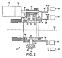
2つのクラッチパックの起動を制御する制御部材は、図1および図2において全体的に10で示されている。図2からわかるように、クラッチパックは同軸であって、それにより内側クラッチ50と外側クラッチ52を画定している。クラッチ50、52は、車両の差動アセンブリ内でブレーキとして使用される。したがって、アセンブリ10は車輪の駆動軸の両側の速度またはトルクを選択的に制御する。
A control member for controlling the activation of the two clutch packs is indicated generally at 10 in FIGS. As can be seen from FIG. 2, the clutch pack is coaxial, thereby defining an
アセンブリ10はモータ12と遊星ギヤボックス14の形式の減速機を含み、それはピニオン16をベアリング18内で回転させる入力部として働く。周知の構造の外部駆動構成22を持つウォームホイール20がピニオン16に、共に回転するために固定して取り付けられている。
The
外側歯状突起26を持つ環状ギヤホイール24の形式のトランスミッション部材は、ウォームホイール20と係合して作動する。特に、ウォームホイール20上の駆動構成22はギヤホイール24上の歯状突起26と噛み合い、それによりウォームホイール20の回転が、図2の28で示された中心軸の周りでのギヤホイール24の回転を引き起こす。歯状突起はトランスミッション部材の内面に形成されても外面に形成されてもよい。
A transmission member in the form of an
アセンブリ10は一対の駆動ピン30の形式の駆動部材を具え、それはギヤホイール24から半径方向に互いに対蹠的に突き出している。駆動ピン30はベアリング32に回転自在に取り付けられている。
The
アセンブリ10はさらに、固定管状部材38の両側に配置された一対の同軸管状ピストン34、36の形式の制御部材を含む。ピストン34、36は、例えばピン54によって、相対的な回転、ギヤホイール24および固定部材38に対する回転に抗して固定されている。しかし、ピストン34、36はギヤホイール24の回転軸に沿って互いに線状に移動する。
The
各ピストン34、36は互いに対蹠的に配置された一対のスロット40を含む。スロット40はそれぞれの駆動ピン30の末端部を受け入れるために配設されている。したがって固定部材38は、駆動ピン30が固定部材38を貫通して最も内側のピストン36まで延出することを可能にするスロット(図示せず)をも含むことが理解されよう。
Each
図1と図2には示していないが、スロット40は駆動ピン30によって係合されるカム面を画定する。本発明で使用されるカム断面の例が図3に示されており、そこで各スロットは傾斜面42、44、46、48を画定している。以下により詳しく説明されるように、ベアリングを担持する駆動ピン30は、ギヤホイール24の所定方向への回転時に、対応する傾斜面に係合させられる。
Although not shown in FIGS. 1 and 2, the
アセンブリ10は、以下のように、2つのクラッチパック50、52に個別にかかる力を制御する。
The
ギヤホイール24を右回りに回転させるべくモータ12が駆動されると、ギヤホイール24上のピン30は内側ピストン36内のスロット40のカム面44、48と係合させられる。ピストン36は回転可能に固定されているため、ギヤホイール24の回転時の駆動ピン30とカム面の係合は、内側ピストン36を固定部材38内で前方に、図1で見ると右方向に摺動させ、それにより内側クラッチ50内で出力クランプ力を発生させる。
When the
しかし、代わりにギヤホイール24をまず左回りに回転させるようにモータ12が駆動されると、ピン30は外側ピストン34内のスロット40のカム面42、46と係合させられることになる。ピストン34は回転できないため、再びギヤホイール24の回転時の駆動ピン30とカム面42、46の係合は、外側ピストン34を固定部材38上で、図1で見ると右方向に摺動させ、それにより外側クラッチ52内でクランプ力を発生させる。
However, instead, when the
典型的には、ギヤホイール24は、ピストン34、36を介して力が全く伝達されていない通常の静止位置からそれぞれの方向に45度回転させられる。理解されるように、アセンブリ10を用いてクラッチ50、52両方に同時にクランプ力を発生させることは不可能である。
Typically, the
なお、カム面にはPTFEコーティングなどの低摩擦コーティングを施してもよい。 The cam surface may be provided with a low friction coating such as PTFE coating.
この装置は車軸の両側で車輪間のトルクバイアスを制御する車両の差動構成での使用に有利に適する。一例が図4に示され、そこでアセンブリは、出願人の同時係属中の国際特許出願PCT/GB2005/002956号の図23に説明される類のトランスミッション・ハウジング60の一端に取り付けられている。ピストン34、36とギヤホイール24は同軸であり、トランスミッションの出力軸開口62に対応する環状であり、クラッチ50、52もまた出力軸に対応する環状であって、ハウジング60の左端に取り付けられている。差動モジュールがトランスミッション・ハウジング60の右端に取り付けられ、ギヤモジュールがクラッチ50、52と差動モジュールの間に配置された状態である。図1の固定部材38はトランスミッション・ハウジング60内へと延出し、両クラッチ50、52の接地素子として働く。したがってアセンブリ10は、トランスミッション・ハウジング60内でクラッチ50、52の制動効果を制御する小型電気機械式起動モジュールを提供する。
This device is advantageously suitable for use in a vehicle differential arrangement that controls the torque bias between the wheels on either side of the axle. An example is shown in FIG. 4, where the assembly is attached to one end of a transmission housing 60 of the kind described in FIG. 23 of applicant's co-pending international patent application PCT / GB2005 / 002956. The
アセンブリ10は例えば車両の駆動系統などの他のオンデマンド・カップリングにも適している。
The
アセンブリ10は、例えばポテンショメーターエンコーダを含む連続位置センサ、離散的位置センサ、温度センサ、圧力センサ、力センサ、および磁歪、磁気抵抗および表面音響波を含むトルクセンサなどのセンサを含むことが好ましい。
The
ECU制御ユニット(図示せず)はセンサからの信号をモニタし、記憶したアルゴリズムを適用して、それにより2つのクラッチ50、52のいずれかの起動を調節する。
An ECU control unit (not shown) monitors the signal from the sensor and applies a stored algorithm, thereby adjusting the activation of either of the two
別の構成が図5の70で概括的に示されている。 Another configuration is shown generally at 70 in FIG.
構成70は第1出力装置を駆動する第1ピストン72と、第2出力装置を駆動する第2のピストン74を含む。図5から明確にわかるように、第2のピストン74は第1ピストン72と同軸で内側に配置されている。 Configuration 70 includes a first piston 72 that drives the first output device and a second piston 74 that drives the second output device. As can be clearly seen from FIG. 5, the second piston 74 is arranged coaxially with the first piston 72 on the inside.
使用時、ピストン72と74はハウジング(図示せず)内および/またはハウジング上に取り付けられ、両ピストン72、74が前記ハウジングに対して軸方向に往復運動するように配置された状態となっている。より詳細には、リングギヤの、或いは、例えば図1から図4を参照して上記に説明した類の他の同様な駆動構成の相対回転運動に応答して、ピストン72、74は、図5では左から右に見られる軸方向への相対的な運動をする。 In use, the pistons 72 and 74 are mounted in and / or on a housing (not shown) and the pistons 72 and 74 are arranged to reciprocate axially relative to the housing. Yes. More particularly, in response to the relative rotational movement of the ring gear or other similar drive configuration of the kind described above with reference to FIGS. 1-4, for example, the pistons 72, 74 are shown in FIG. Relative movement in the axial direction seen from left to right.
ピストン72、74は、互いに相対的に回転することや、ピストンのハウジングに対して回転することは防止され、軸方向のみに動くようになっている。例えば、軸方向のみにピストン72、74の相対運動を可能にするために、例えば外側ピストン72は内側ピストンの内面上の溝に摺動自在に受け入れられるキーを含んでもよいし、またはその逆でもよい。類似した構成が、外側ピストン72とハウジングとの間、および/または内側ピストン74と、内側ピストン74の内側に配置された別の固定部材との間に配設されることができる。 The pistons 72 and 74 are prevented from rotating relative to each other and from rotating relative to the piston housing, and move only in the axial direction. For example, to allow relative movement of the pistons 72, 74 only in the axial direction, for example, the outer piston 72 may include a key that is slidably received in a groove on the inner surface of the inner piston, or vice versa. Good. Similar configurations can be disposed between the outer piston 72 and the housing and / or between the inner piston 74 and another securing member disposed inside the inner piston 74.
各ピストン72、74は、図5に示すように、その第1の端部から左に延出する一対の対蹠的に対向した制御部76を具えた略管状の胴部75を画定する。 As shown in FIG. 5, each piston 72, 74 defines a generally tubular body 75 with a pair of opposingly opposed controls 76 extending left from its first end.
外側ピストン72上の制御部76A、76Bは外側ピストン72の胴部75Aから半径方向にずれており、その結果胴部に対して概ね内向きに延びる。したがって、制御部76A、76Bは胴部75Aの外径より小さい外径を画定する。
The
内側ピストン74上の制御部76C、76Dは、胴部75Bの外径と同一な外径を画定するために胴部75Bと同延である。
The
図5からわかるように、外側ピストン72上の制御部76A、76Bによって画定される外径は、内側ピストン74上の制御部76C、76Dの外径と等しい。したがって、制御部76A、76Bが制御部76C、76Dの間に配置されて、この4つの制御部は同じ周縁を画定する。
As can be seen from FIG. 5, the outer diameter defined by the
なお、内側ピストン74は、一対の対蹠的に対向するくぼみを画定するものであり、図5ではその一方のみを78として見ることができる。くぼみ78は内側ピストン74の胴部75内に軸方向に延在し、外側ピストン72の内向きの制御部76A、76Bを、内側ピストン74に当接せずに内側ピストン74に対して軸方向に、図5で見ると右方向に動かすように構成されている。特に、各くぼみ78は対応する制御部76A、76Bと整列しており、その結果制御部76A、76Bは図5に示す位置から右方向に軸方向に動かされた場合にくぼみ78内を移動できる。
The inner piston 74 defines a pair of oppositely facing recesses, and only one of them can be seen as 78 in FIG. The indentation 78 extends axially into the body 75 of the inner piston 74, and the inward control portions 76 </ b> A and 76 </ b> B of the outer piston 72 are axially directed against the inner piston 74 without contacting the inner piston 74. In addition, it is configured to move in the right direction when viewed in FIG. In particular, each indentation 78 is aligned with a
各制御部76は、例えば図1から図4を参照して上記に説明した種の駆動ピンなどの駆動部材を受け入れるように構成された制御軌道を含む。 Each controller 76 includes a control track configured to receive a drive member, such as a drive pin of the type described above with reference to FIGS. 1-4, for example.
この実施形態において、制御軌道はスロット80の形をとる。各スロットは出入り口82を画定し、そこで内側ピストン74上のスロット80の出入り口82は、図5から明確にわかるように、外側ピストン72上のスロット80の出入り口82と半径方向に対向するように配置される。
In this embodiment, the control trajectory takes the form of a slot 80. Each slot defines an entry /
以下により詳細に説明するように、各スロット80はそれぞれのピストン72、74を軸方向に動かすように、駆動部材によって係合されるカム面84を画定する。 As will be described in more detail below, each slot 80 defines a cam surface 84 that is engaged by a drive member to move the respective piston 72, 74 in the axial direction.
好適な一実施形態において、構成70は図1から図4のリングギヤ24と連通して、つまり、リングギヤから延出する一対の対蹠的に対向した駆動ピンで取り付けられている。通常の休止状態では、リングギヤ上の駆動ピンはスロット80の対向したそれぞれの出入り口82の間で受動位置をとり、するとリングギヤとピストン72、74の間で軸方向の駆動力は伝達されない。しかし、リングギヤが所定の方向に回転すると、各駆動ピンは対応するスロット80の中へと動かされ、カム面84の第1の部分、例えばスロット80の出入り口82に直に隣接したカム面84の部分に係合させられる。同じ方向に回転が続けられると、駆動ピンは、それぞれのカム面84と係合しながらそれらの対応するスロット80沿いに進行し、最終的に駆動ピンはスロット80の端に当接する。その段階でリングギヤのそれ以上の回転は阻止される。
In one preferred embodiment, the configuration 70 is in communication with the
カム面84の配置は、リングギヤの回転中の駆動ピンとの係合が、前記ピストン72、74のうちいずれかを、他方のピストン72、74いずれかに対して軸方向に動かすようになっている。したがって、一度にピストン72、74のうち1つのみを動かすことができる。 The cam surface 84 is arranged such that engagement of the ring gear with the driving pin during rotation moves either of the pistons 72 and 74 in the axial direction with respect to either of the other pistons 72 and 74. . Thus, only one of the pistons 72, 74 can be moved at a time.
この実施形態において、スロット82は、一対の対向するカム面を画定するために両面となっている。すなわち、それぞれのピストン72、74の作用方向(図5で見ると右向き)への運動のための駆動面84と、ピストン72、74の戻り方向(図5で見ると左向き)への運動のための戻り面86である。
In this embodiment, the
したがって、リングギヤの第1方向への回転時、前記ピストンのうち1つは、駆動ピンと前記ピストンの駆動面84の間に伝達される力によって作用方向に動かされる。次にリングギヤが同量分逆方向に回転された場合、駆動ピンはピストンを元の位置に戻すためにそれぞれのピストンの戻り面86を係合する。リングギヤが前記逆方向への回転を続けると、次に駆動ピンを他方のピストンの駆動面84に係合させ、前記他方のピストンを作用方向に動かし、その後も同様に続く。 Therefore, when the ring gear rotates in the first direction, one of the pistons is moved in the direction of action by the force transmitted between the drive pin and the drive surface 84 of the piston. If the ring gear is then rotated in the opposite direction by the same amount, the drive pin engages the return surface 86 of each piston to return the piston to its original position. As the ring gear continues to rotate in the reverse direction, the drive pin is then engaged with the drive surface 84 of the other piston, moving the other piston in the direction of action, and so on.
構成70は、リングギヤが対応する方向へ45度回転した後で、各ピストンの作用方向への最大移動が達成されるように作動することが好ましく、逆もまた同様である。 Configuration 70 preferably operates so that maximum movement in the direction of action of each piston is achieved after the ring gear has rotated 45 degrees in the corresponding direction, and vice versa.
カム面84、86は、必要に応じて制御部材からの出力を調節するために、ピストンの軸方向移動の速さを変えるまたは中断するように構成されることができる。
一対の同軸多板湿式クラッチの起動を調節するために用いられるカム構成の一例が、図6に、概括的に90と表示して模式的に示されている。
The cam surfaces 84, 86 can be configured to change or interrupt the speed of the axial movement of the piston in order to adjust the output from the control member as needed.
An example of a cam configuration used to adjust the activation of a pair of coaxial multi-plate wet clutches is schematically shown in FIG.
一対の対向するカムスロット92、94が示され、そこで1つのスロット92は第1ピストン上に配置されるためのものであり、他方のスロット94は第2のピストン上に配置されるためのものである。第1ピストンは外側クラッチパックを起動するように作動するためのものであり、第2のピストンは、内側クラッチパックを起動するように作動するためのものである。2つのスロット92、94は左右対称であり、それぞれが出入り口96、略水平移動部分98、第1傾斜移動部分100、第2傾斜移動部分102および端面104を持つ。さらに、スロット92、94はそれぞれ駆動面106と戻り面108を画定する。
A pair of opposing cam slots 92, 94 are shown, where one slot 92 is for placement on the first piston and the other slot 94 is for placement on the second piston. It is. The first piston is for actuating to activate the outer clutch pack, and the second piston is for actuating to activate the inner clutch pack. The two slots 92 and 94 are symmetric, and each has an entrance / exit 96, a substantially horizontal moving
スロット92、94の幅は、例えば図1から図4を参照して上記に説明した種の、リングギヤに取り付けられた駆動ピン100の端部を受け入れるように構成されている。
The width of the slots 92, 94 is configured to receive the end of the
使用時、駆動ピン110はリングギヤの第1方向への回転により、図6に見られるスロット92、94のうち一方の出入り口96に入って左または右に行く。リングギヤが回転するにつれ、駆動ピ110は前記スロット内を端面104に達するまで動かされ、端面に達すると駆動ピン110のそれ以上の回転は制止される。
In use, the
端面104までの移動中に駆動ピン110はまず水平移動部分98に沿って通過する。それぞれのピストンを作用方向に動かさないように、この運動時には駆動面106に実質的な力は伝えられないことが理解されよう。水平移動部分98はしたがって、例えば車両が起伏の多い地形を移動している場合などの外部の刺激によるピストンの意図的でない起動を防止するために配設された「ホールドオフ」区域として働く。
During the movement to the
ピン110が第1傾斜移動部分100に進入すると、駆動面106と係合させられる。ピストンは回転可能に固定されているため、ピストンは駆動ピンから伝わる力によって作用方向に軸方向に変位する。
When the
第1傾斜移動部分100は、駆動ピン110がギヤホイールの第1方向への回転中に、ピストンの軸方向変位を起こすために駆動面106に常に力を伝えながら通過しなければならない斜面を画定する。図の通り斜面は比較的急勾配であり、それが軸方向変位の迅速な発生を確実にする。使用時、この急勾配区分は、それぞれのクラッチパック内のクラッチ板の間に遊びがある場合、クラッチパックに負荷が伝えられる前にそれを素早く吸収するために利用される。
The first inclined moving
リングギヤが第1方向へ続けて回転すると、駆動ピン110をスロット92の第2傾斜移動部分102に進入させる。図の通り、第2傾斜移動部分102もまた、ピン110が通過しなければならない斜面を画定する。しかし、ピストンの軸方向変位の速度を落とすために、そのランプ角は第1傾斜移動部分100のランプ角よりも少ない。軸方向変位の速度を落とすと、ピストンからの負荷をクラッチパックに制御しつつ伝えることが可能になる。
When the ring gear continues to rotate in the first direction, the
図の通り、第1傾斜移動部分100と第2傾斜移動部分102の間にはカーブした移行部があり、その結果、吸収段階と負荷段階の間で軸方向変位の変化速度を制御して、クラッチパックの起動時の衝撃を低減するようになっている。
As shown in the figure, there is a curved transition between the first inclined moving
クラッチパックの負荷を解放することが望まれる場合、リングギヤは、2つのスロット92、94の間の通常の静止位置まで駆動ピン110をスロット92に沿って戻すために、逆方向に回転されなければならない。
If it is desired to release the clutch pack load, the ring gear must be rotated in the reverse direction to return the
駆動ピン110はスロット92に沿って戻り、第2傾斜移動部分102および第1傾斜移動部分100それぞれの戻り面106を係合し、それがピストンを逆方向に軸方向変位させる。勾配がより緩やかな区分では、クラッチパックの負荷は制御されながら解放される。ピン110が水平移動部分に進入すると、ピン110はピストンが戻り方向にそれ以上は軸方向変位しないように、戻り面106を係合解除する。
The
この軸方向変位の工程は、リングギヤが逆方向へ回転する時の他のスロット94に関しても同様であることが理解されよう。 It will be appreciated that this axial displacement process is similar for the other slots 94 as the ring gear rotates in the opposite direction.
第1ピストン上のカム面の構成は、必要に応じて他のピストン上のカム面と違えてもよいことが理解されよう。実際、どのような所与のピストンの戻り面とも断面が異なる駆動面を具えることが好ましいといえよう。 It will be appreciated that the configuration of the cam surface on the first piston may be different from the cam surfaces on the other pistons if desired. In fact, it may be preferable to have a drive surface that has a different cross-section than the return surface of any given piston.
説明された構成は上記に説明した種の同軸クラッチへの適用に限定されず、自動車テクノロジーでの使用にも限定されない。特に軸方向の起動または運動、そしてより特定的には高いアクチュエータ力要求を持つ、様々な種類の出力装置の起動を制御するためにこの構成は適用されることができることが理解されよう。これらは例えば電気式機械の形をとることができる。この構成は、同軸でも他の配置構成でもよい2つの油圧式ピストンのストロークを、各ピストンの一部に結合されるか、或いは各ピストンの一部からなるそれぞれの出力部で制御して、その2つのピストンの運動を制御するために利用されることができる。この構成は双クラッチトランスミッション(DCT)に用いられることもでき、その場合一方のクラッチの変調は他方の起動の前に完了する。他の複式制動・クラッチングまたはクランピングアプリケーションに関しては当業者ならば容易に分かるであろう。 The described configuration is not limited to application to the type of coaxial clutch described above, nor is it limited to use in automotive technology. It will be appreciated that this configuration can be applied to control the activation of various types of output devices, particularly with axial activation or motion, and more particularly with high actuator force requirements. These can take the form of electric machines, for example. In this configuration, the strokes of two hydraulic pistons, which may be coaxial or in other arrangements, are coupled to a part of each piston or controlled by a respective output part consisting of a part of each piston. It can be used to control the movement of the two pistons. This configuration can also be used in a dual clutch transmission (DCT), in which case the modulation of one clutch is completed before the other is activated. Those skilled in the art will readily recognize other duplex braking / clutching or clamping applications.
この構成は、それらが単一の入力機構を用いて作動できるということに利点がある。好ましくは入力部は、例えばブラシまたはブラシレスDCタイプのモータなどの少なくとも1つの回転モータを備え、遊星ギヤボックス、ウォームおよびホイールギヤ入力部などの減速装置を含んでよい。入力部は例えば電気式、油圧式または空気圧式モータであってよい。 This configuration has the advantage that they can be operated using a single input mechanism. Preferably, the input unit comprises at least one rotary motor, such as a brush or brushless DC type motor, for example, and may include speed reducers such as planetary gearboxes, worm and wheel gear input units. The input unit may be, for example, an electric, hydraulic or pneumatic motor.
この構成は、単一の出力部の起動のための単一の制御部材のみを含み、そこで制御部材は少なくとも1つの駆動部材に、その軸方向変位のために係合される。 This configuration includes only a single control member for activation of a single output, where the control member is engaged to at least one drive member for its axial displacement.
トランスミッション部材は非環状装置の形をとることができ、それは例えば平面のギヤホイールの扇形部分であって、それは軸の周りを旋回し、前記軸は好ましくは制御部材と同軸である。 The transmission member may take the form of a non-annular device, for example a fan-shaped part of a planar gear wheel, which pivots about an axis, said axis preferably being coaxial with the control member.
各駆動部材はトランスミッション部材に結合された、または装着されたボール型またはローラー型要素の形をとることができ、各制御部材上のカム軌道内に可動に受け入れられるように構成される。別法として駆動部材は、例えばトランスミッション部材上に一体形成された歯状突起または突耳の形をとることができる。 Each drive member may take the form of a ball-type or roller-type element coupled to or attached to the transmission member and is configured to be movably received within a cam track on each control member. Alternatively, the drive member can take the form of, for example, a dent or lug integrally formed on the transmission member.
ボールタイプの駆動要素を利用する制御部材の実施形態は、図7に概略的に120と表示して示されている。 An embodiment of a control member that utilizes a ball-type drive element is shown schematically as 120 in FIG.
制御部材120は、概ね本出願人の同時係属中の国際特許出願PCT/GB2005/002956号に説明され、本発明の図4に示されている種類の可変トルクバイアス装置122と連通して示されている。概して、可変トルクバイアス装置122の内部構成要素は示されていない。しかし、図7でわかるように、可変トルクバイアス装置122は一対の同軸多板クラッチ、内側クラッチ124および外側クラッチ126を含む。前の実施形態と同様に、制御部材120は前記クラッチ124、126の作動を制御する。
制御部材120は可変トルクバイアス装置122の開放端上に、クラッチ126、128に隣接して搭載されたハウジング128を含む。ハウジング128は第1チャンバ130を画定し、環状トランスミッション部材132はその第1チャンバ130に回転自在に取り付けられている。使用時、トランスミッション部材132は、例えばモータなどの単一の被駆動入力部(図示せず)に、その回転を引き起こすために作動的に結合されている。
The
ハウジング128は第2チャンバ134を画定し、それは第1チャンバ130とは間隔が開いており、可変トルクバイアス装置122の開放端の上に配置されている。
The
トランスミッション部材132は管状シャフト部分135を含み、その導入部分(135Aで示す)は第2チャンバ134内に軸方向に延びる。環状板136の形式の駆動制御部材は、トランスミッション部材132の導入部分134Aとともに回転するように結合されており、その結果第2チャンバ134内で回転可能になる。駆動プレート136は、ボール140の形式の駆動部材の一部を受け入れるようにそれぞれが構成された複数のくぼみ138を画定する。
制御部材120はそれぞれのクラッチ124、126を起動するため、ハウジング128に対して軸方向に変位するように配置された一対の同軸制御部材142、144を含む。
The
各制御部材142、144は駆動プレート136の反対側に配置された制御面146を具える。各制御面146は対応する駆動ボール140の一部を受け入れる環状溝148を画定する。図7に示す通常の静止位置において、制御部材142、144の制御面146は略共面であって、その結果駆動ボール140を間に保持しながら駆動プレート136から均一に間を空けた状態となる。駆動プレート136は軸方向の動きに抗して実質的に固定され、ボール140は、駆動プレート136内のくぼみ138と、それぞれの対向する制御部材142、144内の溝148の間に回転自在に受け入れられている。
Each
駆動ボール140は本質的に駆動プレート136とともに回転するように配置されながら、それぞれの制御部材142、144の制御面146との接触を保っている。
The
しかし、制御面146内の溝148は、駆動プレート136の回転中に、それぞれのボール140がそれに沿って移動することができる略波状の軌道を形成するために、複数の傾斜区分を持つカム軌道を画定する。
However, the groove 148 in the
駆動プレート136が回転すると、ボール140はそれらの対応するくぼみ138内で同じ回転方向に移動させられる。ボール140がカム軌道内で上傾した区分に遭遇した場合、対応するクラッチパックに負荷を増加させるためにそれぞれの制御部材142、144を、作用方向すなわち図7に示す左方向に軸方向変位させる。ボール140がカム軌道内で下傾した区分に遭遇した場合、それぞれの制御部材142、144は軸方向変位することはなく、したがってクラッチパック上の負荷に変化はない。しかし、アセンブリに戻りばね構成(例えばクラッチアセンブリの周知の構成などの)が組み込まれている場合、制御部材は、それぞれのカム軌道内で下傾した区分に遭遇した場合、対応するクラッチパックの負荷を低減または解放するために、図7に示す左方向に、軸方向の解放方向に変位する。
As the
カム軌道は、駆動プレート136の第1の回転方向への回転が外側制御部材の軸方向変位を引き起こし、駆動プレート136の、前記第1の回転方向とは逆の第2の回転方向への回転が内側制御部材の軸方向変位を引き起こすように構成されている。したがって、内側クラッチと外側クラッチの起動は相互排他的である。
In the cam track, rotation of the
カム軌道の波状断面は、それぞれのクラッチの調節要求によって必要に応じ構成されることができる。 The wavy cross-section of the cam track can be configured as required by the respective clutch adjustment requirements.
なお、図1から図6の制御アセンブリは、可変トルクバイアス装置内の一対の同軸クラッチとの対応する連通のために、図7に概括的に示された種のハウジング内に作動的に搭載されていてもよい。 It should be noted that the control assembly of FIGS. 1-6 is operatively mounted in a housing of the type generally shown in FIG. 7 for corresponding communication with a pair of coaxial clutches in the variable torque bias device. It may be.
Claims (23)
Applications Claiming Priority (3)
| Application Number | Priority Date | Filing Date | Title |
|---|---|---|---|
| GB0519546A GB0519546D0 (en) | 2005-09-26 | 2005-09-26 | Control assembly |
| GB0521627A GB0521627D0 (en) | 2005-10-24 | 2005-10-24 | Control assembly |
| PCT/GB2006/003539 WO2007034208A1 (en) | 2005-09-26 | 2006-09-25 | Control assembly |
Publications (2)
| Publication Number | Publication Date |
|---|---|
| JP2009510353A true JP2009510353A (en) | 2009-03-12 |
| JP2009510353A5 JP2009510353A5 (en) | 2009-04-23 |
Family
ID=37517171
Family Applications (1)
| Application Number | Title | Priority Date | Filing Date |
|---|---|---|---|
| JP2008532856A Pending JP2009510353A (en) | 2005-09-26 | 2006-09-25 | Control assembly |
Country Status (4)
| Country | Link |
|---|---|
| US (1) | US20100219034A1 (en) |
| EP (1) | EP1937990A1 (en) |
| JP (1) | JP2009510353A (en) |
| WO (1) | WO2007034208A1 (en) |
Cited By (3)
| Publication number | Priority date | Publication date | Assignee | Title |
|---|---|---|---|---|
| WO2013122179A1 (en) * | 2012-02-17 | 2013-08-22 | 株式会社エクセディ | Actuator for twin clutch device |
| JP2014521032A (en) * | 2011-07-13 | 2014-08-25 | ダイムラー・アクチェンゲゼルシャフト | Engagement clutch actuator for automobile transmission |
| US11892063B2 (en) | 2019-10-18 | 2024-02-06 | Höhn Gmbh | Two-speed transmission for an electric drive system, and drive system including such a two-speed transmission |
Families Citing this family (17)
| Publication number | Priority date | Publication date | Assignee | Title |
|---|---|---|---|---|
| DE102007034568A1 (en) * | 2007-07-25 | 2009-01-29 | Bayerische Motoren Werke Aktiengesellschaft | Vehicle with a transmission and a clutch assembly |
| DE102008013054B4 (en) * | 2008-03-06 | 2010-04-22 | Getrag Getriebe- Und Zahnradfabrik Hermann Hagenmeyer Gmbh & Cie Kg | Actuation mechanism for engaging and disengaging a separating clutch with a turnable segment |
| US8231492B2 (en) * | 2009-04-16 | 2012-07-31 | GM Global Technology Operations LLC | Torque transmitting device |
| DE102010037317B4 (en) * | 2010-09-03 | 2017-05-04 | FEV Europe GmbH | Actuator for actuating a clutch assembly |
| DE102011007266B4 (en) | 2011-04-13 | 2019-02-28 | Schaeffler Technologies AG & Co. KG | Switching device with a coupling device |
| DE102012220073A1 (en) * | 2012-11-05 | 2014-05-08 | Schaeffler Technologies Gmbh & Co. Kg | Electromechanical clutch actuating system for actuating single or dual clutch, has non-contact torque sensor device for detecting rotational torque applied to electro-motor-driven shaft, when clutch is actuated |
| WO2014172274A1 (en) | 2013-04-15 | 2014-10-23 | Gkn Driveline North America, Inc. | Shift collar assembly for a power transfer unit |
| US9360270B2 (en) | 2013-08-21 | 2016-06-07 | Raytheon Company | Launcher with multi-part pusher, and method |
| DE102013224805A1 (en) * | 2013-12-04 | 2015-06-11 | Robert Bosch Gmbh | Device for actuating a hydraulic piston for an electrically actuated clutch of a motor vehicle |
| US10731716B2 (en) | 2015-09-09 | 2020-08-04 | Ntn Corporation | Automatic clutch device |
| US9976605B2 (en) * | 2015-12-22 | 2018-05-22 | Dana Automotive Systems Group, Llc | Dual ramp actuator controlling a two clutch system for a driveline |
| US10253861B2 (en) | 2016-01-21 | 2019-04-09 | Dana Automotive Systems, Group, Llc | Torque vectoring unit |
| JP6735180B2 (en) * | 2016-03-04 | 2020-08-05 | ジーケーエヌ オートモーティブ リミテッド | A cam mechanism and a clutch device using this cam mechanism. |
| US10473168B2 (en) | 2016-09-16 | 2019-11-12 | Dana Automotive System Group, Llc | Ball retaining ball and ramp assembly |
| CN106763293A (en) * | 2016-12-05 | 2017-05-31 | 北京科技大学 | A kind of moment of torsion transmits control device |
| KR102560515B1 (en) * | 2017-05-03 | 2023-07-28 | 섀플러 테크놀로지스 아게 운트 코. 카게 | shifting device |
| DE102019100978B3 (en) * | 2019-01-16 | 2020-03-05 | Schaeffler Technologies AG & Co. KG | Device for synchronizing and / or shifting in a transmission housing and transmission |
Citations (2)
| Publication number | Priority date | Publication date | Assignee | Title |
|---|---|---|---|---|
| JPH03103668A (en) * | 1989-08-31 | 1991-04-30 | Gkn Automot Ag | Power change gear |
| JPH05345535A (en) * | 1992-06-15 | 1993-12-27 | Mitsubishi Motors Corp | Right and left drive force adjusting device for vehicle |
Family Cites Families (15)
| Publication number | Priority date | Publication date | Assignee | Title |
|---|---|---|---|---|
| US1643055A (en) * | 1925-12-31 | 1927-09-20 | Adolphus S Butell | Transmission |
| DE662848C (en) * | 1936-05-17 | 1938-07-22 | Bernhard Jansen Dr Ing | Double-acting friction clutch, especially for gear change transmissions of motor vehicles |
| US3179220A (en) * | 1962-04-06 | 1965-04-20 | Dana Corp | Clutch actuating mechanism |
| US3313170A (en) * | 1964-08-10 | 1967-04-11 | Gen Dynamics Corp | Electromechanical actuator |
| HU201832B (en) * | 1987-03-26 | 1990-12-28 | Magyar Vagon Es Gepgyar | Running gear of adjustable wheel track having equalizing gear and epicyclic gear drive |
| JPH0599300A (en) * | 1991-03-01 | 1993-04-20 | Gkn Automot Ag | Transmission which receive load and can be shifted |
| US5545103A (en) * | 1994-08-01 | 1996-08-13 | Dana Corporation | Vehicle transfer case with dual electrically-actuated magnetic clutches |
| US5862705A (en) * | 1997-08-13 | 1999-01-26 | Lee; Chi-Nan | Speed transferring system for a lathe |
| US6012561A (en) * | 1998-09-15 | 2000-01-11 | Chrysler Corporation | Dual clutch design for and electro-mechanical automatic transmission having a dual input shaft |
| JP3660603B2 (en) * | 2000-04-07 | 2005-06-15 | ジー・ケー・エヌ・ヴィスコドライヴ・ゲゼルシャフト・ミット・ベシュレンクテル・ハフツング | Axial direction setting device |
| GB2386653B (en) * | 2002-03-22 | 2005-06-29 | Gkn Technology Ltd | Differential gear |
| US6805653B2 (en) * | 2002-08-02 | 2004-10-19 | Visteon Global Technologies, Inc. | Selectively controlled limited slip differential |
| DE10303831A1 (en) * | 2003-01-30 | 2004-08-12 | Jegel, Franz Peter, Ing. | Lamella coupling, especially for motor vehicles, has inner lamellas pressed against outer lamellas by engagement movable only axially ring that slides along inclined plane on rotatable switching ring |
| DE102004023792A1 (en) * | 2004-05-07 | 2005-12-08 | Hofer Mechatronic Gmbh | Coupling device of a gear arrangement of a vehicle, preferably a motor vehicle |
| EP1610021A1 (en) * | 2004-06-21 | 2005-12-28 | LuK Lamellen und Kupplungsbau Beteiligungs KG | System for torque transmission device |
-
2006
- 2006-09-25 EP EP06779536A patent/EP1937990A1/en not_active Withdrawn
- 2006-09-25 JP JP2008532856A patent/JP2009510353A/en active Pending
- 2006-09-25 US US12/067,135 patent/US20100219034A1/en not_active Abandoned
- 2006-09-25 WO PCT/GB2006/003539 patent/WO2007034208A1/en active Application Filing
Patent Citations (2)
| Publication number | Priority date | Publication date | Assignee | Title |
|---|---|---|---|---|
| JPH03103668A (en) * | 1989-08-31 | 1991-04-30 | Gkn Automot Ag | Power change gear |
| JPH05345535A (en) * | 1992-06-15 | 1993-12-27 | Mitsubishi Motors Corp | Right and left drive force adjusting device for vehicle |
Cited By (7)
| Publication number | Priority date | Publication date | Assignee | Title |
|---|---|---|---|---|
| JP2014521032A (en) * | 2011-07-13 | 2014-08-25 | ダイムラー・アクチェンゲゼルシャフト | Engagement clutch actuator for automobile transmission |
| US9322439B2 (en) | 2011-07-13 | 2016-04-26 | Daimler Ag | Form-fit coupling actuating device of a motor vehicle transmission |
| WO2013122179A1 (en) * | 2012-02-17 | 2013-08-22 | 株式会社エクセディ | Actuator for twin clutch device |
| JP2013167338A (en) * | 2012-02-17 | 2013-08-29 | Exedy Corp | Actuator for twin clutch device |
| CN104114894A (en) * | 2012-02-17 | 2014-10-22 | 株式会社艾科赛迪 | Actuator for twin clutch device |
| US9109643B2 (en) | 2012-02-17 | 2015-08-18 | Exedy Corporation | Actuator for twin clutch device |
| US11892063B2 (en) | 2019-10-18 | 2024-02-06 | Höhn Gmbh | Two-speed transmission for an electric drive system, and drive system including such a two-speed transmission |
Also Published As
| Publication number | Publication date |
|---|---|
| US20100219034A1 (en) | 2010-09-02 |
| WO2007034208A1 (en) | 2007-03-29 |
| EP1937990A1 (en) | 2008-07-02 |
Similar Documents
| Publication | Publication Date | Title |
|---|---|---|
| JP2009510353A (en) | Control assembly | |
| JP6548831B2 (en) | Clutch assembly with ball cam unit and method of controlling a clutch assembly | |
| JP4958015B2 (en) | Electric disc brake | |
| US6802794B2 (en) | Single actuator lost motion shift assembly | |
| KR101982690B1 (en) | Differential limiting device for vehicle | |
| JP5409804B2 (en) | Drive assembly | |
| CN101273212A (en) | Control assembly | |
| JP5135226B2 (en) | Differential device having two axial adjustment devices operated together | |
| JP2010169248A (en) | Disk brake | |
| JP5093476B2 (en) | Electric disc brake | |
| JP2002168321A (en) | Locking differential assembly | |
| JP2009510353A5 (en) | ||
| JP2007132517A (en) | Ball ramp device with variable pitch of ball groove | |
| JPH034055A (en) | Differential device | |
| WO2004065815A1 (en) | Actuator and brake device | |
| JP2004138131A (en) | Operating device for synchro-mechanism in power train in automobile | |
| US10118484B2 (en) | Transfer | |
| CN111637219B (en) | Actuator of transfer case | |
| JP2007078134A (en) | Driving force distribution device | |
| US5934433A (en) | Friction clutch having an actuator for automated operation | |
| JP2005321031A (en) | Actuator | |
| JP2007131194A (en) | Drive force distribution device for four-wheel drive vehicle | |
| JP7230684B2 (en) | Power transmission path switching device and two-speed transmission | |
| JP6644524B2 (en) | Electric brake device | |
| US7086976B2 (en) | Electric motor applied clutch with a drag torque actuator |
Legal Events
| Date | Code | Title | Description |
|---|---|---|---|
| A521 | Written amendment |
Free format text: JAPANESE INTERMEDIATE CODE: A523 Effective date: 20090220 |
|
| A621 | Written request for application examination |
Free format text: JAPANESE INTERMEDIATE CODE: A621 Effective date: 20090909 |
|
| A131 | Notification of reasons for refusal |
Free format text: JAPANESE INTERMEDIATE CODE: A131 Effective date: 20120313 |
|
| A02 | Decision of refusal |
Free format text: JAPANESE INTERMEDIATE CODE: A02 Effective date: 20120807 |