EP0574752B1 - Key and corresponding lock cylinder especially a profile lock cylinder - Google Patents
Key and corresponding lock cylinder especially a profile lock cylinder Download PDFInfo
- Publication number
- EP0574752B1 EP0574752B1 EP93108541A EP93108541A EP0574752B1 EP 0574752 B1 EP0574752 B1 EP 0574752B1 EP 93108541 A EP93108541 A EP 93108541A EP 93108541 A EP93108541 A EP 93108541A EP 0574752 B1 EP0574752 B1 EP 0574752B1
- Authority
- EP
- European Patent Office
- Prior art keywords
- key
- fork
- profile
- cylinder
- channel
- Prior art date
- Legal status (The legal status is an assumption and is not a legal conclusion. Google has not performed a legal analysis and makes no representation as to the accuracy of the status listed.)
- Expired - Lifetime
Links
Images


Classifications
-
- E—FIXED CONSTRUCTIONS
- E05—LOCKS; KEYS; WINDOW OR DOOR FITTINGS; SAFES
- E05B—LOCKS; ACCESSORIES THEREFOR; HANDCUFFS
- E05B19/00—Keys; Accessories therefor
- E05B19/0017—Key profiles
- E05B19/0029—Key profiles characterized by varying cross-sections of different keys within a lock system
-
- E—FIXED CONSTRUCTIONS
- E05—LOCKS; KEYS; WINDOW OR DOOR FITTINGS; SAFES
- E05B—LOCKS; ACCESSORIES THEREFOR; HANDCUFFS
- E05B31/00—Cylinder locks with both tumbler pins or balls and plate tumblers
-
- E—FIXED CONSTRUCTIONS
- E05—LOCKS; KEYS; WINDOW OR DOOR FITTINGS; SAFES
- E05B—LOCKS; ACCESSORIES THEREFOR; HANDCUFFS
- E05B35/00—Locks for use with special keys or a plurality of keys ; keys therefor
- E05B35/003—Locks for use with special keys or a plurality of keys ; keys therefor for keys with movable bits
Definitions
- the invention relates to a key according to the preamble of claim 1 and a lockable with it, with a correspondingly profiled key channel containing all-round closed cylinder core and radially adjustable pin tumblers, especially profile lock cylinder, according to the preamble of claim 6, the key being one Key shaft made of solid material, which has a substantially circularly profiled, massive incision area provided with notches for the pin tumblers, and a radially projecting longitudinal web for guiding and driving.
- the longitudinal web used for guiding and driving is designed as a simple or also slightly profiled longitudinal rib, which optionally also runs slightly helically and can be provided with additional incisions for controlling further tumblers.
- the invention is based on the object of improving a key and a locking cylinder of the type mentioned at the outset in such a way that, while maintaining the essentially circular-cylindrical cross section of the key shaft and key channel and thereby making it possible to accommodate numerous pin tumblers, their misuse by corresponding pseudo- Raw keys significantly more difficult and at the same time the stability of the keys in their longitudinal web area is significantly increased.
- the longitudinal web of the key shaft has a fork-shaped profile, the fork legs of which have a common, narrow Fork neck are connected to the round incision area of the key shaft and have between their free ends a fork channel to be passed through by a corresponding key channel profile projection of the cylinder core.
- the fork-shaped profiled longitudinal web preferably has a Y-shaped profile, the support leg of which corresponds to the fork neck and the expansion leg of which correspond to the two fork legs which run obliquely to one another.
- a key for locking cylinders with a key channel freely opening outward into the core circumference, which can be different in its shaft area adjoining the flat-shaped, flat-walled key back, including a Y-shaped profile.
- this key is foreign to the genre, especially since its Y-shaped profiled shaft area has the key incisions in the form of notch incisions sitting on the individual web or rib ends of the Y profile, while the key back adjoining the Y profile area is free of key incisions.
- the width of the fork neck is approximately one third of the diameter of the round incision area of the key, whereas the height of the fork neck is smaller and approximately equal to the thickness of the fork legs, the depth of the fork groove and the Distance between the outer surfaces of the fork legs inclined like a roof at an angle of about 60 ° and the inclined plane running parallel to them and through the center of the incision area.
- the key can also be provided at the level of its fork groove with one or more bores penetrating the key shaft diametrically and with limitedly adjustable stylus pins which, in themselves, e.g. are known from EP 0 154 755, and have additional notches for further pin tumblers at the bore ends opposite the fork groove, the maximum length of the stylus pins being no greater than the height extension of the key shaft less the depth of the fork groove. This creates additional locking options while at the same time further increasing security against improper use of keys and the corresponding locking cylinder.
- the lock cylinder to be properly actuated by the key according to the invention is conventionally provided with a profile cylinder housing and a cylinder core which is rotatably mounted in its circular cylindrical area and can be locked by means of radially adjustable pin tumblers for guiding and turning the key.
- the cylinder core in the longitudinal groove region of its key channel has a fork, in particular a Y-shaped profile, which is forked in accordance with the longitudinal web of the key, with a profile projection protruding between the two channel groove legs formed in this way, at least one further extending in a transverse one segment-shaped Circumferential recess of the cylinder core radially adjustable, the two channel groove legs and the intervening profile projection of the key channel crossing tumbler plate is provided, which is supported with its core rounded to the rear on a spring-loaded locking pin mounted in the cylinder housing web and which due to its radial adjustment a locking of the Cylinder core.
- This tumbler plate which therefore crosses both channel groove legs and the intermediate profile projection of the key channel, must be acted upon by both fork legs of the appropriate key for its correct adjustment to its core release position.
- Misuse by a key that is identical in terms of its incision area, but only provided with a simple, radially short longitudinal web, is therefore not possible, nor is it possible with the help of a key, the fork leg of which would be ground down, because this would result in a cantilever-like tilting of the key Locking plate could come, especially if the latter is provided on the underside with a support lug over which it is supported on its locking pin in the manner of a balance bar.
- the tumbler plate is advantageously profiled in a U-shape on its upper side facing the key channel, with its projecting ends on both sides of the upper middle section crossing the two channel groove legs and the profile projection lying therebetween projecting into the displacement path of adjacent tumbler elements in the locked position of the tumbler plate and thus allowing them to be blocked.
- the tumbler plate is provided in the middle of its upper middle part crossing the two channel groove legs with a tactile nose which can be acted upon by the stylus of the key and which lies profile-wise within the key channel profile projection, with the diagonally opposite side then also in the cylinder housing and cylinder core, another protruding into the key channel Pin tumbler is provided for the control of the stylus.
- a similarly shaped profile plate can be provided in a segment-shaped core circumferential recess, which is provided on the inside of its projecting ends with profile projections to be varied, the profile grooves of which on the outside in the area of the two fork legs of the key to be correspondingly incorporated, to be varied can be provided.
- the tumbler plates can also have a cylindrical middle part provided with wing attachments on both sides, which is provided on its upper side facing the key channel with a run-on slope for the key stylus.
- the tumbler plates and the circumferential recesses provided on the cylinder core and receiving them can also be designed correspondingly obliquely.
- the lock cylinder key shown in FIGS. 1 and 2 has a key shaft 1 made of solid material, which has a substantially circularly profiled massive incision area 2, on the circumference of which is offset both in the longitudinal and in the circumferential direction, numerous notches 3 for the actuation of in associated locking cylinder located, radially adjustable pin tumblers are incorporated.
- the circular-cylindrical incision area 2 is laterally adjoined in the shaft area of the key, the longitudinal web generally designated 4.
- This longitudinal web 4 has a fork-shaped, in particular Y-shaped profile, the fork legs 5,5 'of which are connected to the round incision area 2 of the key shaft via a common narrow fork neck 5' '.
- a fork groove 5' '' to be passed through by a corresponding key channel profile projection of the cylinder core.
- the main leg of the Y-shaped profile of this key longitudinal web 4 corresponds to the fork neck 5 ′′, while the spreading legs of the Y profile correspond to the two fork legs 5.5 ′ that run obliquely to one another.
- the key shown in FIG. 1 in a natural size is preferably designed in its shaft area in such a way that that the width B of the fork neck 5 '' is approximately one third of the diameter D of the round incision area 2, whereas the height H of the fork neck 5 '' is smaller and approximately equal to the thickness d of the fork legs 5.5 ', the depth T of the fork groove 5 '''and the distance A between the outer surfaces of the fork legs 5,5' inclined towards each other at an angle ⁇ of approximately 60 ° and the inclined plane E running to them and through the center of the incision area 2.
- the locking cylinder key shown in FIG. 3 substantially matches the profile of the key shaft 1 'described above. It differs from this, however, in that it is provided at the level of its fork groove 5 '' 'with one or more holes 6 diametrically penetrating the key shaft 1' and therein there are adjustable adjustable stylus pins 7, and additional holes at its opposite ends of the fork groove 5 '' ' Has notches 3 'for further pin tumblers.
- the maximum length of the stylus (s) 7 is not greater than the height S of the key shaft 1 or 1 'reduced by the depth T of the fork groove 5' '' (see FIG. 1).
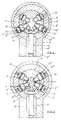
- the locking cylinder shown in FIGS. 4 and 5, which fits the key according to FIGS. 1 and 2, has in a conventional manner a profile cylinder housing 8 and a cylinder core 9 which is rotatably mounted in its circular cylindrical region 8 'and which is generally designated 10 by means of radially adjustable Pin tumblers can be blocked.
- the cylinder core 9 is closed all around and has an axis-centered key channel 11 of essentially circular cross-section with a channel longitudinal groove adjoining it laterally, generally designated 12, for guiding and driving the key.
- the key channel 11 has in its longitudinal groove area 12 a fork, in particular Y-shaped, corresponding to the longitudinal web 4 of the key shown in FIGS. 1 and 2, that is to say two channel groove legs 12 ', 12''and a profile projection 12' projecting between them. owns.
- the cylinder core with a transverse, Provided segment-shaped circumferential recess 13, in the radially adjustable a tumbler plate 14 is provided which crosses the two channel groove legs 12 ', 12''and the profile projection 12'''. This is supported with its rounded rear side corresponding to the core circumference 9 'on a locking pin 15 which is mounted in the cylinder housing web 8''in a corresponding bore 8''' and is under the action of the spring 16.
- the tumbler plate 14 is profiled in a U-shape on its top side facing the key channel 11, its projecting ends 14 'lying on both sides of the top middle part 14' crossing the two channel groove legs 12 ', 12' 'and the profile projection 12' '' 'protrude into the shifting path of adjacent tumbler elements 10' or 10 '' in the engaged locking position of the tumbler plate 14 shown in FIG. 4 and are therefore able to block them.
- the tumbler plate 14 is moved by inserting the appropriate key 1 through its two spread fork legs 5, 5 'into the illustrated release position, which releases the cylinder core 9, while at the same time pressing the locking pin 15 back accordingly suitably arranged notches 3, the pin tumblers 10 have been radially adjusted so that they also release the cylinder core 9 for its rotary adjustment movement with their paired tumbler pins 10 ''', 10 IV .
- the sectional locking cylinder shown in FIG. 6 corresponds in all details to the one described above.
- a wrong key 1 ′′ that is to say provided with a Y-shaped profiled longitudinal web
- a wrong key 1 ′′ namely with a shortened simple longitudinal web 4 ′
- the tumbler plate 14 cannot be moved into its release position according to FIG. 5. Rather, it remains under the action of the locking pin 15 in its illustrated locking position in which it is at the same time the neighboring tumblers 10 'and 10''are still blocked.
- the profile locking cylinder shown in section in Figure 7 differs from the ones described above only in the slightly different nature of its tumbler plate 14 '''.
- it is provided on the underside with a support lug 14 IV , by means of which it is supported on its locking pin 15 in the manner of a balance beam.
- the key 1 '''introduced here has a solid circular cylindrical cross section corresponding to the keys obtained above, but differs from this in that it only has one fork leg 5' in its longitudinal web region, the other fork leg 5 is therefore missing.
- the tumbler plate 14 '' is also still acted upon by the remaining fork leg 5 ', but is tilted in the manner shown, in which it at least also lock pin 15 with its support nose 14''' is able to partially push back into a possible release position, but not the adjacent pin tumbler 10 ', since it still protrudes with its projecting end 14''in its sliding path and thereby blocks it.
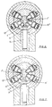
- the sectional locking cylinder shown in FIGS. 8 and 9 is essentially of the above-described nature, that is to say also provided with a plurality of radially adjustable tumblers 10 and a correspondingly profiled key channel 11 with two channel groove legs 12 ', 12''forming the longitudinal channel groove.
- this locking cylinder since it is intended for a key provided with a stylus 7 according to FIG. 3, also has a further radially adjustable pin tumbler 10 V for controlling the stylus 7 in the key shaft 1 'and a correspondingly modified tumbler plate 14 V. Mistake.
- FIGS. 8 and 9 show a profile locking cylinder of the nature shown in FIGS. 8 and 9, but when inserting a key 1 that is not suitable in this case because it is provided without a stylus 7. Both of its fork legs 5, 5 'are here because of the greater recess on the upper side Tumbler plate 14 V is unable to move the latter into its release position.
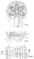
- a profile plate 19 can also be provided, which is provided on the inside of its ends 19 'projecting on the top side with profile projections 19''to be varied, in which case in the area of the two fork legs 5, 5 'of the key corresponding profile grooves can be incorporated, so that by creating differently profiled tumbler plates in a technically simple manner, corresponding profile differences can also be realized, for example for locking systems.
- FIG. 11 shows a profile plate 19 'projecting on the top side with profile projections 19''to be varied, in which case in the area of the two fork legs 5, 5 'of the key corresponding profile grooves can be incorporated, so that by creating differently profiled tumbler plates in a technically simple manner, corresponding profile differences can also be realized, for example for locking systems.
- FIG. 12 shows that in the case of pin tumblers 10 which are axially offset from one another, for example in a helical arrangement, the tumbler plate 14 V or the profiled plate 19 and the circumferential recesses 13 which are provided on the cylinder core 9 and which receive them can be designed correspondingly obliquely.
- FIG. 12 also shows that the tumbler plate 14 V here has a wing attachment on both sides 14 VII provided cylindrical middle part 14 VIII , which can be provided on its upper side facing the key channel 11 with opposing run-up slopes 14 IX for the key stylus 7. If the wing attachments 14 VII lie at right angles to the cylindrical central part 14 VIII , that is to say protrude radially from them, two profile differences can be achieved by turning the tumbler plates 14 through 180 ° with each of them.
- a plurality of axially successive tumbler plates 14 can be provided in the locking cylinder, which can be displaced into the release position by the fork legs 5, 5 'of the matching locking cylinder.
- a plurality of stylus pins 7 can also be provided in the key shaft 1 'and in the lock cylinder a plurality of additional pin tumblers 17 correspondingly to be assigned for the control of the stylus pins and their own control by the stylus pins.
Abstract
Description
Die Erfindung bezieht sich auf einen Schlüssel nach dem Oberbegriff des Anspruchs 1 sowie einen damit schließbaren, mit einem einen entsprechend profilierten Schlüsselkanal enthaltenden, ringsum geschlossenen Zylinderkern und radial verstellbaren Stiftzuhaltungen versehenen Schließzylinder, insbesondere Profilschließzylinder, nach dem Oberbegriff des Anspruchs 6, wobei der Schlüssel einen aus Vollmaterial bestehenden Schlüsselschaft besitzt, der einen im wesentlichen kreisrund profilierten, mit an seinem Umfang eingearbeiteten Einkerbungen für die Stiftzuhaltungen versehenen, massiven Einschnittbereich sowie einen daraus radial vorspringenden Längssteg für die Führung und Drehmitnahme aufweist.The invention relates to a key according to the preamble of
Schlüssel und dazu passende Schließzylinder obiger Art sind durch die australische Patentschrift AU-B-485 117 (Anmeldung Nr. 69 965 174) sowie die deutsche Patentschrift 817 409 bekannt. Der bei diesen Zylinderschlüsseln vorhandene, im wesentlichen kreisrund profilierte massive Einschnittbereich erlaubt es, auf ihm in Längs- wie in Umfangsrichtung zahlreiche Einkerbungen für die im mit einem entsprechenden Schlüsselkanal versehenen Zylinderkern und dem letzteren umgebenden Zylindergehäuse untergebrachten Stiftzuhaltungen einzuarbeiten, wohingegen der am Schlüsselschaft vorhandene Längssteg im Zusammenwirken mit der am Zylinderkern vorhandenen, an dessen kreiszylindrischen Schlüsselkanalbereich seitlich angrenzenden Kanallängsnut für die ordnungsgemäße Führung des Schlüssels und auch eine hinreichende Drehmitnahme zwischen Schlüssel und Zylinderkern sorgt. Im Gegensatz zu den mit einem in den Kernumfang ausmündenden Schlüsselkanal ausgerüsteten Schließzylindern wie z.B. nach der DE 4 000 179 A1 wird durch die radial entsprechend kürzere Bemessung der Kanallängsnut und des darin hineinpassenden Schlüssel-Längssteges gewährleistet, daß nicht allzu große Drehmomente zwischen Zylinderkern und Einsteckteil auftreten können, die etwa beim unbefugten Einsetzen eines rohschlüsselartigen Fremdkörpers zum Abscheren der Zuhaltungselemente und damit zum Aufbrechen des Zylinderkerns führen könnten. Bei den bekannten gattungsmäßigen Schlüsseln ist der zur Führung und Drehmitnahme dienende Längssteg als einfache oder auch leicht profilierte Längsrippe ausgebildet, die gegebenenfalls auch leicht schraubenlinienförmig verlaufen und mit zusätzlichen Einschnitten für die Steuerung weiterer Zuhaltungen versehen sein kann. Dadurch ist aber immer noch keine ausreichende Sicherheit gegen unbefugtes Öffnen des Zylinderschlosses gegeben, weil diese Schlüssel auf relativ einfache Weise durch Pseudo-Rohschlüssel ersetzt werden können. Dafür wäre beispielsweise ein im Durchmesser auf den kreiszylindrischen Teil des Schlüsselkanals solcher Schließzylinder angepaßter Rundstab ausreichend, der an seiner Spitze mit einer Fase versehen und in den radial zwei Stifte, z.B. Spiralspannstifte eingesetzt wären, wobei der eine Stift zur Übertragung des Drehmoments und der andere Stift zum Anschlagen an der Stirnfläche des Zylinderkerns dienen und so die axiale Einschubposition des Pseudo-Schlüssels festlegen könnte.Keys and matching locking cylinders of the above type are known from the Australian patent AU-B-485 117 (application no. 69 965 174) and the German patent 817 409. The substantially circularly profiled massive incision area available with these cylinder keys allows numerous notches to be incorporated in the longitudinal and circumferential directions for the pin tumblers accommodated in the corresponding key channel and the cylinder housing surrounding the latter, whereas the longitudinal web on the key shaft in the Interaction with the existing longitudinal channel groove on the cylinder core, on its circular cylindrical key channel area, ensures the proper guidance of the key and also sufficient rotational driving between the key and the cylinder core. In contrast to the locking cylinders equipped with a key channel opening into the core circumference, such as after
Der Erfindung liegt die Aufgabe zugrunde, einen Schlüssel sowie einen dadurch zu schließenden Schließzylinder der eingangs erwähnten Gattung dahingehend zu verbessern, daß mit ihnen unter Beibehalt des im wesentlichen kreiszylindrischen Querschnitts von Schlüsselschaft und Schlüsselkanal und dadurch ermöglichter Unterbringung zahlreicher Stiftzuhaltungen deren mißbräuchliche Benutzung durch entsprechende Pseudo-Rohschlüssel wesentlich erschwert und zugleich die Stabilität der Schlüssel in ihrem Längsstegbereich noch erheblich gesteigert wird.The invention is based on the object of improving a key and a locking cylinder of the type mentioned at the outset in such a way that, while maintaining the essentially circular-cylindrical cross section of the key shaft and key channel and thereby making it possible to accommodate numerous pin tumblers, their misuse by corresponding pseudo- Raw keys significantly more difficult and at the same time the stability of the keys in their longitudinal web area is significantly increased.
Diese Aufgabe wird ausgehend von einem gattungsgemäß beschaffenen Schlüssel erfindungsgemäß dadurch gelöst, daß der Längssteg des Schlüsselschafts ein gabelförmiges Profil besitzt, dessen Gabelschenkel über einen gemeinsamen, schmalen Gabelhals mit dem runden Einschnittbereich des Schlüsselschaftes verbunden sind und zwischen ihren freien Enden eine von einem entsprechenden Schlüsselkanal-Profilvorsprung des Zylinderkerns zu durchfahrende Gabelrinne aufweisen. Vorzugsweise besitzt der gabelförmig profilierte Längssteg ein Y-förmiges Profil, dessen Standbein dem Gabelhals und dessen Spreizschenkel den beiden entsprechend schräg zueinander verlaufenden Gabelschenkeln entsprechen.This object is achieved on the basis of a key of the generic type according to the invention in that the longitudinal web of the key shaft has a fork-shaped profile, the fork legs of which have a common, narrow Fork neck are connected to the round incision area of the key shaft and have between their free ends a fork channel to be passed through by a corresponding key channel profile projection of the cylinder core. The fork-shaped profiled longitudinal web preferably has a Y-shaped profile, the support leg of which corresponds to the fork neck and the expansion leg of which correspond to the two fork legs which run obliquely to one another.
Für einen so beschaffenen Schlüssel ist charakteristisch, daß er mit seinen beiden zum gabelförmig profilierten Längssteg gehörenden Gabelschenkeln gemeinsam auf ein im Schließzylinderkern untergebrachtes Zuhaltungselement einwirken kann und zu dessen ordnungsgemäßer Überführung in seine Kern-Freigabeposition auch einwirken muß. Dadurch wird die Sicherheit des entsprechend beschaffenen Schließzylinders gegen mißbräuchliches Aufsperren etwa mittels nachgeahmter Pseudo-Schlüssel wesentlich erhöht. Da die beiden Gabelschenkel lediglich über ihren vergleichsweise schmalen Gabelhals mit dem massiven im wesentlichen kreisrund profilierten Einschnittbereich des Schlüsselschaftes verbunden sind, wird die Unterbringungsmöglichkeit von zahlreichen Einkerbungen im Einschnittbereich dadurch nicht verringert. Weiterhin wird durch die Gabel-, insbesondere Y-förmige Profilierung des Schlüssel-Längssteges das Widerstandsmoment des Schlüssels beträchtlich vergrößert, so daß der Schlüssel also auch stabiler gegen Verdrehen oder Verbiegen wird.It is characteristic of a key obtained in this way that it can act with its two fork legs belonging to the fork-shaped longitudinal web jointly on a tumbler element housed in the lock cylinder core and must also act for its proper transfer into its core release position. This significantly increases the security of the appropriately designed locking cylinder against improper unlocking, for example by means of imitated pseudo keys. Since the two fork legs are connected to the solid, essentially circularly profiled incision area of the key shaft only via their comparatively narrow fork neck, the possibility of accommodating numerous notches in the incision area is not thereby reduced. Furthermore, the moment of resistance of the key is considerably increased by the fork, in particular Y-shaped profiling of the key longitudinal web, so that the key is also more stable against twisting or bending.
Durch die FR-PS 512 631 ist ein für Schließzylinder mit einem nach außen in den Kernumfang frei ausmündenden Schlüsselkanal bestimmter Schlüssel bekannt, der in seinem an den flach ausgebildeten, beiderseits flachwandigen Schlüsselrücken anschließenden Schaftbereich verschiedenartig, darunter auch Y-förmig profiliert sein kann. Dieser Schlüssel ist aber gattungsfremd, zumal sein Y-förmig profilierter Schaftbereich die Schlüsseleinschnitte in Form von an den einzelnen Steg- bzw. Rippenenden des Y-Profils sitzenden Kerbeinschnitten aufweist, während der an den Y-Profilbereich anschließende Schlüsselrücken frei von Schlüsseleinschnitten ist.From FR-PS 512 631, a key is known for locking cylinders with a key channel freely opening outward into the core circumference, which can be different in its shaft area adjoining the flat-shaped, flat-walled key back, including a Y-shaped profile. However, this key is foreign to the genre, especially since its Y-shaped profiled shaft area has the key incisions in the form of notch incisions sitting on the individual web or rib ends of the Y profile, while the key back adjoining the Y profile area is free of key incisions.
Als besonders vorteilhaft hat es sich bei dem erfindungsgemäß beschaffenen Schlüssel erwiesen, wenn die Breite des Gabelhalses etwa ein Drittel des Durchmessers des runden Einschnittbereichs des Schlüssels beträgt, dagegen die Höhe des Gabelhalses kleiner und etwa gleich der Dicke der Gabelschenkel, der Tiefe der Gabelrinne sowie dem Abstand zwischen den dachartig zueinander unter einem Winkel von etwa 60° geneigten Außenflächen der Gabelschenkel und der zu ihnen parallel und durch das Zentrum des Einschnittbereichs verlaufenden Schrägebene ist.It has proven to be particularly advantageous in the key obtained according to the invention if the width of the fork neck is approximately one third of the diameter of the round incision area of the key, whereas the height of the fork neck is smaller and approximately equal to the thickness of the fork legs, the depth of the fork groove and the Distance between the outer surfaces of the fork legs inclined like a roof at an angle of about 60 ° and the inclined plane running parallel to them and through the center of the incision area.
Nach einem weiteren Merkmal der Erfindung kann der Schlüssel in Höhe seiner Gabelrinne auch mit einem oder mehreren den Schlüsselschaft diametral durchdringenden Bohrungen und darin begrenzt verstellbar lagernden Taststiften versehen sein, die an sich z.B. durch die EP 0 154 755 bekannt sind, sowie an den der Gabelrinne gegenüberliegenden Bohrungsenden zusätzliche Einkerbungen für weitere Stiftzuhaltungen aufweisen, wobei die maximale Länge der Taststifte nicht größer als die Höhenerstreckung des Schlüsselschaftes vermindert um die Tiefe der Gabelrinne ist. Hierdurch werden weitere Zuhaltungsmöglichkeiten geschaffen bei zugleich weiterer Erhöhung der Sicherheit gegen mißbräuchliche Benutzung von Schlüssel und dazu passendem Schließzylinder.According to a further feature of the invention, the key can also be provided at the level of its fork groove with one or more bores penetrating the key shaft diametrically and with limitedly adjustable stylus pins which, in themselves, e.g. are known from EP 0 154 755, and have additional notches for further pin tumblers at the bore ends opposite the fork groove, the maximum length of the stylus pins being no greater than the height extension of the key shaft less the depth of the fork groove. This creates additional locking options while at the same time further increasing security against improper use of keys and the corresponding locking cylinder.
Der durch den erfindungsgemäß geschaffenen Schlüssel ordnungsgemäß zu betätigende Schließzylinder ist herkömmlicherweise mit einem Profilzylindergehäuse und einem in dessen kreiszylindrischen Bereich drehverstellbar gelagerten, mittels radial verstellbarer Stiftzuhaltungen blockierbaren, ringsum geschlossenen Zylinderkern versehen, der einen achsmittig verlaufenden Schlüsselkanal von im wesentlichen kreisförmigem Querschnitt mit daran seitlich angrenzender Kanallängsnut für die Führung und Drehmitnahme des Schlüssels besitzt. Hiervon ausgehend weist nach einem weiteren Aspekt der Erfindung der Zylinderkern im Längsnutbereich seines Schlüsselkanals ein dem Längssteg des Schlüssels entsprechend gegabeltes, insbesondere Y-förmiges, Profil mit einem zwischen dessen beide, so gebildeten Kanalnutschenkel hineinragenden Profilvorsprung auf, wobei weiterhin mindestens ein in einer quer verlaufenden segmentförmigen Umfangsaussparung des Zylinderkerns radial verstellbar gelagertes, die beiden Kanalnutschenkel und den dazwischenliegenden Profilvorsprung des Schlüsselkanals querendes Zuhaltungsplättchen vorgesehen ist, das sich mit seiner dem Kernumfang entsprechend gerundeten Rückseite an einem im Zylindergehäusesteg gelagerten, unter Federwirkung stehenden Sperrstift abstützt und das infolge seiner radialen Verstellung eine Sperrung des Zylinderkerns hervorruft. Dieses Zuhaltungsplättchen, das also beide Kanalnutschenkel und den dazwischen liegenden Profilvorsprung des Schlüsselkanals quert, muß zu seiner ordnungsgemässen Verstellung in seine Kernfreigabestellung von beiden Gabelschenkeln des passenden Schlüssels beaufschlagt werden. Eine mißbräuchliche Benutzung durch einen zwar bezüglich seines Einschnittbereichs übereinstimmenden, jedoch lediglich mit einem einfachen radial kurzen Längssteg versehenen Schlüssel ist damit nicht möglich, desgleichen auch nicht mit Hilfe eines Schlüssels, dessen einer Gabelschenkel etwa abgeschliffen wäre, weil das dann zu einer waagebalkenartigen Verkantung des Schlüssel-Zuhaltungsplättchens kommen könnte, insbesondere wenn letzteres dafür unterseitig mit einer Stütznase versehen wird, über die es sich waagebalkenartig auf seinem Sperrstift abstützt.The lock cylinder to be properly actuated by the key according to the invention is conventionally provided with a profile cylinder housing and a cylinder core which is rotatably mounted in its circular cylindrical area and can be locked by means of radially adjustable pin tumblers for guiding and turning the key. Proceeding from this, according to a further aspect of the invention, the cylinder core in the longitudinal groove region of its key channel has a fork, in particular a Y-shaped profile, which is forked in accordance with the longitudinal web of the key, with a profile projection protruding between the two channel groove legs formed in this way, at least one further extending in a transverse one segment-shaped Circumferential recess of the cylinder core radially adjustable, the two channel groove legs and the intervening profile projection of the key channel crossing tumbler plate is provided, which is supported with its core rounded to the rear on a spring-loaded locking pin mounted in the cylinder housing web and which due to its radial adjustment a locking of the Cylinder core. This tumbler plate, which therefore crosses both channel groove legs and the intermediate profile projection of the key channel, must be acted upon by both fork legs of the appropriate key for its correct adjustment to its core release position. Misuse by a key that is identical in terms of its incision area, but only provided with a simple, radially short longitudinal web, is therefore not possible, nor is it possible with the help of a key, the fork leg of which would be ground down, because this would result in a cantilever-like tilting of the key Locking plate could come, especially if the latter is provided on the underside with a support lug over which it is supported on its locking pin in the manner of a balance bar.
Das Zuhaltungsplättchen ist auf seiner dem Schlüsselkanal zugewandten Oberseite vorteilhaft U-förmig profiliert, wobei seine zu beiden Seiten des die beiden Kanalnutschenkel sowie den dazwischen liegenden Profilvorsprung querenden Oberseiten-Mittelteils liegenden, vorspringenden Enden in der eingerückten Sperrstellung des Zuhaltungsplättchens in die Verschiebebahn benachbarter Zuhaltungselemente hineinragen und somit auch diese dadurch zu blockieren erlauben.The tumbler plate is advantageously profiled in a U-shape on its upper side facing the key channel, with its projecting ends on both sides of the upper middle section crossing the two channel groove legs and the profile projection lying therebetween projecting into the displacement path of adjacent tumbler elements in the locked position of the tumbler plate and thus allowing them to be blocked.
Für mit einem Taststift der vorbeschriebenen Art versehene Zylinderschlüssel ist das Zuhaltungsplättchen in der Mitte seines die beiden Kanalnutschenkel querenden Oberseiten-Mittelteils mit einer vom Taststift des Schlüssels beaufschlagbaren Tastnase versehen, die profilmäßig innerhalb des Schlüsselkanal-Profilvorsprungs liegt, wobei dann weiterhin auf der diagonal gegenüberliegenden Seite im Zylindergehäuse und Zylinderkern eine weitere, in den Schlüsselkanal hineinragende Stift-Zuhaltung für die Steuerung des Taststiftes vorgesehen ist.For cylinder keys provided with a stylus of the type described above, the tumbler plate is provided in the middle of its upper middle part crossing the two channel groove legs with a tactile nose which can be acted upon by the stylus of the key and which lies profile-wise within the key channel profile projection, with the diagonally opposite side then also in the cylinder housing and cylinder core, another protruding into the key channel Pin tumbler is provided for the control of the stylus.
In einer segmentförmigen Kern-Umfangssaussparung kann anstelle eines Zuhaltungsplättchens ein ähnlich gestaltetes Profilplättchen vorgesehen sein, das auf den Innenseiten seiner oberseitig vorspringenden Enden mit zu varrierenden Profilvorsprüngen versehen ist, denen schlüsselseitig im Bereich der beiden Gabelschenkel des Schlüssels auf deren Außenseiten entsprechend einzuarbeitende, zu variierende Profilnuten vorgesehen sein können.Instead of a tumbler plate, a similarly shaped profile plate can be provided in a segment-shaped core circumferential recess, which is provided on the inside of its projecting ends with profile projections to be varied, the profile grooves of which on the outside in the area of the two fork legs of the key to be correspondingly incorporated, to be varied can be provided.
Weiterhin können die Zuhaltungsplättchen auch einen mit beidseitigen Flügelansätzen versehenen zylindrischen Mittelteil besitzen, der auf seiner dem Schlüsselkanal zugewandten Oberseite mit einer Anlaufschräge für den Schlüssel-Taststift versehen ist.Furthermore, the tumbler plates can also have a cylindrical middle part provided with wing attachments on both sides, which is provided on its upper side facing the key channel with a run-on slope for the key stylus.
Sofern die Stiftzuhaltungen im Kern- und Zylindergehäuse axial versetzt zueinander, etwa schraubenlinienförmig angeordnet werden, können auch die Zuhaltungsplättchen und die sie aufnehmenden, am Zylinderkern vorgesehenen Umfangsaussparungen entsprechend schräg gestaltet sein.If the pin tumblers in the core and cylinder housings are arranged axially offset from one another, for example helically, the tumbler plates and the circumferential recesses provided on the cylinder core and receiving them can also be designed correspondingly obliquely.
In der Zeichnung sind mehrere Ausführungsbeispiele erfindungsgemäß ausgebildeter Schlüssel und zugehöriger Profilschließzylinder dargestellt. Dabei zeigen
- Fig.1 und 2
- eine erste Ausführungsform eines Schlüssels im Querschnitt seines Schafts und in der Seitenansicht,
- Fig.3
- einen mit einem oder mehreren Taststiften versehenen Schlüssel in der Seitenansicht,
- Fig.4 und 5
- den Querschnitt durch einen Profilschließzylinder bei abgezogenem bzw. eingestecktem Schlüssel der in den Fig.1 und 2 dargestellten Beschaffenheit,
- Fig.6
- den gleichen Schließzylinder im Querschnitt bei eingestecktem falschem Rohschlüssel,
- Fig.7
- einen Schnitt durch einen Schließzylinder mit abweichend beschaffenem Zuhaltungsplättchen und einem eingesteckten Schlüssel von wiederum falscher Beschaffenheit,
- Fig.8 und 9
- Querschnitte durch einen Schließzylinder mit bzw. ohne eingestecktem, mit Taststift versehenem Schlüssel,
- Fig.10
- einen Schnitt durch einen den Fig.8 und 9 entsprechenden Profilschließzylinder bei eingestecktem, ohne Taststift versehenem Schlüssel, und
- Fig.11
- einen Schnitt nach der Linie XI-XI der
- Fig.12,
- die eine quergeschnittene Draufsicht auf einen mit unterschiedlich beschaffenen Plättchen, nämlich einem Profil- und einem Zuhaltungsplättchen, versehenen Teilbereich eines Schließzylinders wiedergibt.
- Fig. 1 and 2
- a first embodiment of a key in cross section of its shaft and in side view,
- Fig. 3
- a side view of a key provided with one or more styli,
- Fig. 4 and 5
- the cross section through a profile lock cylinder with the key removed and inserted, of the nature shown in FIGS. 1 and 2,
- Fig. 6
- the same locking cylinder in cross-section with the wrong raw key inserted,
- Fig. 7
- a section through a locking cylinder with deviating procured tumbler plate and an inserted key of wrong quality,
- Fig. 8 and 9
- Cross-sections through a locking cylinder with or without a key inserted with a stylus,
- Fig. 10
- a section through a profile lock cylinder corresponding to FIGS. 8 and 9 when the key is inserted without a stylus, and
- Fig. 11
- a section along the line XI-XI the
- Fig.12,
- which reproduces a cross-sectional plan view of a portion of a locking cylinder provided with differently made plates, namely a profile plate and a tumbler plate.
Der in den Fig.1 und 2 dargestellte Schließzylinder-Schlüssel besitzt einen aus Vollmaterial bestehenden Schlüsselschaft 1, der einen im wesentlichen kreisrund profilierten massiven Einschnittbereich 2 aufweist, an dessen Umfang sowohl in Längs- als auch Umfangsrichtung versetzt zahlreiche Einkerbungen 3 für die Betätigung von im zugehörigen Schließzylinder befindlichen, radial verstellbaren Stiftzuhaltungen eingearbeitet sind. An den kreiszylindrischen Einschnittbereich 2 schließt sich im Schaftbereich des Schlüssels dessen generell mit 4 bezeichneter Längssteg seitlich an. Dieser Längssteg 4 besitzt ein gabelförmiges, insbesondere Y-förmiges Profil, dessen Gabelschenkel 5,5' über einen gemeinsamen schmalen Gabelhals 5'' mit dem runden Einschnittbereich 2 des Schlüsselschafts verbunden sind. Zwischen ihren freien Enden der Gabelschenkel 5,5' ist eine von einem entsprechenden Schlüsselkanal-Profilvorsprung des Zylinderkerns zu durchfahrende Gabelrinne 5''' vorgesehen. Von dem Y-förmigen Profil dieses Schlüssellängssteges 4 entspricht das Standbein dem Gabelhals 5'' während die Spreizschenkel des Y-Profils den beiden entsprechend schräg zueinander verlaufenden Gabelschenkeln 5,5' entsprechen.The lock cylinder key shown in FIGS. 1 and 2 has a
Der in Fig.1 in übernatürlicher Größe wiedergegebene Schlüssel ist in seinem Schaftbereich vorzugsweise so beschaffen, daß die Breite B des Gabelhalses 5'' etwa ein Drittel des Durchmessers D des runden Einschnittbereichs 2 beträgt, dagegen die Höhe H des Gabelhalses 5'' kleiner und etwa gleich der Dicke d der Gabelschenkel 5,5', der Tiefe T der Gabelrinne 5''' sowie dem Abstand A zwischen den dachartig zueinander unter einem Winkel α von etwa 60° geneigten Außenflächen der Gabelschenkel 5,5' und der zu ihnen und durch das Zentrum des Einschnittbereichs 2 verlaufenden Schrägebene E ist.The key shown in FIG. 1 in a supernatural size is preferably designed in its shaft area in such a way that that the width B of the fork neck 5 '' is approximately one third of the diameter D of the
Der in Fig.3 dargestellte Schließzylinder-Schlüssel stimmt im Profil seines Schlüsselschafts 1' wesentlich mit dem vorbeschriebenen Schlüssel überein. Er unterscheidet sich davon jedoch dadurch, daß er in Höhe seiner Gabelrinne 5''' mit einem oder mehreren den Schlüsselschaft 1' diametral durchdringenden Bohrungen 6 und darin begrenzt verstellbar lagernden Taststiften 7 versehen ist und an seinen der Gabelrinne 5''' gegenüberliegenden Bohrungsenden zusätzliche Einkerbungen 3' für weitere Stiftzuhaltungen aufweist. Die maximale Länge des oder der Taststifte 7 ist nicht größer als die Höhenerstreckung S des Schlüsselschaftes 1 bzw. 1' vermindert um die Tiefe T der Gabelrinne 5''' (vgl. Fig.1).The locking cylinder key shown in FIG. 3 substantially matches the profile of the key shaft 1 'described above. It differs from this, however, in that it is provided at the level of its fork groove 5 '' 'with one or
Der in den Fig.4 und 5 dargestellte, zum Schlüssel nach den Fig.1 und 2 passende Schließzylinder besitzt in herkömmlicher Weise ein Profilzylindergehäuse 8 und einen in dessen kreiszylindrischem Bereich 8' drehverstellbar gelagerten Zylinderkern 9, der mittels radial verstellbarer, generell mit 10 bezeichneter Stiftzuhaltungen blockierbar ist. Der Zylinderkern 9 ist ringsum geschlossen und besitzt einen achsmittig verlaufenden Schlüsselkanal 11 von im wesentlichen kreisförmigem Querschnitt mit einer daran seitlich angrenzenden, generell mit 12 bezeichneten Kanallängsnut für die Führung und Drehmitnahme des Schlüssels.The locking cylinder shown in FIGS. 4 and 5, which fits the key according to FIGS. 1 and 2, has in a conventional manner a
Erfindungsgemäß besitzt der Schlüsselkanal 11 in seinem Längsnutbereich 12 ein dem Längssteg 4 des in den Fig.1 und 2 abgebildeten Schlüssels entsprechend gegabeltes, insbesondere Y-förmiges Profil, das also zwei Kanalnutschenkel 12',12'' sowie einen zwischen diese hineinragenden Profilvorsprung 12''' besitzt. Weiterhin ist hier der Zylinderkern mit einer querverlaufenden, segmentförmigen Umfangsaussparung 13 versehen, in der radial verstellbar ein die beiden Kanalnutschenkel 12', 12'' sowie den Profilvorsprung 12''' querendes Zuhaltungsplättchen 14 vorgesehen ist. Dieses stützt sich mit seiner dem Kernumfang 9' entsprechend gerundeten Rückseite an einem im Zylindergehäusesteg 8'' in einer entsprechenden Bohrung 8''' gelagerten Sperrstift 15 ab, der unter Wirkung der Feder 16 steht.According to the invention, the
Das Zuhaltungsplättchen 14 ist auf seiner dem Schlüsselkanal 11 zugewandten Oberseite U-förmig profiliert, wobei seine zu beiden Seiten des die beiden Kanalnutschenkel 12',12'' und den Profilvorsprung 12''' querenden Oberseiten-Mittelteils 14' liegenden, vorspringenden Enden 14'' in der eingerückten, in Fig.4 dargestellten Sperrstellung des Zuhaltungsplättchens 14 in die Verschiebebahn benachbarter Zuhaltungselemente 10' bzw. 10'' hineinragen und daher diese zu blockieren vermögen.The
Wie Fig.5 zeigt, wird das Zuhaltungsplättchen 14 durch Einführen des passenden Schlüssels 1 durch dessen beide gespreizten Gabelschenkel 5,5' in die dargestellte, den Zylinderkern 9 freigebende Freigabeposition verschoben bei gleichzeitigem entsprechendem Zurückdrücken des Sperrstiftes 15. Gleichzeitig sind durch die im Schlüsselschaft 1 passend angeordneten Einkerbungen 3 die Stiftzuhaltungen 10 radial so verstellt worden, daß sie mit ihren paarweise aneinanderliegenden Zuhaltungsstiften 10''',10IV den Zylinderkern 9 für seine Drehverstellbewegung gleichfalls freigeben.As shown in FIG. 5, the
Der in Fig.6 im Schnitt dargestellte Profilschließzylinder entspricht in allen Einzelheiten dem vorbeschriebenen. Hier ist jedoch anstelle des passenden, also mit einem Y-förmig profilierten Längssteg versehenen Schlüssels ein falscher Schlüssel 1'', nämlich mit einem verkürzten einfachen Längssteg 4' versehener, in den Schlüsselkanal des Zylinderkerns eingeführt. Hierdurch kann daher das Zuhaltungsplättchen 14 nicht in seine Freigabestellung entsprechend Fig.5 verschoben werden. Es verbleibt vielmehr unter der Einwirkung des Sperrstiftes 15 in seiner dargestellten Sperrlage, in der es zugleich auch die benachbarten Zuhaltungen 10' und 10'' noch blockiert.The sectional locking cylinder shown in FIG. 6 corresponds in all details to the one described above. Here, however, instead of the appropriate key, that is to say provided with a Y-shaped profiled longitudinal web, a
Der in Fig.7 im Schnitt dargestellte Profilschließzylinder unterscheidet sich von den vorbeschriebenen nur durch die etwas andere Beschaffenheit seines Zuhaltungsplättchens 14'''. Es ist in diesem Falle unterseitig mit einer Stütznase 14IV versehen, über die es sich waagebalkenartig auf seinem Sperrstift 15 abstützt. Der hier eingeführte Schlüssel 1''' besitzt einen den vorstehend beschaffenen Schlüsseln entsprechenden massiven kreiszylindrischen Querschnitt, unterscheidet sich davon jedoch dadurch, daß er lediglich einen Gabelschenkel 5' in seinem Längsstegbereich aufweist, der andere Gabelschenkel 5 also fehlt. Wie Fig.7 zeigt, wird in diesem Falle durch den verbliebenen Gabelschenkel 5' das Zuhaltungsplättchen 14'' zwar auch noch beaufschlagt, jedoch in der dargestellten Weise verkantet, in der es zwar mit seiner Stütznase 14''' auch noch den Sperrstift 15 zumindest teilweise in eine etwaige Freigabestellung zurückzudrücken vermag, nicht jedoch die benachbarte Stiftzuhaltung 10', da es in deren Verschiebebahn mit seinem vorspringenden Ende 14'' nach wie vor hineinragt und sie dadurch blockiert.The profile locking cylinder shown in section in Figure 7 differs from the ones described above only in the slightly different nature of its tumbler plate 14 '''. In this case, it is provided on the underside with a
Der in den Fig.8 und 9 im Schnitt dargestellte Profilschließzylinder ist im wesentlichen von der vorbeschriebenen Beschaffenheit, also auch mit mehreren radial verstellbaren Zuhaltungen 10 und einem entsprechend profilierten Schlüsselkanal 11 mit zwei die Kanallängsnut bildenden Kanalnutschenkeln 12',12'' versehen. Zusätzlich ist dieser Schließzylinder aber, da er für einen mit Taststift 7 versehenen Schlüssel gemäß der Fig.3 bestimmt ist, noch mit einer weiteren radial verstellbaren Stiftzuhaltung 10V für die Steuerung des Taststiftes 7 im Schlüsselschaft 1' sowie mit einem entsprechend abgeänderten Zuhaltungsplättchen 14V versehen. Dieses weist nämlich in der Mitte seines die beiden Kanalnutschenkel 12', 12'' querenden Oberseiten-Mittelteils eine vom Taststift 7 des Schlüssels 1' beaufschlagbare Tastnase 14VI auf, die profilmäßig innerhalb des Schlüsselkanal-Profilvorsprungs 12''' liegt. In diesem Falle wird also das Zuhaltungsplättchen 14V nicht durch die Gabelschenkel 5,5' des Schlüssels, sondern durch dessen Taststift 7 in die in Fig.8 dargestellte Freigabestellung gedrückt, wobei der Taststift 7 durch die Zuhaltung 10V und deren stärker als die zum Sperrstift 15 gehörende Feder 16 bemessene Feder 17 in seine im Schlüssel 1' untere Freigabeposition verschoben worden ist. Die Begrenzung der Verstellbarkeit des Taststiftes 7 im Schaft 1' des Schlüssels erfolgt über im Gabelschenkelhals 5'' vorgesehene Sicken 18, die in die Verschiebebahn des Taststifts 7 im Bereich seines Halses 7' hineinragen. Es versteht sich, daß auch mehrere entsprechende Zuhaltungsplättchen 14 steuernde Taststifte 7 unterschiedlicher Länge vorgesehen sein können, denen entsprechend verschieden lange Zuhaltungsstifte 10V zuzuordnen wären. Die Fig.9 zeigt den Schließzylinder der Fig.8 bei abgezogenem Schlüssel, also in der Blockierposition seines Zylinderkerns 9.The sectional locking cylinder shown in FIGS. 8 and 9 is essentially of the above-described nature, that is to say also provided with a plurality of radially
Die Fig.10 zeigt einen Profilschließzylinder der in Fig.8 und 9 dargestellten Beschaffenheit, jedoch bei Einstecken eines in diesem Falle nicht passenden, weil ohne Taststift 7 versehenen Schlüssels 1. Dessen beide Gabelschenkel 5,5' sind hier wegen der stärkeren oberseitigen Austiefung des Zuhaltungsplättchens 14V nicht in der Lage, letzteres in seine Freigabeposition zu verschieben.10 shows a profile locking cylinder of the nature shown in FIGS. 8 and 9, but when inserting a key 1 that is not suitable in this case because it is provided without a
Wie die Fig.11 und 12 zeigen, kann auch anstelle eines Zuhaltungsplättchen 14 ein Profilplättchen 19 vorgesehen sein, das auf den Innenseiten seiner oberseitig vorspringenden Enden 19' mit zu variierenden Profilvorsprüngen 19'' versehen ist, wobei dann im Bereich der beiden Gabelschenkel 5,5' des Schlüssels entsprechende Profilnuten eingearbeitet werden können, so daß durch Anlegen unterschiedlich profilierter Zuhaltungsplättchen auf fertigungstechnisch einfache Weise auch entsprechende Profilverschiedenheiten etwa für Schließanlagen realisiert werden können. Weiterhin zeigt die Fig.12, daß bei axial versetzt zueinander, etwa schraubenlinig angeordneten Stiftzuhaltungen 10 die Zuhaltungsplättchen 14V oder das Profilplättchen 19 und die sie aufnehmenden, am Zylinderkern 9 vorgesehenen Umfangsaussparungen 13 entsprechend schräg gestaltet sein können. Auch zeigt die Fig.12, daß das Zuhaltungsplättchen 14V hier einen mit beidseitigen Flügelansätzen 14VII versehenen zylindrischen Mittelteil 14VIII besitzen kann, der auf seiner dem Schlüsselkanal 11 zugewandten Oberseite mit gegenüberliegenden Anlaufschrägen 14IX für den Schlüssel-Taststift 7 versehen sein kann. Wenn die Flügelansätze 14VII rechtwinklig zum zylindrischen Mittelteil 14VIII liegen, also dazu radial abstehen, können durch Wenden der Zuhaltungsplättchen 14 um 180° mit jedem von ihnen zwei Profilverschiedenheiten erreicht werden.As shown in FIGS. 11 and 12, instead of a
Es versteht sich, daß im Rahmen der vorliegenden Ansprüchen mancherlei Abwandlungen möglich sind. Insbesondere können im Schließzylinder mehrere axial hintereinanderliegende Zuhaltungsplättchen 14 vorgesehen sein, die durch die Gabelschenkel 5,5' des passenden Schließzylinders in Freigabestellung zu verschieben sind. Auch können mehrere Taststifte 7 im Schlüsselschaft 1' und im Schließzylinder mehrere entsprechend zuzuordnende zusätzliche Stiftzuhaltungen 17 für die Steuerung der Taststifte und ihre eigene Steuerung durch die Taststifte vorgesehen werden.It goes without saying that various modifications are possible within the scope of the present claims. In particular, a plurality of axially
Claims (12)
- A key for a locking cylinder, in particular a profile locking cylinder, provided with an enclosed cylinder core containing a correspondingly profiled key channel, and with radially adjustable pin tumblers, having a key shaft (1) consisting of solid material, which comprises a substantially circular profiled solid indented region (2) provided with indentations (3) worked on its surface for the pin tumblers (10), as well as a radially projecting longitudinal cross piece (4) for guidance and rotational entrainment, characterised in that the longitudinal cross piece (4) of the key shaft (1) has a fork-like profile, the limbs of which fork (5, 5') are connected to the round indented region (2) of the key shaft by means of a common, narrow fork neck (5'') and between their free ends comprise a fork trough (5''') through which a corresponding key channel profile projection (12''') of the cylinder core (9) passes.
- A key according to claim 1, characterised in that its fork-like profiled longitudinal cross piece (4) has a y-shaped profile of which the upright limb corresponds to the fork neck (5'') and of which the inclined limbs correspond to the two fork limbs (5, 5') which extend correspondingly inclined towards each other.
- A key according to claim 2, characterised in that the width (B) of the fork neck (5'') amounts to approximately one third of the diameter (D) of the round indented region (2), in contrast, the height (H) of the fork neck (5'') is smaller and approximately equal to the thickness (d) of the fork limbs (5, 5'), to the depth (T) of the fork trough (5''') and to the distance (A) between the roof-like outer surfaces of the fork limbs, which are inclined towards each other at an angle (α) of approximately 60°, and the inclined plane (E) extending parallel to the said outer surfaces and through the centre of the indented region (2).
- A key according to claim 2 or 3, characterised in that at the level of its fork trough (5''') it is provided with one or a plurality of bores (6) diametrically penetrating the key shaft (2) and with tracer pins (7) mounted therein in a limited adjustable manner, and comprises, at the ends of the bores lying opposite the fork trough (5'''), additional indentations (3') for further pin tumblers (10V), wherein the maximum length of the tracer pins (7) is not greater than the height extension (S) of the key shaft (2) reduced by the depth (T) of the fork trough (5''').
- A key according to one of claims 1 to 4, characterised in that in the region of its two fork limbs (5, 5') on the outsides thereof variable profile grooves are provided.
- A locking cylinder for keys according to one of claims 1 to 5, having a profile cylinder housing (8) and an enclosed cylinder core (9) which is mounted in a rotationally adjustable manner in the round cylindrical region (8') of the said housing and which can be blocked by means of radially adjustable pin tumblers, which cylinder core has a key channel (11) which extends in the middle of its axis and is of a substantially circular cross-section with a channel longitudinal groove (12) laterally adjoining the round cross-section for guiding and rotationally entraining the key, characterised in that the cylinder core (9) in the longitudinal groove region (12) of its key channel (11) comprises a forked, in particular y-shaped profile corresponding to the longitudinal cross piece (4) of the key, which profile has a profile projection (12''') protruding between the two similarly-formed channel groove limbs (12', 12'') of the profile, and furthermore at least one tumbler plate (14) is provided which is mounted in a radially adjustable manner in a transversely extending segment-shaped peripheral recess (13) of the cylinder core (9) and traverses the two channel groove limbs (12', 12'') and the profile projection (12''') of the key channel (11) lying between them, which tumbler plate is supported, with its under side, which is rounded correspondingly to the core surface, at a locking pin (15) which is mounted in a cylinder housing cross piece (8'') and is under the effect of a spring, and which tumbler plate, as a result of its radial adjustment, causes a locking of the cylinder core.
- A locking cylinder according to claim 6, characterised in that the tumbler plate (14) has a U-shaped profile on its upper side facing the key channel (11), wherein its protruding ends (14''), lying at both sides of the upper side middle part (14') which traverses the two channel groove limbs (12', 12'') and the profile projection (12''') lying between them, protrude in the retracted locking position of the tumbler plate (14) into the displacement path of the neighbouring tumbler elements (10', 10'') and thereby block them.
- A locking cylinder according to claim 7, for keys according to claim 4, characterised in that the tumbler plate (14V) in the middle of its upper side middle part (14'), traversing the two channel groove limbs (12', 12''), comprises a tracer projection (14VI) which can be stressed by the tracer pin (7) of the key (1) and which lies, so far as the profile is concerned, inside the key channel profile projection (12'''), and that furthermore on the diagonally opposite side in the cylinder housing (8') and cylinder core (9) a further pin tumbler (10V) protruding into the key channel (11) is provided to steer the tracer pin (7).
- A locking cylinder according to one of claims 6 to 8, characterised in that the tumbler plate (14''') is provided on its under side with a support projection (14IV) by means of which it bears against its locking pin (15) in the manner of a balance beam.
- A locking cylinder according to one of claims 6 to 9, characterised in that the tumbler plates (14) have a cylindrical middle part (14VIII) provided with wing projections (14VII) on both sides, which middle part is provided on its upper side facing the key channel (11) with a run-up slope (14IX) for the key tracer pin (7).
- A locking cylinder according to one of claims 6 to 10, characterised in that in the case of pin tumblers, which are disposed approximately in a spiral line and axially displaced to each other, the tumbler plates (14) and the peripheral recesses (13) provided at the cylinder core (9) to receive them are correspondingly formed in an inclined manner.
- A locking cylinder according to claim 7, characterised in that in a segment shaped core-peripheral recess (13), instead of one of the tumbler plates (14), a similarly formed profile plate (19) is provided which is provided on the inner side of its end (19'), which projects from the upper side, with variable profile projections (19'').
Applications Claiming Priority (2)
| Application Number | Priority Date | Filing Date | Title |
|---|---|---|---|
| DE4219052A DE4219052C1 (en) | 1992-06-11 | 1992-06-11 | Key and matching lock cylinder, especially profile lock cylinder |
| DE4219052 | 1992-06-11 |
Publications (2)
| Publication Number | Publication Date |
|---|---|
| EP0574752A1 EP0574752A1 (en) | 1993-12-22 |
| EP0574752B1 true EP0574752B1 (en) | 1994-10-26 |
Family
ID=6460747
Family Applications (1)
| Application Number | Title | Priority Date | Filing Date |
|---|---|---|---|
| EP93108541A Expired - Lifetime EP0574752B1 (en) | 1992-06-11 | 1993-05-27 | Key and corresponding lock cylinder especially a profile lock cylinder |
Country Status (4)
| Country | Link |
|---|---|
| EP (1) | EP0574752B1 (en) |
| AT (1) | ATE113337T1 (en) |
| DE (2) | DE4219052C1 (en) |
| ES (1) | ES2062898T3 (en) |
Families Citing this family (7)
| Publication number | Priority date | Publication date | Assignee | Title |
|---|---|---|---|---|
| FR2758847B1 (en) * | 1997-01-28 | 1999-05-28 | Ymos France | GLITTER AND PIN PIN LOCK |
| EP2619387A1 (en) * | 2011-08-26 | 2013-07-31 | Ernst Keller | Rotary locking cylinder and security key |
| DE102012201868A1 (en) * | 2012-02-08 | 2013-08-08 | Aug. Winkhaus Gmbh & Co. Kg | Key for a lock cylinder |
| PL405477A1 (en) | 2013-09-30 | 2015-04-13 | Artur Litwiński | Lock key |
| US11536047B1 (en) | 2022-08-22 | 2022-12-27 | Winloc Ag | Key plug, a cylinder lock, a cylinder lock and key combination and a method to manufacture a key plug |
| US11613909B1 (en) | 2022-08-22 | 2023-03-28 | Winloc Ag | Key blank, a coded key and a cylinder lock and key system with improved stop arrangement |
| US11542724B1 (en) | 2022-08-22 | 2023-01-03 | Winloc Ag | Key blank, a key, and a cylinder lock and key combination |
Family Cites Families (9)
| Publication number | Priority date | Publication date | Assignee | Title |
|---|---|---|---|---|
| FR512631A (en) * | 1919-06-14 | 1921-01-27 | G Et R Bricard | Combination lock barrel |
| DE817409C (en) * | 1949-10-25 | 1951-10-18 | Ludwig Rocholl & Co | Cylinder lock |
| AU5502873A (en) * | 1972-05-01 | 1974-11-07 | Ogden Industries Pty Ltd | Cylinder pin tumbler lock |
| AU485117B2 (en) * | 1973-06-12 | 1975-12-18 | Ogden Industries Pty. Limited | Cylinder lock and key for same |
| FR2426135A1 (en) * | 1978-05-18 | 1979-12-14 | Initial | Key-actuated cylinder lock - uses bilaterally sliding discs to relate rotor to stator each having square hole for L or X-section key |
| FR2561294B1 (en) * | 1984-03-14 | 1986-10-03 | Vachette Sa | MOBILE PUSH-BUTTON, SECURITY BARREL FOR SAID KEY, AND LOCK EQUIPPED WITH SUCH A BARREL |
| DE3711935A1 (en) * | 1987-04-09 | 1988-10-27 | Dom Sicherheitstechnik | Locking device consisting of a key and lock cylinder |
| DE3817494A1 (en) * | 1988-05-21 | 1989-11-23 | Karrenberg Fa Wilhelm | Locking device consisting of a flat key and of a lock cylinder |
| DE4000179A1 (en) * | 1990-01-05 | 1991-07-11 | Bks Gmbh | KEY FOR LOCKING CYLINDERS, ESPECIALLY OF LOCKING SYSTEMS |
-
1992
- 1992-06-11 DE DE4219052A patent/DE4219052C1/en not_active Expired - Fee Related
-
1993
- 1993-05-27 ES ES93108541T patent/ES2062898T3/en not_active Expired - Lifetime
- 1993-05-27 AT AT93108541T patent/ATE113337T1/en not_active IP Right Cessation
- 1993-05-27 DE DE59300015T patent/DE59300015D1/en not_active Expired - Fee Related
- 1993-05-27 EP EP93108541A patent/EP0574752B1/en not_active Expired - Lifetime
Also Published As
| Publication number | Publication date |
|---|---|
| ATE113337T1 (en) | 1994-11-15 |
| EP0574752A1 (en) | 1993-12-22 |
| ES2062898T3 (en) | 1994-12-16 |
| DE4219052C1 (en) | 1993-12-16 |
| DE59300015D1 (en) | 1994-12-01 |
Similar Documents
| Publication | Publication Date | Title |
|---|---|---|
| DE69920530T3 (en) | Key for a cylinder lock | |
| DE3603687C2 (en) | ||
| EP0335069B1 (en) | Flat key for cylinder locks, and cylinder lock for this key | |
| EP1350909B1 (en) | Key for cylinderlocks | |
| DE3225952C2 (en) | ||
| EP3153648A1 (en) | Padlock | |
| DE102014119678A1 (en) | Lock cylinder, keys and key blank | |
| DE102014119676A1 (en) | lock cylinder | |
| DE3609473A1 (en) | LOCKING CYLINDER | |
| EP0574752B1 (en) | Key and corresponding lock cylinder especially a profile lock cylinder | |
| EP0613987B1 (en) | Cylinder lock and flat key with control groves | |
| DE3835816A1 (en) | CYLINDER LOCK | |
| DE19939734B4 (en) | Locking cylinder and key existing locking device | |
| DE10220078B3 (en) | lock cylinder | |
| EP1333136B1 (en) | Lock cylinder | |
| DE202010016470U1 (en) | Locking button and magnetic key for a magnetic lock | |
| DE4215856C1 (en) | Lock cylinder, locking system formed using such lock cylinder, key for the lock cylinder and method for producing a lock cylinder-key combination | |
| EP1470307B1 (en) | Lock cylinder | |
| CH636669A5 (en) | Cylinder lock having a rotatable cylinder plug and a plurality of sliding pins displaceable in axial bores thereof | |
| EP1333135B1 (en) | Lock cylinder | |
| DE3719191C2 (en) | ||
| DE102005030408B3 (en) | Cylinder lock has code pin with longitudinal axis parallel to that of associated core pin(s), displaced by reversible key to control associated core pin and hence also the housing pin in separating plane | |
| EP3620597A1 (en) | Locking cylinder | |
| DE102005009153A1 (en) | Profile cylinder, for a cylinder lock, has an additional blocking unit in the stem part of the housing which can be overcome externally | |
| EP0296337B1 (en) | Profile locking cylinder |
Legal Events
| Date | Code | Title | Description |
|---|---|---|---|
| PUAI | Public reference made under article 153(3) epc to a published international application that has entered the european phase |
Free format text: ORIGINAL CODE: 0009012 |
|
| AK | Designated contracting states |
Kind code of ref document: A1 Designated state(s): AT BE CH DE ES FR GB IT LI NL PT SE |
|
| 17P | Request for examination filed |
Effective date: 19931127 |
|
| 17Q | First examination report despatched |
Effective date: 19940322 |
|
| GRAA | (expected) grant |
Free format text: ORIGINAL CODE: 0009210 |
|
| AK | Designated contracting states |
Kind code of ref document: B1 Designated state(s): AT BE CH DE ES FR GB IT LI NL PT SE |
|
| REF | Corresponds to: |
Ref document number: 113337 Country of ref document: AT Date of ref document: 19941115 Kind code of ref document: T |
|
| REF | Corresponds to: |
Ref document number: 59300015 Country of ref document: DE Date of ref document: 19941201 |
|
| ET | Fr: translation filed | ||
| REG | Reference to a national code |
Ref country code: ES Ref legal event code: FG2A Ref document number: 2062898 Country of ref document: ES Kind code of ref document: T3 |
|
| GBT | Gb: translation of ep patent filed (gb section 77(6)(a)/1977) |
Effective date: 19941117 |
|
| ITF | It: translation for a ep patent filed |
Owner name: STUDIO TORTA SOCIETA' SEMPLICE |
|
| EAL | Se: european patent in force in sweden |
Ref document number: 93108541.9 |
|
| SC4A | Pt: translation is available |
Free format text: 941107 AVAILABILITY OF NATIONAL TRANSLATION |
|
| PGFP | Annual fee paid to national office [announced via postgrant information from national office to epo] |
Ref country code: PT Payment date: 19950426 Year of fee payment: 3 |
|
| PGFP | Annual fee paid to national office [announced via postgrant information from national office to epo] |
Ref country code: SE Payment date: 19950428 Year of fee payment: 3 |
|
| PGFP | Annual fee paid to national office [announced via postgrant information from national office to epo] |
Ref country code: BE Payment date: 19950509 Year of fee payment: 3 |
|
| PGFP | Annual fee paid to national office [announced via postgrant information from national office to epo] |
Ref country code: CH Payment date: 19950510 Year of fee payment: 3 |
|
| PGFP | Annual fee paid to national office [announced via postgrant information from national office to epo] |
Ref country code: AT Payment date: 19950512 Year of fee payment: 3 |
|
| PGFP | Annual fee paid to national office [announced via postgrant information from national office to epo] |
Ref country code: ES Payment date: 19950522 Year of fee payment: 3 |
|
| PGFP | Annual fee paid to national office [announced via postgrant information from national office to epo] |
Ref country code: FR Payment date: 19950529 Year of fee payment: 3 |
|
| PGFP | Annual fee paid to national office [announced via postgrant information from national office to epo] |
Ref country code: NL Payment date: 19950531 Year of fee payment: 3 |
|
| PGFP | Annual fee paid to national office [announced via postgrant information from national office to epo] |
Ref country code: DE Payment date: 19950629 Year of fee payment: 3 |
|
| PLBE | No opposition filed within time limit |
Free format text: ORIGINAL CODE: 0009261 |
|
| STAA | Information on the status of an ep patent application or granted ep patent |
Free format text: STATUS: NO OPPOSITION FILED WITHIN TIME LIMIT |
|
| 26N | No opposition filed | ||
| PG25 | Lapsed in a contracting state [announced via postgrant information from national office to epo] |
Ref country code: AT Effective date: 19960527 |
|
| PG25 | Lapsed in a contracting state [announced via postgrant information from national office to epo] |
Ref country code: SE Effective date: 19960528 Ref country code: ES Free format text: LAPSE BECAUSE OF NON-PAYMENT OF DUE FEES Effective date: 19960528 |
|
| PG25 | Lapsed in a contracting state [announced via postgrant information from national office to epo] |
Ref country code: LI Effective date: 19960531 Ref country code: CH Effective date: 19960531 Ref country code: BE Effective date: 19960531 |
|
| BERE | Be: lapsed |
Owner name: BKS G.M.B.H. Effective date: 19960531 |
|
| PG25 | Lapsed in a contracting state [announced via postgrant information from national office to epo] |
Ref country code: PT Effective date: 19961130 |
|
| PG25 | Lapsed in a contracting state [announced via postgrant information from national office to epo] |
Ref country code: NL Effective date: 19961201 |
|
| REG | Reference to a national code |
Ref country code: CH Ref legal event code: PL |
|
| PG25 | Lapsed in a contracting state [announced via postgrant information from national office to epo] |
Ref country code: FR Effective date: 19970131 |
|
| PG25 | Lapsed in a contracting state [announced via postgrant information from national office to epo] |
Ref country code: DE Effective date: 19970201 |
|
| EUG | Se: european patent has lapsed |
Ref document number: 93108541.9 |
|
| NLV4 | Nl: lapsed or anulled due to non-payment of the annual fee |
Effective date: 19961201 |
|
| REG | Reference to a national code |
Ref country code: PT Ref legal event code: MM4A Free format text: LAPSE DUE TO NON-PAYMENT OF FEES Effective date: 19961130 |
|
| PG25 | Lapsed in a contracting state [announced via postgrant information from national office to epo] |
Ref country code: GB Effective date: 19970527 |
|
| GBPC | Gb: european patent ceased through non-payment of renewal fee |
Effective date: 19970527 |
|
| REG | Reference to a national code |
Ref country code: FR Ref legal event code: ST |
|
| REG | Reference to a national code |
Ref country code: ES Ref legal event code: FD2A Effective date: 19990201 |
|
| PG25 | Lapsed in a contracting state [announced via postgrant information from national office to epo] |
Ref country code: IT Free format text: LAPSE BECAUSE OF NON-PAYMENT OF DUE FEES;WARNING: LAPSES OF ITALIAN PATENTS WITH EFFECTIVE DATE BEFORE 2007 MAY HAVE OCCURRED AT ANY TIME BEFORE 2007. THE CORRECT EFFECTIVE DATE MAY BE DIFFERENT FROM THE ONE RECORDED. Effective date: 20050527 |