EP0574590A1 - Lentille de contact - Google Patents
Lentille de contact Download PDFInfo
- Publication number
- EP0574590A1 EP0574590A1 EP93900410A EP93900410A EP0574590A1 EP 0574590 A1 EP0574590 A1 EP 0574590A1 EP 93900410 A EP93900410 A EP 93900410A EP 93900410 A EP93900410 A EP 93900410A EP 0574590 A1 EP0574590 A1 EP 0574590A1
- Authority
- EP
- European Patent Office
- Prior art keywords
- curved surfaces
- portion curved
- distance
- optical axis
- contact lens
- Prior art date
- Legal status (The legal status is an assumption and is not a legal conclusion. Google has not performed a legal analysis and makes no representation as to the accuracy of the status listed.)
- Granted
Links
Images


Classifications
-
- G—PHYSICS
- G02—OPTICS
- G02C—SPECTACLES; SUNGLASSES OR GOGGLES INSOFAR AS THEY HAVE THE SAME FEATURES AS SPECTACLES; CONTACT LENSES
- G02C7/00—Optical parts
- G02C7/02—Lenses; Lens systems ; Methods of designing lenses
- G02C7/04—Contact lenses for the eyes
- G02C7/041—Contact lenses for the eyes bifocal; multifocal
- G02C7/044—Annular configuration, e.g. pupil tuned
-
- B—PERFORMING OPERATIONS; TRANSPORTING
- B24—GRINDING; POLISHING
- B24B—MACHINES, DEVICES, OR PROCESSES FOR GRINDING OR POLISHING; DRESSING OR CONDITIONING OF ABRADING SURFACES; FEEDING OF GRINDING, POLISHING, OR LAPPING AGENTS
- B24B13/00—Machines or devices designed for grinding or polishing optical surfaces on lenses or surfaces of similar shape on other work; Accessories therefor
- B24B13/0025—Machines or devices designed for grinding or polishing optical surfaces on lenses or surfaces of similar shape on other work; Accessories therefor for contact lenses
-
- B—PERFORMING OPERATIONS; TRANSPORTING
- B24—GRINDING; POLISHING
- B24B—MACHINES, DEVICES, OR PROCESSES FOR GRINDING OR POLISHING; DRESSING OR CONDITIONING OF ABRADING SURFACES; FEEDING OF GRINDING, POLISHING, OR LAPPING AGENTS
- B24B13/00—Machines or devices designed for grinding or polishing optical surfaces on lenses or surfaces of similar shape on other work; Accessories therefor
- B24B13/01—Specific tools, e.g. bowl-like; Production, dressing or fastening of these tools
-
- G—PHYSICS
- G02—OPTICS
- G02C—SPECTACLES; SUNGLASSES OR GOGGLES INSOFAR AS THEY HAVE THE SAME FEATURES AS SPECTACLES; CONTACT LENSES
- G02C7/00—Optical parts
- G02C7/02—Lenses; Lens systems ; Methods of designing lenses
- G02C7/04—Contact lenses for the eyes
- G02C7/041—Contact lenses for the eyes bifocal; multifocal
- G02C7/042—Simultaneous type
-
- Y—GENERAL TAGGING OF NEW TECHNOLOGICAL DEVELOPMENTS; GENERAL TAGGING OF CROSS-SECTIONAL TECHNOLOGIES SPANNING OVER SEVERAL SECTIONS OF THE IPC; TECHNICAL SUBJECTS COVERED BY FORMER USPC CROSS-REFERENCE ART COLLECTIONS [XRACs] AND DIGESTS
- Y10—TECHNICAL SUBJECTS COVERED BY FORMER USPC
- Y10S—TECHNICAL SUBJECTS COVERED BY FORMER USPC CROSS-REFERENCE ART COLLECTIONS [XRACs] AND DIGESTS
- Y10S425/00—Plastic article or earthenware shaping or treating: apparatus
- Y10S425/808—Lens mold
Definitions
- the present invention relates to a contact lens, and more specifically to a contact lens provided with front curves formed with a plurality of distance portion curved surfaces and a plurality of near portion curved surfaces arranged alternately and repeatedly in concentric zone shape.
- the present invention relates to a method of manufacturing the same.
- a multi-focal contact lens formed with a plurality of distance portions for seeing a distant place and a plurality of near portions for seeing a near place arranged alternately in concentric zone shape has been proposed in Japanese Published Unexamined (Kokai) Patent Application No. 59-146200, for instance.
- the user uses the contact lens as described above, the user can select one of the distance portions and the near portions by the user' consciousness. In other words, since the user can properly use one of the distance portions and the near portions naturally and smoothly, these contact lenses are useful for the users.
- the contact lens 1 as described above is provided with a front curve 2 and a base curve 3 fitted to a curved surface of the user' cornea.
- the front curve 2 is formed with a plurality of distance portion curved surfaces F1, F2, ... and a plurality of near portion curved surfaces N1, N2, .... These distance and near portion curved surfaces are arranged alternately and repeatedly in concentric zone shape.
- a plurality of distance portion curved surfaces F1, F2, ... and a plurality of near portion curved surfaces N1, N2, .... are formed as follows:
- a radius of curvature of the distance portion curved surface is represented by r F
- a radius of curvature of the near portion curved surface is represented by r N .
- a circle with a radius r F is described with a point P on an optical axis (z axis) as its center to obtain an intersection point O F1 between the described circle and the optical axis.
- the obtained intersection point O F1 is determined as a center of curvature of the distance portion curved surface F1.
- a circle with a radius r F is described with the curvature center O F1 as its center to obtain an intersection point P F1 between the described circle and a straight line l F1 parallel to the optical axis.
- This parallel straight line l F1 is used to determine a predetermined radial zone width of the distance portion curved surface F1.
- a circle with a radius r N is described with a point P F1 as its center to obtain an intersection point O N1 between the described circle and the optical axis.
- the obtained intersection point O N1 is determined as a center of curvature of the near portion curved surface N1.
- a circle with a radius r N is described with the curvature center O N1 as its center to obtain an intersection point P N1 between the described circle and a straight line l N1 parallel to the optical axis.
- This parallel straight line l N1 is used to determine a predetermined radial zone width of the near portion curved surface N1.
- a circle with a radius r F is described with a point P N1 as its center to obtain an intersection point with the optical axis.
- the obtained intersection point is determined as a center O F2 of the curvature of the distance portion curved surface F2.
- a circle with a radius r F is described to obtain an intersection point P F2 between the described circle and a straight line l F2 parallel to the optical axis and thus to determine a predetermined radial zone width of the distance portion curved surface F2.
- a circle with a radius r N is described with a point P F1 as its center to obtain an intersection point with the optical axis.
- the obtained intersection point is determined as a center O N2 of the curvature of the near portion curved surface N2.
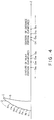
- Fig. 4 shows the centers O F1 , O F2 , ... of the curvatures of the distance portion curved surfaces F1, F2, ... and the centers O N1 , O N2 , ... of the curvatures of the near portion curved surfaces N1, N2, ... obtained as described above.
- Fig. 4 indicates that the centers O F1 , O F2 , ... of the curvatures of the distance portion curved surfaces F1, F2, ... are distributed in the z-axis direction so as to be shifted in sequence in the direction from the front curve 2 to the base curve 3.
- the centers O N1 , O N2 , ... of the curvatures of the near portion curved surfaces N1, N2, .. are distributed in the direction opposite to the z-axis direction so as to be shifted in sequence in the direction from the base curve 3 to the front curve 2.
- the conventional contact lens involves another problem in that in use of the contact lens, it is impossible to obtain a desired field of vision (as wide as a normal naked eye) and a natural peripheral field of vision.
- the lens since the lens is so designed and so manufactured that the optical energy incident upon the distance portions is equal to that incident upon the near portions, when the lens is used as the near portion lens (e.g., for reading or desk working), the light rays passed through the distance portions are not focused at the retina, and when used as the distance portion lens (e.g., for outdoor use), the light rays passed through the near portions are not focused at the retina.
- the function of the lens formed with both the distance portions and the near portions is reduced half in indoor use or in outdoor use, thus the conventional contact lens being not easy to use.
- the contact lens 1 provided with the front curve 2 formed with the distance portion curved surfaces and the near portion curved surfaces arranged alternately and repeatedly in concentric zone shape since the front curve 2 is formed with the distance and near portion curved surfaces with different radii of curvatures (not a single smoothly curved surface), there exists a problem in that it is impossible to polish the surface of the contact lens uniformly including the boundary portions between the adjoining distance and near portion curved surfaces.
- another object of the present invention is to provide a contact lens having a desired field of vision, for instance, as wide a field of vision as the normal naked eye and further natural in the peripheral field of vision and additionally clear in eyesight.
- Another object of the present invention is to provide a contact lens provided with the performance of almost a single focal lens but with the functions of both the distance portion lens and the near portion lens by using the lens properly according to indoor use and outdoor use.
- the other object of the present invention is to provide a method manufacturing a contact lens which can be polished uniformly including the boundary portions between the two adjoining distance portion curved surfaces and the near portion curved surfaces.
- the present invention provides a contact lens provided with a front curve formed with a plurality of distance portion curved surfaces for seeing a distant place and a plurality of near portion curved surfaces for seeing a near place arranged alternately and repeatedly in concentric zone shape, wherein the distance portion curved surfaces formed at least a central zone of the front curve have respective curvature centers positioned increasing distance away from an optical axis and the front curve of the contact lens respectively, as the distance portion curved surfaces are located increasing distance away from the optical axis, and further the curvature centers of the distance portion curved surfaces are so arranged that light rays parallel to the optical axis and allowed to be incident upon the distance portion curved surfaces are focused at roughly the same point on the optical axis; and the near portion curved surfaces formed at least the central zone of the front curve have respective curvature centers positioned increasing distance away from the optical axis and decreasing distance close to the front curve of the contact lens respectively, as the near portion curved surfaces are located increasing distance away from the
- the present invention provides a contact lens provided with a front curve formed with a plurality of distance portion curved surfaces for seeing a distant place and a plurality of near portion curved surfaces for seeing a near place arranged alternately and repeatedly in concentric zone shape, wherein the distance portion curved surfaces formed at a central zone of the front curve have respective curvature centers positioned increasing distances away from an optical axis and the front curve of the contact lens respectively, and the distance portion curved surfaces formed radially outside the central zone of the front curve have respective curvature centers positioned increasing distance away from the optical axis and decreasing distance close to the front curve of the contact lens respectively, as the distance portion curved surfaces are located increasing distance away from the optical axis, and further the curvature centers of the distance portion curved surfaces are so arranged that light rays parallel to the optical axis and allowed to be incident upon the distance portion curved surfaces are focused at roughly the same point on the optical axis; and the near portion curved surfaces formed at the central zone of the front curve have respective curvature
- respective radial zone widths of the distance portion curved surfaces change according to distance between the distance portion curved surface and an optical axis of the contact lens; and respective radial zone widths of the near portion curved surfaces change according to distance between the near portion curved surface and the optical axis of the contact lens.
- the respective radial zone widths of the distance portion curved surfaces increase with increasing distance between the distance portion curved surface and the optical axis of the contact lens; and respective radial zone widths of the near portion curved surface increase with increasing distance between the near portion curved surface and the optical axis of the contact lens.
- respective radial zone widths of the distance portion curved surfaces decrease with increasing distance between the distance portion curved surface and the optical axis of the contact lens; and respective radial zone widths of the near portion curved surface decrease with increasing distance between the near portion curved surface and the optical axis of the contact lens.
- respective radial zone widths of the distance portion curved surfaces decrease or increase with increasing distance between the distance portion curved surface and the optical axis of the contact lens; and respective radial zone widths of the near portion curved surface increase or decrease with increasing distance between the near portion curved surface and the optical axis of the contact lens.
- the present invention provides a contact lens provided with a front curve formed with a plurality of distance portion curved surfaces for seeing a distant place and a plurality of near portion curved surfaces for seeing a near place arranged alternately and repeatedly in concentric zone shape, wherein respective radial zone widths of the distance portion curved surfaces are roughly equal to each other; and respective radial zone widths of the near portion curved surfaces are roughly equal to each other.
- present invention provides a contact lens provided with a front curve formed with a plurality of distance portion curved surfaces for seeing a distant place and a plurality of near portion curved surfaces for seeing a near place arranged alternately and repeatedly in concentric zone shape, wherein energy ratio of the distance portion curved surfaces to the near portion curved surfaces is determined on the basis of a rate according to outdoor use and indoor use.
- the distance portion curved surfaces are tinted so as to function as a sun glass.
- the present invention provides a method of manufacturing a contact lens provided with a front curve formed with a plurality of distance portion curved surfaces for seeing a distant place and a plurality of near portion curved surfaces for seeing a near place arranged alternately and repeatedly in concentric zone shape, wherein a soft polishing cloth is brought into pressure contact with the front curve of the contact lens by hydraulic pressure, and the front curve and the polishing cloth are both moved relative to each other to polish the front curve.
- the distance portion curved surfaces formed at least a central zone of the front curve have respective curvature centers positioned increasing distance away from the optical axis and the front curve of the contact lens respectively, as the distance portion curved surfaces are located increasing distance away from the optical axis, and further since the curvature centers of the distance portion curved surfaces are so arranged that light rays parallel to the optical axis and allowed to be incident upon the distance portion curved surfaces are focused at roughly the same point on the optical axis, it is possible to remove the spherical aberration from the distance portion curved surfaces.
- the near portion curved surfaces formed at least a central zone of the front curve have respective curvature centers positioned increasing distance away from the optical axis and decreasing distance close to the front curve of the contact lens respectively, as the near portion curved surfaces are located increasing distance away from the optical axis, and further since the curvature centers of the near portion curved surfaces are so arranged that light rays parallel to the optical axis and allowed to be incident upon the near portion curved surfaces are focused at roughly the same point on the optical axis, it is possible to remove the spherical aberration from the near portion curved surfaces.
- the respective radial zone widths of the distance portion curved surfaces change according to distance between the distance portion curved surface and the optical axis of the contact lens; and further since the respective radial zone widths of the near portion curved surfaces change according to distance between the near portion curved surface and the optical axis of the contact lens, it is possible to obtain a desired field of vision roughly as wide a field as the normal naked eye, for instance and in addition to obtain a natural peripheral field of vision and a clear eyesight.
- the contact lens suitable for indoor use for book reading or desk work it is preferable to use the contact lens with a large energy ratio in the near portion curved surfaces, because a near object can be seen easily through the near portion curved surfaces and further a distant object can be seen through the distance portion curved surfaces.
- the contact lens suitable for outdoor use for sports or car driving it is preferable to use the contact lens with a large energy ratio in the distance portion curved surfaces, because a distant object can be seen easily through the distance portion curved surfaces and further a near object can be seen through the near portion curved surfaces.
- the distance portion curved surfaces are tinted, since ultraviolet rays can be cut off by the tinted distance portions, it is possible to provide a more clear eyesight through the near portions in indoor use.
- the contact lens 1 is provided with a front curve 2 and a base curve 3.
- the front curve 2 is formed with a plurality of distance portion curved surfaces F1, F2, ... and a plurality of near portion curved surfaces N1, N2 .... These distance and near portion curved surfaces are arranged alternately and repeatedly in concentric zone shape.
- the optical axis of the contact lens 1 is taken along a z axis extending from the front curve 2 to the base curve 3. Further, a vertical line passing through an apex P of the contact lens 1 is taken along an x axis perpendicular to the z axis.
- the curved surface shape of the base curve 3 is determined individually according to the curved surface of a user' cornea. On the basis of the value of the determined curved surface shape of the base curve 3, the radius r F of curvature of the distance portion curved surfaces F1, F2, ... is determined to obtain any desired power of the distance portions, and the radius r N of curvature of the near portion curved surfaces N1, N2, .... is determined to obtain an added power to the distance portions as the near portions.
- the curvature centers O F1 , O F2 , ... of the distance portion curved surfaces F1, F2, ... formed at least the central zone of the front curve 2 and the curvature centers O N1 , O N2 , ... of the near portion curved surfaces N1, N2, .. formed at least the central zone of the front curve 2 are determined as follows: First, as shown in Fig. 3, a position remote from the apex P by the curvature radius r F of the distance portions is taken on the optical axis as the curvature center O F1 of the distance portion curved surface F1.
- a circle with a radius r F is described with this curvature center O F1 as its center to obtain an intersection point P F1 between the described circle and a straight line l F1 parallel to the optical axis.
- This parallel straight line l F1 is used to determine a predetermined radial zone width of the distance portion curved surface F1.
- a circle with a radius r N is described with a point P F1 as its center to obtain an intersection point O N1 between the described circle and the optical axis, as the curvature center O N1 of the near portion curved surface N1, in the same way as with the case of the conventional contact lens as shown in Fig. 6.
- parallel light rays are allowed to be incident upon the distance portion curved surface F1, and an intersection point between the ray outgoing from the base curve 3 and the optical axis is defined as a distance portion focal point F F .
- parallel light rays are allowed to be incident upon the near portion curved surface F1, and an intersection point between the ray outgoing from the base curve 3 and the optical axis is defined as a near portion focal point F N .
- a curvature center O F2 of the distance portion curved surface F2 is obtained as follows: A circle with a radius r N is described with the curvature center O N1 as its center to obtain an intersection point P N1 between the described circle and a straight line l N1 parallel to the optical axis to determine a predetermined radial zone width of the near portion curved surface N1. Further, a circle with a radius r F is described with P N1 as its center to obtain an intersection point between the described circle and the optical axis as a candidate point of the center O F2 of the curvature of the near portion curved surface F2.
- the curvature center O F2 is obtained in accordance with the following ray tracing method: First, a circle with a radius r F is described with the candidate point of the curvature center O F2 as its center to obtain an intersection point P F2 between the described circle and a straight line l F2 . The shape of the distance portion curved surface F2 is determined between the point P N1 and the point P F2 .
- the distance portion curved surface F2 extending between the points P N1 and P F2 is rotated slightly counterclockwise in Fig. 3 with the point P N1 as its center. Parallel light rays in a range between the two straight lines l N1 and l F2 are allowed to be incident upon the distance portion curved surface F2 to obtain an intersection position between the light outgoing from the base curve 3 and optical axis.
- the distance portion curved surface F2 is further rotated counterclockwise with the point P N1 as its center.
- the distance portion curved surface F2 is rotated clockwise with the point P N1 as its center.
- the rotation position of the distance portion curved surface F2 about the point P N1 is determined in such a way that the parallel light rays allowed to be incident upon the front curve 2 are passed through the distance portion focal point F F .
- the curvature center of the distance portion curved surface F2 thus obtained becomes the curvature center O F2 required to be obtained.
- a circle with a radius r N is described with the point P F2 of the distance portion curved surface F2 determined as above as its center, to obtain an intersection point between the described circle and the optical axis as a first candidate point.
- a circle with a radius r N is described with this candidate point as its center to obtain an intersection point P N2 between the described circle and a straight line l N2 .
- the shape of the near portion curved surface N2 is determined between the point P F2 and the point P N2 .
- the near portion curved surface N2 extending between the points P F2 and P N2 is rotated slightly counterclockwise in Fig. 3 with the point P F1 as its center.
- Parallel light rays in a range between the two straight lines l F2 and l N2 are allowed to be incident upon the near portion curved surface N2 to obtain an intersection position between the light outgoing from the base curve 3 and optical axis.
- the near portion curved surface N2 is further rotated counterclockwise with the point P F2 as its center.
- the near portion curved surface N2 is rotated clockwise with the point P F2 as its center.
- the rotation position of the near portion curved surface N2 about the point P F2 is determined in such a way that the parallel light rays allowed to be incident upon the near portion curved surface N2 are passed through the near portion focal point F N .
- the curvature center of the near portion curved surface N2 thus obtained becomes the curvature center O N2 required to be obtained.
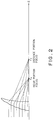
- Fig. 1 shows the curvature centers O F1 , O F2 , ... of the distance portions and the curvature centers O N1 , O N2 , ... of the near portions, respectively.
- Fig. 1 indicates that the curvature centers O F1 , O F2 , ... of the distance portions formed at least the central zone of the front curve are positioned increasing distance away from the optical axis and additionally away from the front curve 2, as the distance portion curved surfaces are located increasing distance away from the optical axis.
- Fig. 1 indicates that the curvature centers O N1 , O N2 , ... of the near portions formed at least the central zone of the front curve are positioned increasing distance away from the optical axis but decreasing distance close to the front curve 2, as the near portion curved surfaces are located increasing distance away from the optical axis.
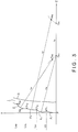
- Fig. 2 indicates that the parallel light rays incident upon the respective distance portion curved surfaces F1, F2, ... are focused at the distance portion focal point F F , and the parallel light rays incident upon the respective near portion curved surfaces N1, N2, ... are focused at the near portion focal point F N , without producing the spherical aberration.
- the respective distance portion curved surfaces F1, F2, ... and the respective near portion curved surfaces N1, N2, ... are both formed as plus (convex) lenses in relation to the base curve 3.
- the above-mentioned method can be applied to the cases where the distance portions are formed as minus (concave) lenses and the near portions are formed as plus (convex) lenses or where the distance and near portions are both formed as minus (concave) lenses.
- the inclination direction of the respective distance portion curved surfaces F2, F3, ... are rotated in the counterclockwise direction about the points P N1 , P N2 , ..., in comparison with the conventional contact lens as shown in Fig. 6.
- the respective distance portion curved surfaces F2, F3, ... are rotated in the clockwise direction about the points P N1 , P N2 .
- the inclination direction of the curved surfaces N2, N3, ... becomes opposite to that of the near portions of plus lenses.
- the distance portion curved surfaces formed outside the central zone of the front curve 2 it is possible to obtain the respective curvature centers in accordance with the ray tracing method, in such a way that the spherical aberration can be eliminated, in the same way as with the case of the distance portion curved surfaces F2, F3, ... formed at the central zone of the front curve 2.
- These curvature centers are positioned increasing distance away from the optical axis but decreasing distance close to the front curve 2, as the distance portion curved surfaces are located increasing distance away from the optical axis.
- the contact lens 1 used in this embodiment is a soft contact lens of moisture content type, whose base curve 3 is 8.6 mm in moisture content state. Further, the respective radial zone widths of the distance and near portions are 0.3 mm in non-moisture content state.
- the curvature of radius of the distance portions is 7.2489 mm and that of the near portions is 6. 9788 mm in non-moisture content state during the manufacturing process.
- the change in the curvature centers of the respective zones can be shown as listed in Tables 1 and 2 below.
- Table 1 indicates that the z coordinate of the distance portions increase monotonously from the first to fifth zones. Further, Table 2 indicates that the z coordinate of the near portions increase monotonously from the first to fourth zones, but begins to increase from the fourth to fifth zones. Accordingly, in the near portions, the first to fourth zones constitute the central zone of the front curve.
- the curvature of radius of the distance portions is 6.7549 mm and that of the near portions is 6.1966 mm in non-moisture content state during the manufacturing process.
- the zones are defined in sequence beginning from the center of the contact lens 1 in the radially outward direction as a first distance zone, a first near zone, a second distance zone, a second near zone, ...
- the change in the curvature centers of the respective zones can be shown as listed in Tables 3 and 4 below.
- Table 3 indicates that the z coordinate of the distance portions increase monotonously from the first to fifth zones. Further, Table 4 indicates that the z coordinate of the near portions increase monotonously from the first to third zones, but begins to increase from the third to fourth zones. Accordingly, in the near portions, the first to third zones constitute the central zone of the front curve.
- the curvature of radius of the distance portions is 7.8218 mm and that of the near portions is 7.5082 mm in non-moisture content state during the manufacturing process.
- the zones are defined in sequence beginning from the center of the contact lens 1 in the radially outward direction as a first distance zone, a first near zone, a second distance zone, a second near zone, ...
- the change in the curvature centers of the respective zones can be shown as listed in Tables 5 and 6 below.
- Table 5 indicates that the z coordinate of the distance portions increase monotonously from the first to fourth zones, and begins to decrease from the fourth to fifth zones. Accordingly, in the distance portions, the first to fourth zones constitute the central zone of the front curve. Further, Table 6 indicates that the z coordinate of the near portions increase monotonously from the first to fifth zones.
- the distance portion curved surfaces of at least the central zone of the front curve are so formed as to have the curvature centers positioned increasing distance away from the optical axis and further the front curve, as the distant portions curved surfaces are located increasing distance away from the optical axis.
- the near portion curved surfaces of at least the central zone of the front curve are so formed as to have the curvature centers positioned increasing distance away from the optical axis but decreasing distance close to the front curve, as the near portions curved surfaces are located increasing distance away from the optical axis. Accordingly, it is possible to eliminate the spherical aberration of the contact lens 1. As a result of this, it is possible to realize a contact lens formed with both distance and near portions through which more clear eyesight can be obtained, as compared with the conventional contact lens.
- the contact lens formed with the alternately arranged distance and near portion curved surfaces is described by way of example.
- the contact lens provided with the front curve formed with the distance and near portion curved surfaces arranged alternately and repeatedly in concentric zone shape by setting predetermined refractive indices to the respective concentric zones, without determining the geometrical shapes of the contact lens 1.
- the contact lens according to the present invention is further improved so as to be used in more comfortable way according to the environment in which the contact lens is used, under consideration that the diameter of pupils vary according to the environment where of the contact lenses are used. This is because when seeing an object, the diameter of the pupil changes according to a distance to the object or the quantity of light allowed to be incident upon the pupil (i.g., brightness).
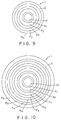
- the contact lens 1 has a front curve 2 formed with a plurality of distance portion curved surfaces F1, F2, ... and a plurality of near portion curved surfaces N1, N2, ... arranged alternately and repeatedly in concentric zone shape.
- each of the concentric zones of the respective distance portion curved surfaces F1, F2, ... increases with increasing distance away from the optical axis.
- the radial width of each of the concentric zones of the respective near portion curved surfaces N1, N2, ... also increases with increasing distance away from the optical axis.
- Table 7 lists practical numerical values, in which the radial widths of the respective concentric zones increase beginning from the radial width (i.e., a radius of the central circle) of the innermost central zone (distance portion curved surface F1) in the radial direction in geometrical progression manner at a determined change rate of radial width. In practice, it is preferable that the radial width in the innermost central zone lies within a range from 0. 1 mm to 0. 5 mm. Table 7 WIDTH IN CENTRAL ZONE CHANGE RATE IN ZONE WIDTH 0.1 mm 1.01 to 2.7 0.3 1.01 to 1.5 0.5 1.01 to 1.3
- the radial widths of the concentric zones of the respective distance portion curved surfaces F1, F2, ... and the near portion curved surfaces N1, N2, ... are determined by the intersection points P F1 , P N2 , P F2 , P N2 ... between the straight lines l F1 , l N1 , l F2 , l N2 , ... parallel to the z axis and the front curve 2, as shown in Fig. 3.
- the radial width of the distance portion curved surface F1 is a length between the apex point P on the curved surface and the intersection point P F1 .
- the radial width of the distance portion curved surface F2 is a length between the intersection point P F1 on the curved surface and the intersection point P N1 .
- the other radial widths can be defined in the same way. Further, since the respective radial widths are very narrow, it is possible to determine the radial width of the distance portion curved surface F2 (between the intersection points P F1 and P N1 in the curved surface) to be roughly equal to the length of the straight line between the apex point P and the intersection point P F1 or further the length between the straight lines l F1 and l N1 , for instance.
- the radial width is widened at the peripheral portion of the contact lens 1, it is possible to obtain a broader peripheral field of vision.
- the radial width of each of the concentric zones of the respective distance portion curved surfaces F1, F2, ... decreases with increasing distance from the optical axis.
- the radial width of each of the concentric zones of the respective near portion curved surfaces N1, N2, ... also decreases with increasing distance from the optical axis.
- Table 8 lists practical numerical values, in which the radial widths of the respective concentric zones decrease beginning from the radial width (i.e., a radius of the central circle) of the innermost central zone (distance portion curved surface F1) in the radial direction in geometrical progression manner at a given radial width change rate. In practice, it is preferable that the radial width in the innermost central zone lies within a range from 0. 2 mm to 1. 4 mm. Table 8 WIDTH IN CENTRAL ZONE CHANGE RATE IN ZONE WIDTH 0.2 mm 0.99 to 0.93 0.5 0.99 to 0.83 1.0 0.85 to 0.67
- the radial width is widened at the central zone of the contact lens 1, it is possible to obtain a field of more clear vision.
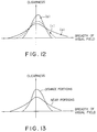
- Fig. 13 represents the conceptual relationship between the breadth of the field of vision and the clearness of the eyesight in comparison between the distance portions and the near portions.
- the contact lens in such a way that the radial width of each of the concentric zones of the respective distance portion curved surfaces F1, F2, ... increases with increasing distance from the optical axis, and the radial width of each of the concentric zones of the respective near portion curved surfaces N1, N2, ... decreases with increasing distance from the optical axis.
- the conceptual relationship between the breadth of the field of vision and the clearness of the eyesight of both the distance portions and the near portions becomes opposite to that as shown in Fig. 13.
- the diameter of the pupil changes according to the distance to the object and the brightness (i.e., the quantity of light incident upon the pupil). That is, when seeing a distant object outdoors, the pupil diameter increases; and when seeing a near object indoors, the pupil diameter decreases. Further, the pupil diameter becomes large in a dark place but small in a bright place.
- the circular zone of the curved surfaces available for the pupil lies in an area of the curved surfaces F1, N1, F2, N2, ... included in a circle described with a pupil center as its center. Therefore, when the pupil diameter changes, the circular zone of the curved surfaces also changes.
- the radial zone width of the distance portion curved surfaces F1, F2, ... and the radial zone width of the near portion curved surfaces N1, N2, ... change in the radial direction of the lens.
- the ratios F1 / N1, F2 / N2, ... of the radial zone width of the distance portion curved surfaces to the radial zone width of the near portion curved surfaces also change in the radial direction of the lens.
- the ratios decrease in the lens radial direction; and in the case of the contact lens shown in Fig. 10, the ratios increases in the lens radial direction. Accordingly, in the case where the contact lens as shown in Fig. 9 or 10 is used, whenever the pupil diameter changes, the ratio of the distance portions to the near portion contributing to the pupil changes. As already explained, since the pupil diameter changes according to the environment in which the contact lens is used, when the contact lens as shown in Figs.
- the contact lens 9 or 10 (the ratio of the radial zone width of the distance portion curved surfaces to that of the near portion curved surfaces changes in the lens radial direction) is used, it is possible to select the contact lens usable more comfortably according to the user' environments, for instance such as for indoor use or outdoor use.
- a fifth embodiment of the present invention will be described hereinbelow with reference to Fig. 11.
- the radial zone widths of the respective distance portion curved surfaces F1, F2, ... are roughly equal to each other, and further the radial zone widths of the respective near portion curved surfaces N1, N2, ... are roughly equal to each other.
- This fifth embodiment provides both the feature of the second embodiment such that the peripheral field of vision is wide and the feature of the third embodiment such that the clear eyesight can be obtained; that is, an intermediate characteristics between the two embodiments can be obtained.
- Fig. 12 shows the conceptual characteristics of the second embodiment (a), the third embodiment (b) and the fifth embodiment (c), respectively. Further, in the embodiments shown in Figs. 7 to 11, although only several distance portion curved surfaces F1, F2, ... and only several near portion curved surfaces N1, N2, ... are shown, about 5 to 30 curved surfaces are formed in practice, respectively.
- the second to fifth embodiments relate to only the relationship between the respective radial widths of the respective distance portion curved surfaces F1, F2, .... or only the relationship between the respective radial widths of the respective near portion curved surfaces N1, N2, .
- the relationship between the radial zone widths of the respective distance portion curved surfaces F1, F2, ... and the radial zone widths of the respective near portion curved surfaces N1, N2, ... are not defined. In other words, there exists no problem even if the radial widths of both the distance and near portions are equal to each other or not equal to each other.
- the brightness can be made roughly equal to each other between the distance and near portions.
- the innermost zone is formed by the distance portion curved surface F1.
- the innermost zone is formed by the near portion curved surface N1.
- the contact lens 1 is formed with a front curve 2 and a base curve 3 fitted to a curved surface of the user' cornea.
- the front curve 2 is formed with a plurality of distance portion curved surfaces F1, F2, ... and a plurality of near portion curved surfaces N1, N2, .... These distance and near portion curved surfaces are arranged alternately and repeatedly in concentric zone shape.
- the ratio of energy transmitted through the distance portion curved surfaces F1, F2, ... to the energy transmitted through the near portion curved surfaces N1, N2, .... is determined to be different on the basis of the lens specifications, for instance such as for indoor use or outdoor use.
- This energy ration can be determined on the basis of the ratio of the total area of the distance portion curved surfaces F1, F2, ... to the total area of the near portion curved surfaces N1, N2 ...., for instance.
- the ratio of the total area of the distance portion curved surfaces F1, F2, ... to the total area of the near portion curved surfaces N1, N2, ... lies within a range from 7 : 3 to 8: 2.
- the same ratio lies within a range reciprocal to the above. Further, it is possible to obtain the above-mentioned energy ratio on the basis of the ratio of the quantity of light transmitted through the respective distance and near portions, without depending upon the ratio in area.
- the contact lens suitable for the indoor use for book reading or desk work it is preferable to use the contact lens 10 N with a large energy ratio in the near portion curved surfaces N1, N2, ..., because a near object can be seen easily through the near portion curved surfaces and further a distant object can be seen through the distance portion curved surfaces.
- the contact lens suitable for the outdoor use for sports watching or car driving it is preferable to use the contact lens 10 F with a large energy ratio in the distance portion curved surfaces N1, N2, ..., because a distant object can be seen easily through the distance portion curved surfaces and further a near object can be seen through the near portion curved surfaces.
- the distance portion curved surfaces F1, F2, .. are tinted, since ultraviolet rays can be cut off by the tinted distance portions, it is possible to provide a more clear eyesight through the near portions in indoor use.
- a contact lens provided with the performance nearly equivalent to a single vision lens and additionally the functions of both the distance and near portions when the contact lens is used properly according to the user' purpose such as indoor use, outdoor use, etc.; that is, according to various purposes. Further, when the spherical aberration is removed, it is possible to realize a contact lens further easy to see. Further, when the distance portions are colored, it is possible to provide a contact lens which functions as a sun glass in outdoor use and provides a more clear eyesight in indoor use by cutting off light coming from distant positions.
- the method of manufacturing a contact lens with the use of a soft polishing cloth is disclosed in Japanese Published Unexamined (Kokai) Patent Application No. 2-83153.
- the method of manufacturing the contact lens as disclosed in the above-mentioned document is applied to the contact lens 1 provided with a front curve 2 formed with a plurality of distance portion curved surfaces and a plurality of near portion curved surfaces arranged alternately and repeatedly in concentric zone shape.
- a soft polishing cloth is attached onto a rotatable table 11.
- the rotatable table 11 can rotate about a central axle 12 of the rotating polishing cloth, and the polishing cloth 10 rotates together with the rotatable table 11.
- a nozzle 13 is disposed below the rotatable table 11 in such a way that the upper portion of the nozzle 13 is covered with a part of the polishing cloth 10.
- a fixture tool 14 is disposed over the nozzle 13. This tool 14 rotates about a central axle 15 of the rotating fixture tool 14.
- a contact lens 1 to be polished is supported on the bottom surface of the fixture tool 14 with a bonding agent attached to the base curve 3.
- a compressed air 18 is allowed to flow from below to above within the nozzle 13, so that the polishing cloth 10 covering the nozzle 13 is blown in the upward direction by the hydraulic pressure of the compressed air flowing through the nozzle 13. Accordingly, the polishing cloth 10 is brought into pressure contact with the front curve 2 of the contact lens 1.
- An abrasive powder of Al2O3 dispersed in water or oil is supplied between the front curve 2 and the polishing cloth 10.
- a polishing cloth now on the market such as a polishing cloth lined with polyurethane can be used, for instance.
- the inner diameter of the nozzle 13 is determined to be larger than the outer diameter of the front curve 2, and the hydraulic pressure is kept at a constant value at the peripheral portion of the front curve 2 so that a uniform contact pressure can be obtained all over the front curve 2.
- the manufacturing process of the contact lens 1 other than the above-mentioned polishing process is almost the same as the conventional process.
- a soft polishing cloth 10 is brought into pressure contact with the front curve 2 by pressure of air 18 and further the front curve 2 is moved relative to the polishing cloth 10 in order to polish the front curve 2. Therefore, since the polishing cloth 10 is allowed to follow softly the curved surfaces of the front curve 2, it is possible to polish the contact lens 1 uniformly including the adjoining portions between the distance portion curved surfaces F1, F2, ... and the near portion curved surfaces N1, N2, ...
- a molding die for molding the contact lens of the present invention will be described hereinbelow with reference to Figs. 18 to 20.
- a contact lens molding die 20 is formed with a front curve molding die surface 22 corresponding to the front curve 2 of the contact lens 1. That is, the front curve molding die surface 22 is formed with distance portion die curved surfaces F1', F2', ... and the near portion die curved surfaces N1', N2', ... corresponding to the convex and concave relationship with respect to the distance portion curved surfaces F1, F2, ... and the near portion curved surfaces N1, N2, ..., respectively.
- the distance portion die curved surfaces F1', F2', ... and the near portion die curved surfaces N1', N2', ... are determined in accordance with the ray tracing method in the same way as in the first embodiment.
- the shapes of the distance portion curved surfaces F1, F2, ... and the near portion curved surfaces N1, N2, ... of the contact lens 1 are first obtained in accordance with the ray tracing method, and then the die curved surfaces related to these curved surfaces are determined.
- a raw lens material 24 is placed on the front curve molding die surface 22 formed with distance portion die curved surfaces F1', F2', ... and the near portion die curved surfaces N1', N2', ...
- a base curve molding die 25 formed with a base curve molding die surface 23 corresponding to the convex and concave relationship with respect to the base curve 3 is joined with the front curve molding die 20 at a predetermined positional relationship between the base curve molding die surface 23 and the front curve molding die surface 22.
- both the molding dies 20 and 22 are heated by ultraviolet rays or heat to polymerize the lens material 24. Further, the space between the front curve molding die surface 22 and the base curve molding die surface 23 is so determined as to form a desired contact lens.
- a raw lens material 24 is placed on the front curve molding die surface 22 formed with distance portion die curved surfaces F1', F2', ... and the near portion die curved surfaces N1', N2', ... Thereafter, as shown in Fig. 20(B), the contact lens molding die 20 is rotated.
- the base curve 2 is formed by controlling the rotational speed of the contact lens molding die 20. Further, it is also possible to form the base curve by cutting the contact lens with a lathe, for instance.
- the front curve molding die surface 22 of the contact lens molding die 20 is formed with distance portion die curved surfaces F1', F2', ... and the near portion die curved surfaces N1', N2', ... corresponding to the convex and concave relationship with respect to the distance portion curved surfaces F1, F2, ... and the near portion curved surfaces N1, N2, ..., respectively, it is possible to manufacture the contact lens formed with the distance portions and the near portions from which spherical aberration can removed with the use of the contact lens molding die 20.
Abstract
Applications Claiming Priority (5)
| Application Number | Priority Date | Filing Date | Title |
|---|---|---|---|
| JP39992 | 1992-01-06 | ||
| JP399/92 | 1992-01-06 | ||
| JP10974392 | 1992-04-28 | ||
| JP109743/92 | 1992-04-28 | ||
| PCT/JP1992/001730 WO1993014434A1 (fr) | 1992-01-06 | 1992-12-28 | Lentille de contact |
Publications (3)
| Publication Number | Publication Date |
|---|---|
| EP0574590A1 true EP0574590A1 (fr) | 1993-12-22 |
| EP0574590A4 EP0574590A4 (fr) | 1994-04-06 |
| EP0574590B1 EP0574590B1 (fr) | 1998-07-08 |
Family
ID=26333379
Family Applications (1)
| Application Number | Title | Priority Date | Filing Date |
|---|---|---|---|
| EP93900410A Expired - Lifetime EP0574590B1 (fr) | 1992-01-06 | 1992-12-28 | Lentille de contact |
Country Status (5)
| Country | Link |
|---|---|
| US (1) | US5541678A (fr) |
| EP (1) | EP0574590B1 (fr) |
| JP (1) | JP3286977B2 (fr) |
| DE (1) | DE69226172T2 (fr) |
| WO (1) | WO1993014434A1 (fr) |
Cited By (10)
| Publication number | Priority date | Publication date | Assignee | Title |
|---|---|---|---|---|
| EP0622653A1 (fr) * | 1993-04-26 | 1994-11-02 | Ciba-Geigy Ag | Lentille de contact multifocale |
| GB2295686A (en) * | 1994-11-30 | 1996-06-05 | Carle John Trevor De | Bifocal contact lens with aspherical near vision zone |
| EP0741315A2 (fr) * | 1995-05-04 | 1996-11-06 | JOHNSON & JOHNSON VISION PRODUCTS, INC. | Lentilles à des anneaux concentriques avec des angles entre des segments annulaires adjacentes minimalisés |
| EP0756189A2 (fr) * | 1995-05-04 | 1997-01-29 | JOHNSON & JOHNSON VISION PRODUCTS, INC. | Lentilles multifocales à pouvoir moyenne |
| EP0822439A1 (fr) * | 1996-02-21 | 1998-02-04 | Seiko Epson Corporation | Verres de contact a foyer progressif |
| EP1200869A1 (fr) * | 1999-07-19 | 2002-05-02 | Johson & Johnson Vision Care Inc. | Lentilles ophtalmiques multifocales et leurs procedes de production |
| EP1446692A1 (fr) * | 2001-08-14 | 2004-08-18 | Johson & Johnson Vision Care Inc. | Methodes de conception de lentilles ophtalmiques a foyers multiples |
| US6808262B2 (en) | 1998-12-16 | 2004-10-26 | Novartis Ag | Multifocal contact lens with aspheric surface |
| WO2011107723A1 (fr) * | 2010-03-05 | 2011-09-09 | John Trevor De Carle | Verre multifocal |
| EP2781952A1 (fr) * | 2013-03-22 | 2014-09-24 | Hecht Contactlinsen GmbH | Lentille ophtalmologique multifocale |
Families Citing this family (19)
| Publication number | Priority date | Publication date | Assignee | Title |
|---|---|---|---|---|
| US5702735A (en) * | 1994-06-10 | 1997-12-30 | Johnson & Johnson Vision Products, Inc. | Molding arrangement to achieve short mold cycle time |
| KR100234257B1 (ko) * | 1995-08-30 | 1999-12-15 | 윤종용 | 대물렌즈 장치 및 안정된 포커스 서보 신호를 얻는방법 및 이를 적용한 광픽업 장치 및 두께가 다른 디스크를 판별하는 방법 및 두께가 다른 디스크로부터 정보를 재생하고 기록하는 방법 |
| US5980040A (en) * | 1997-06-30 | 1999-11-09 | Wesley Jessen Corporation | Pinhole lens and contact lens |
| US6116735A (en) * | 1997-07-14 | 2000-09-12 | Seiko Epson Corporation | Contact lens |
| EP1103014A4 (fr) | 1998-08-06 | 2006-09-06 | John B W Lett | Lentilles multifocales aspheriques |
| US6210005B1 (en) | 1999-02-04 | 2001-04-03 | Valdemar Portney | Multifocal ophthalmic lens with reduced halo size |
| US6179420B1 (en) * | 1999-04-21 | 2001-01-30 | Johnson & Johnson Vision Products, Inc. | Multifocal ophthalmic lenses |
| WO2006018879A1 (fr) * | 2004-08-19 | 2006-02-23 | Menicon Co., Ltd. | Lentille de contact colorée multifocus et sa méthode de fabrication |
| DE102005043418A1 (de) * | 2005-09-13 | 2007-03-22 | Robert Bosch Gmbh | Elektro-optisches Messgerät |
| JP5313699B2 (ja) * | 2006-03-08 | 2013-10-09 | サイエンティフィック オプティクス, インク. | 視力の普遍的改善のための方法及び装置 |
| US7364291B2 (en) * | 2006-06-29 | 2008-04-29 | Johnson & Johnson Vision Care, Inc. | Contact lenses with light blocking rings |
| WO2008131479A1 (fr) * | 2007-04-27 | 2008-11-06 | The Institute For Eye Research Limited | Détermination d'ajustements optiques pour retarder la progression de la myopie |
| US7753521B2 (en) * | 2008-03-31 | 2010-07-13 | Johnson & Johnson Vision Care, Inc. | Lenses for the correction of presbyopia and methods of designing the lenses |
| BRPI1014443A2 (pt) * | 2009-05-04 | 2016-04-05 | Coopervision Int Holding Co Lp | lente oftálmica e redução de erro acomodatício |
| AU2010246171B2 (en) | 2009-05-04 | 2014-02-13 | Coopervision International Limited | Use of accommodative error measurements in providing ophthalmic lenses |
| CN102460276A (zh) * | 2009-05-04 | 2012-05-16 | 库柏维景国际控股公司 | 小视带接触镜片和方法 |
| AU2010308489C1 (en) | 2009-10-22 | 2015-07-02 | Coopervision International Limited | Contact lens sets and methods to prevent or slow progression of myopia or hyperopia |
| TWI526731B (zh) * | 2010-03-03 | 2016-03-21 | 布萊恩霍頓視力協會 | 用於近視眼的隱形眼鏡以及治療近視的方法 |
| US20230229020A1 (en) * | 2022-01-19 | 2023-07-20 | Coopervision International Limited | Contact lenses and methods relating thereto |
Citations (7)
| Publication number | Priority date | Publication date | Assignee | Title |
|---|---|---|---|---|
| US4162122A (en) * | 1977-09-14 | 1979-07-24 | Cohen Allen L | Zonal bifocal contact lens |
| DE3246306A1 (de) * | 1982-12-14 | 1984-06-14 | Titmus Eurocon Kontaktlinsen Gmbh & Co Kg, 8750 Aschaffenburg | Bifokallinse vom bivisuellen typ |
| EP0225098A2 (fr) * | 1985-11-19 | 1987-06-10 | University Optical Products Co | Lentille bifocale |
| WO1988009950A1 (fr) * | 1987-06-01 | 1988-12-15 | Valdemar Portney | Lentille ophtalmique multifocale |
| EP0367513A2 (fr) * | 1988-11-02 | 1990-05-09 | Btg International Limited | Coulage de lentilles de contact |
| EP0445994A2 (fr) * | 1990-03-08 | 1991-09-11 | Joseph Lawrence Breger | Lentilles multifocales à vision simultanée |
| US5106180A (en) * | 1991-05-30 | 1992-04-21 | Robert Marie | Multifocal ophthalmic lens |
Family Cites Families (7)
| Publication number | Priority date | Publication date | Assignee | Title |
|---|---|---|---|---|
| EP0107444B1 (fr) * | 1982-10-13 | 1990-06-27 | N.G. Trustees And Nominees Limited | Lentilles de contact bifocaux |
| US4890913A (en) * | 1982-10-13 | 1990-01-02 | Carle John T De | Zoned multi-focal contact lens |
| WO1984004724A1 (fr) * | 1983-05-26 | 1984-12-06 | Int Hydron Corp | Verre de contact hydrophile a trois rayons de courbure et son procede de moulage |
| US4898461A (en) * | 1987-06-01 | 1990-02-06 | Valdemar Portney | Multifocal ophthalmic lens |
| JPH0279015A (ja) * | 1988-09-14 | 1990-03-19 | Seiko Epson Corp | バイフォーカルコンタクトレンズ |
| JP2814495B2 (ja) * | 1988-09-16 | 1998-10-22 | セイコーエプソン株式会社 | コンタクトレンズの製造方法及び製造装置 |
| JPH02217818A (ja) * | 1989-02-20 | 1990-08-30 | Nippon Contact Lens Kk | 老視用コンタクトレンズ |
-
1992
- 1992-12-28 EP EP93900410A patent/EP0574590B1/fr not_active Expired - Lifetime
- 1992-12-28 WO PCT/JP1992/001730 patent/WO1993014434A1/fr active IP Right Grant
- 1992-12-28 JP JP50801993A patent/JP3286977B2/ja not_active Expired - Fee Related
- 1992-12-28 DE DE69226172T patent/DE69226172T2/de not_active Expired - Fee Related
-
1993
- 1993-12-03 US US08/108,689 patent/US5541678A/en not_active Expired - Fee Related
Patent Citations (7)
| Publication number | Priority date | Publication date | Assignee | Title |
|---|---|---|---|---|
| US4162122A (en) * | 1977-09-14 | 1979-07-24 | Cohen Allen L | Zonal bifocal contact lens |
| DE3246306A1 (de) * | 1982-12-14 | 1984-06-14 | Titmus Eurocon Kontaktlinsen Gmbh & Co Kg, 8750 Aschaffenburg | Bifokallinse vom bivisuellen typ |
| EP0225098A2 (fr) * | 1985-11-19 | 1987-06-10 | University Optical Products Co | Lentille bifocale |
| WO1988009950A1 (fr) * | 1987-06-01 | 1988-12-15 | Valdemar Portney | Lentille ophtalmique multifocale |
| EP0367513A2 (fr) * | 1988-11-02 | 1990-05-09 | Btg International Limited | Coulage de lentilles de contact |
| EP0445994A2 (fr) * | 1990-03-08 | 1991-09-11 | Joseph Lawrence Breger | Lentilles multifocales à vision simultanée |
| US5106180A (en) * | 1991-05-30 | 1992-04-21 | Robert Marie | Multifocal ophthalmic lens |
Non-Patent Citations (1)
| Title |
|---|
| See also references of WO9314434A1 * |
Cited By (16)
| Publication number | Priority date | Publication date | Assignee | Title |
|---|---|---|---|---|
| EP0622653A1 (fr) * | 1993-04-26 | 1994-11-02 | Ciba-Geigy Ag | Lentille de contact multifocale |
| AU682337B2 (en) * | 1993-04-26 | 1997-10-02 | Novartis Ag | Multifocal contact lens |
| GB2295686B (en) * | 1994-11-30 | 1998-05-06 | Carle John Trevor De | Bifocal contact lenses |
| GB2295686A (en) * | 1994-11-30 | 1996-06-05 | Carle John Trevor De | Bifocal contact lens with aspherical near vision zone |
| US5798817A (en) * | 1994-11-30 | 1998-08-25 | Aspect Vision Care Ltd. | Bifocal contact lenses |
| EP0741315A3 (fr) * | 1995-05-04 | 1998-10-28 | JOHNSON & JOHNSON VISION PRODUCTS, INC. | Lentilles à des anneaux concentriques avec des angles entre des segments annulaires adjacentes minimalisés |
| EP0756189A2 (fr) * | 1995-05-04 | 1997-01-29 | JOHNSON & JOHNSON VISION PRODUCTS, INC. | Lentilles multifocales à pouvoir moyenne |
| EP0741315A2 (fr) * | 1995-05-04 | 1996-11-06 | JOHNSON & JOHNSON VISION PRODUCTS, INC. | Lentilles à des anneaux concentriques avec des angles entre des segments annulaires adjacentes minimalisés |
| EP0756189B1 (fr) * | 1995-05-04 | 2006-07-05 | Johnson & Johnson Vision Care, Inc. | Lentilles multifocales à pouissance intermédiaire |
| EP0822439A1 (fr) * | 1996-02-21 | 1998-02-04 | Seiko Epson Corporation | Verres de contact a foyer progressif |
| EP0822439A4 (fr) * | 1996-02-21 | 2007-01-31 | Seiko Epson Corp | Verres de contact a foyer progressif |
| US6808262B2 (en) | 1998-12-16 | 2004-10-26 | Novartis Ag | Multifocal contact lens with aspheric surface |
| EP1200869A1 (fr) * | 1999-07-19 | 2002-05-02 | Johson & Johnson Vision Care Inc. | Lentilles ophtalmiques multifocales et leurs procedes de production |
| EP1446692A1 (fr) * | 2001-08-14 | 2004-08-18 | Johson & Johnson Vision Care Inc. | Methodes de conception de lentilles ophtalmiques a foyers multiples |
| WO2011107723A1 (fr) * | 2010-03-05 | 2011-09-09 | John Trevor De Carle | Verre multifocal |
| EP2781952A1 (fr) * | 2013-03-22 | 2014-09-24 | Hecht Contactlinsen GmbH | Lentille ophtalmologique multifocale |
Also Published As
| Publication number | Publication date |
|---|---|
| WO1993014434A1 (fr) | 1993-07-22 |
| DE69226172T2 (de) | 1998-12-17 |
| JP3286977B2 (ja) | 2002-05-27 |
| US5541678A (en) | 1996-07-30 |
| EP0574590B1 (fr) | 1998-07-08 |
| DE69226172D1 (de) | 1998-08-13 |
| EP0574590A4 (fr) | 1994-04-06 |
Similar Documents
| Publication | Publication Date | Title |
|---|---|---|
| EP0574590B1 (fr) | Lentille de contact | |
| US6086203A (en) | Progressive addition lenses | |
| US4693572A (en) | Monocentric bifocal corneal contact lens | |
| US5106180A (en) | Multifocal ophthalmic lens | |
| US6764180B2 (en) | Multifocal contact lens and method of making the same | |
| CN1030480C (zh) | 分段式多焦接触镜片 | |
| US5305028A (en) | Multifocal lens provided with progressive focal segment | |
| US5125729A (en) | Multifocal contact lens | |
| US4861152A (en) | Contact lens having at least one aspherical, progressive multifocal face, process for the preparation thereof and use of this contact lens as an intra-ocular implant to be substituted for the eye crystalline lens | |
| US7025455B2 (en) | Multifocal contact lenses having a pinhole | |
| US2405989A (en) | Lens | |
| US4971432A (en) | Bifocal contact lens | |
| US6176579B1 (en) | Bifocal contact lens with toric transition | |
| US8950858B2 (en) | System and method of surfacing a lens, such as a lens for use with eyeglasses | |
| EP0417136A1 (fr) | Lentille de contact multifocale a excentricite progressive. | |
| IE84161B1 (en) | Segmented multifocal contact lens | |
| US6874887B2 (en) | Multifocal contact lens | |
| US6007201A (en) | Multifocal contact lens | |
| EP0414890B1 (fr) | Lentille multifocale pourvue d'un segment de puissance progressive | |
| US20010028434A1 (en) | Bifocal contact lens | |
| GB2132785A (en) | Thin aphakic contact lens | |
| MXPA99008103A (en) | Addiction lenses progress |
Legal Events
| Date | Code | Title | Description |
|---|---|---|---|
| PUAI | Public reference made under article 153(3) epc to a published international application that has entered the european phase |
Free format text: ORIGINAL CODE: 0009012 |
|
| 17P | Request for examination filed |
Effective date: 19930910 |
|
| AK | Designated contracting states |
Kind code of ref document: A1 Designated state(s): DE FR GB |
|
| A4 | Supplementary search report drawn up and despatched |
Effective date: 19940217 |
|
| AK | Designated contracting states |
Kind code of ref document: A4 Designated state(s): DE FR GB |
|
| 17Q | First examination report despatched |
Effective date: 19951030 |
|
| GRAG | Despatch of communication of intention to grant |
Free format text: ORIGINAL CODE: EPIDOS AGRA |
|
| GRAG | Despatch of communication of intention to grant |
Free format text: ORIGINAL CODE: EPIDOS AGRA |
|
| GRAH | Despatch of communication of intention to grant a patent |
Free format text: ORIGINAL CODE: EPIDOS IGRA |
|
| GRAH | Despatch of communication of intention to grant a patent |
Free format text: ORIGINAL CODE: EPIDOS IGRA |
|
| GRAA | (expected) grant |
Free format text: ORIGINAL CODE: 0009210 |
|
| AK | Designated contracting states |
Kind code of ref document: B1 Designated state(s): DE FR GB |
|
| REF | Corresponds to: |
Ref document number: 69226172 Country of ref document: DE Date of ref document: 19980813 |
|
| ET | Fr: translation filed | ||
| PLBE | No opposition filed within time limit |
Free format text: ORIGINAL CODE: 0009261 |
|
| STAA | Information on the status of an ep patent application or granted ep patent |
Free format text: STATUS: NO OPPOSITION FILED WITHIN TIME LIMIT |
|
| 26N | No opposition filed | ||
| REG | Reference to a national code |
Ref country code: GB Ref legal event code: IF02 |
|
| PGFP | Annual fee paid to national office [announced via postgrant information from national office to epo] |
Ref country code: FR Payment date: 20061208 Year of fee payment: 15 |
|
| PGFP | Annual fee paid to national office [announced via postgrant information from national office to epo] |
Ref country code: DE Payment date: 20061221 Year of fee payment: 15 |
|
| PGFP | Annual fee paid to national office [announced via postgrant information from national office to epo] |
Ref country code: GB Payment date: 20061227 Year of fee payment: 15 |
|
| GBPC | Gb: european patent ceased through non-payment of renewal fee |
Effective date: 20071228 |
|
| PG25 | Lapsed in a contracting state [announced via postgrant information from national office to epo] |
Ref country code: DE Free format text: LAPSE BECAUSE OF NON-PAYMENT OF DUE FEES Effective date: 20080701 |
|
| REG | Reference to a national code |
Ref country code: FR Ref legal event code: ST Effective date: 20081020 |
|
| PG25 | Lapsed in a contracting state [announced via postgrant information from national office to epo] |
Ref country code: GB Free format text: LAPSE BECAUSE OF NON-PAYMENT OF DUE FEES Effective date: 20071228 |
|
| PG25 | Lapsed in a contracting state [announced via postgrant information from national office to epo] |
Ref country code: FR Free format text: LAPSE BECAUSE OF NON-PAYMENT OF DUE FEES Effective date: 20071231 |