EP0574550B1 - Stützfeder für Axiallager - Google Patents
Stützfeder für Axiallager Download PDFInfo
- Publication number
- EP0574550B1 EP0574550B1 EP92912139A EP92912139A EP0574550B1 EP 0574550 B1 EP0574550 B1 EP 0574550B1 EP 92912139 A EP92912139 A EP 92912139A EP 92912139 A EP92912139 A EP 92912139A EP 0574550 B1 EP0574550 B1 EP 0574550B1
- Authority
- EP
- European Patent Office
- Prior art keywords
- spring
- underspring
- radially
- bearing
- thrust
- Prior art date
- Legal status (The legal status is an assumption and is not a legal conclusion. Google has not performed a legal analysis and makes no representation as to the accuracy of the status listed.)
- Expired - Lifetime
Links
- 239000011888 foil Substances 0.000 claims abstract description 34
- 239000012530 fluid Substances 0.000 claims description 21
- 238000000034 method Methods 0.000 description 2
- 230000036316 preload Effects 0.000 description 2
- 239000003351 stiffener Substances 0.000 description 2
- 238000003486 chemical etching Methods 0.000 description 1
- 230000007423 decrease Effects 0.000 description 1
- 230000003247 decreasing effect Effects 0.000 description 1
- 230000001419 dependent effect Effects 0.000 description 1
- 230000000694 effects Effects 0.000 description 1
- 239000000463 material Substances 0.000 description 1
- 238000003466 welding Methods 0.000 description 1
Images

Classifications
-
- F—MECHANICAL ENGINEERING; LIGHTING; HEATING; WEAPONS; BLASTING
- F16—ENGINEERING ELEMENTS AND UNITS; GENERAL MEASURES FOR PRODUCING AND MAINTAINING EFFECTIVE FUNCTIONING OF MACHINES OR INSTALLATIONS; THERMAL INSULATION IN GENERAL
- F16C—SHAFTS; FLEXIBLE SHAFTS; ELEMENTS OR CRANKSHAFT MECHANISMS; ROTARY BODIES OTHER THAN GEARING ELEMENTS; BEARINGS
- F16C17/00—Sliding-contact bearings for exclusively rotary movement
- F16C17/04—Sliding-contact bearings for exclusively rotary movement for axial load only
- F16C17/042—Sliding-contact bearings for exclusively rotary movement for axial load only with flexible leaves to create hydrodynamic wedge, e.g. axial foil bearings
-
- F—MECHANICAL ENGINEERING; LIGHTING; HEATING; WEAPONS; BLASTING
- F16—ENGINEERING ELEMENTS AND UNITS; GENERAL MEASURES FOR PRODUCING AND MAINTAINING EFFECTIVE FUNCTIONING OF MACHINES OR INSTALLATIONS; THERMAL INSULATION IN GENERAL
- F16C—SHAFTS; FLEXIBLE SHAFTS; ELEMENTS OR CRANKSHAFT MECHANISMS; ROTARY BODIES OTHER THAN GEARING ELEMENTS; BEARINGS
- F16C27/00—Elastic or yielding bearings or bearing supports, for exclusively rotary movement
- F16C27/08—Elastic or yielding bearings or bearing supports, for exclusively rotary movement primarily for axial load, e.g. for vertically-arranged shafts
Definitions
- Fluid bearings are now being utilized in an increasing number of diverse applications. These fluid bearings generally comprise two relatively movable elements with a predetermined spacing therebetween filled with a fluid such as air, which, under dynamic conditions, form a supporting wedge sufficient to prevent contact between the two relatively movable elements.
- a fluid such as air
- Improved fluid bearings particularly gas bearings of the hydrodynamic type, have been developed by providing foils in the space between the relatively movable bearing elements.
- Such foils which are generally thin sheets of a compliant material, are deflected by the hydrodynamic film forces between adjacent bearing surfaces.
- the foils enhance the hydrodynamic characteristics of the fluid bearings and also provide improved operation under extreme load conditions when normal bearing failure might otherwise occur. Additionally, these foils provide the added advantage of accommodating eccentricity of the relatively movable elements and further provide a cushioning and dampening effect.
- the foil thrust bearing is provided with a thrust bearing underspring disk having a radially increasing spring force or load capacity.
- a plurality of spring sections formed in the underspring disk provide improved load capacity and pressure force distribution, allowing a maximum thrust load in excess of 5.516 x 10⁵ N/m2 (80 psi)to be attained.
- the present underspring disk includes sets of three spring elements spaced apart radially, with the outer spring element having a greater spring force resilience than the radially inner spring elements.
- the spring elements each include a plurality of corrugations, and the peak to peak length of the corrugations is shorter for the radially outer spring element than for the radially inner spring elements sections.
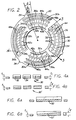
- Fig. 2 depicts an enlarged partial top plan view of the underspring 20 of Fig. 1.
- the underspring 20 includes means for radially increasing the spring force support of the overlying compliant foil 18 (of Fig. 1).
- the means for radially increasing the spring force of the underspring 20 of Fig. 2 preferably comprises a plurality of spring sections 30, each spring sections 30 including at least two and preferably three individual spring elements 32, 34, and 36 (numbered successively with increasing radius). It should be noted that four or more spring elements may be appropriate and indeed preferred for large diameter thrust bearings, however, for clarity only, three spring elements will be depicted and discussed.
- the three spring elements 32, 34, 36 are preferably individually corrugated 42, 44, 46, and configured to support a single overlying foil 18 of the bearing disk 16 (Fig. 1). Accordingly, the spring elements are arranged radially adjacent one another, extending through equal arc angles and thus traversing radially increasing arc lengths.
- the three spring elements 32, 34, 36 are depicted in a stacked, cross sectional view in Fig. 3, wherein the corrugations 42, 44, 46 of each spring element 32, 34, 36 respectively, is apparent. Further, the peak to peak length or pitch (P32, P34, P36) of the corrugations 42, 44, 46 of each spring element 32, 34, 36 is depicted. In order to provide increasing spring force at the radially outer spring elements 34, and 36, the pitch decreases, i.e. P32 is greater than P34 which in turn is greater than P36.
- the underspring 20 of Fig. 2 includes four alternative corrugation arrangements for the four spring sections 30, 30a, 30b, and 30c.
- the corrugations 42, 44, 46 are all radially aligned, thus the pitch of each individual spring element 32, 34, 36 also increases across the radial width of the respective element.
- the spring section 30a includes radially uniform, constant pitch corrugations 42a, 44a, 46a.
- all of the successive corrugations 42a, 44a, 46a align in parallel with the first corrugation 42a, 44a, 46a, which is proximate the leading edge.
- the first corrugation 42a, 44a, 46a is radially aligned.
- a third possible configuration is depicted in spring section 30b, wherein all of the corrugations 42b, 44b, 46b are set at an angle ⁇ with respect to a radius. It should be noted that the angle ⁇ is not necessarily the same for the respective spring elements 32b, 34b, 36b.
- a fourth possible configuration is depicted in spring section 30c, wherein all of the corrugations 42c, 44c, 46c are aligned in parallel with the last corrugation 42c, 44c, 46c, which is proximate the trailing edge of the spring elements 32c, 34c, 36c. Preferably, this last corrugation 42c, 44c, 46c is radially aligned.
- Figs 4A and 4B show alternative cross sections through the underspring 20.
- the underspring 20 comprises a thin compliant ring disk having a thickness (t) generally between 0.0025 cm. and 0.075 cm.
- the cross sectional thickness, t1 of the underspring 20 may be uniform as shown in Fig 4A.
- an underspring 20' having a varying cross sectional thickness which increases radially, from t1 to t2 may be configured as shown in Fig. 2.
- Increasing the cross sectional thickness further increases the spring force of the underspring 20' with increasing radius.
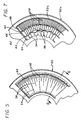
- Fig. 5 is an enlarged partial perspective view of an alternate thrust bearing underspring 50.
- the means for radially increasing the spring force of the underspring 50 of Fig. 5 comprises a spring element 52 including a first set of generally radially aligned ridges 54 which extend across the entire radial width of the spring element 52, and a second set of ridges 56 generally radially aligned and extending inward from the radially outer edge of the spring element a fractional portion of the radial width of the spring element 52.
- the ridges of the first and second sets of ridges 54, 56 are alternately spaced and have equal heights.
- the spring element 52 may further include a third set of ridges 58 extending radially inward a fractional portion of the width of the spring element 52.
- the ridges of the third set of ridges 58 are located between each of the ridges of the first and second set of ridges 54, 56.
- the second set of ridges 56 preferably extend radially inward approximately two-thirds of the width of the spring element 52 and the third set of ridges 58 extend approximately one-third of the width of the spring element 52.
- Figs 6A and 6B show alternative cross sections through the underspring 50 of Fig 5.
- Underspring 50 comprises a thin compliant ring disk having a thickness (t) generally between 0.0025 cm. and 0.075 cm.
- the cross sectional thickness, t1 of the underspring 50 may be uniform as shown in Fig 6A, alternatively, the cross sectional thickness of an underspring 50' may increase radially, from t1 to t2, as shown in Fig. 6B, wherein t1 is in the range of between 0.0025 cm. and 0.075 cm, and t2 is in the range of between t1 and sum of t1 + 0.075 cm.
- Increasing the cross sectional thickness further increases the spring force of the underspring 50' with increasing radius.
- Fig. 7 shows an alternative configuration for an underspring 50a similar to the underspring 50 of Fig. 5, including in addition at least one and preferably two slits 60, 62 in the spring elements 52a of the underspring 50a.
- the slits 60, 62 are preferably arcuate in shape, and divide the spring elements 52a into two or three segments 64, 66, 68.
- the slits 60, 62 are preferably located at the radially inner ends of the second and third sets of ridges 56, 58 respectively.
- the radially inner segment 64 includes one set of ridges
- the middle segment 66 includes two sets of ridges
- the outer segment 68 includes three sets of ridges.
- the underspring 50a of Fig. 7 can have either of the cross sections shown in Fig. 6A or 6B.
- the undersprings 50, 50a can have any of the orientations for the corrugations depicted in Fig. 2 and described above.
- the bearing disk 16 and underspring 20 (or 50, 50a) support the thrust runner 10 on a cushion of air or pressurized fluid.
- fluid film pressure increases radially to a maximum at the outer diameter due to the radial velocity gradient.
- the pressure between the relatively rotating thrust runner 10 and bearing disk 16 is dependent upon the relative velocity.
- the undersprings 20 of the present invention are designed to provide radially increasing stiffness to achieve uniform deflection and thus constant film thickness across the radial width of the foils 18. This in turn allows higher total bearing load capacities for the foil thrust bearings of the present invention.
- the undersprings 20, 50, or 50a are preferably formed by either a chemical etching or stamping operation, wherein the cutouts and slits defining the spring elements 32, 34, 36, 52, or 52a are made first and the corrugations 42, 44, 46 or ridges 54, 56, 58 are subsequently etched or stamped.
- the individual spring elements 32, 34, 36, 52, or 52a can be cut out of sheets, corrugated (or ribbed), and then attached to a metallic disk which includes the appropriately configured cutouts to accommodate the individual spring elements 32, 34, 36, 52, or 52a.
Landscapes
- Engineering & Computer Science (AREA)
- General Engineering & Computer Science (AREA)
- Mechanical Engineering (AREA)
- Physics & Mathematics (AREA)
- Fluid Mechanics (AREA)
- Support Of The Bearing (AREA)
- Springs (AREA)
Claims (6)
- Medienaxiallager, umfassend:
eine Axialläuferscheibe (10);
eine Axialscheibe (14), um die genannte Axialläuferscheibe drehbar abzustützen; und
ein nachgiebige Folien aufweisendes Lager (16, 18, 20; 50), das in betriebswirksamer Weise zwischen der genannten Axialläuferscheibe und der genannten Axialscheibe angeordnet ist, bei dem das genannte, nachgiebige Folien aufweisende Lager eine Lagerscheibe (16), die mit mehreren nachgiebigen Folien (18) ausgestattet ist, die zur genannten Axialläuferscheibe hin angeordnet sind, sowie eine Folienstützfeder (20, 50) umfaßt, die zwischen der genannten Axialscheibe und der genannten Lagerscheibe angeordnet ist, dadurch gekennzeichnet, daß die genannte Stützfeder ein Mittel umfaßt, um die genannten darüberliegenden nachgiebigen Folien mit radial zunehmender Federkraft abzustützen. - Medienaxiallager nach Anspruch 1, bei dem das genannte Mittel zur radialen Erhöhung der Federkraft der Stützfeder umfaßt:
mehrere Federabschnitte (30), bei denen jeder der genannten Federabschnitte zumindest zwei individuelle Federelemente (32, 34, 36) umfaßt, wobei jedes der genannten Federelemente individuell gewellt (42, 44, 46) ausgeführt ist und die genannten Federabschnitte jeweils so konfiguriert sind, daß sie eine der genannten darüberliegenden Folien (18) der genannten Lagerscheibe abstützen. - Medienaxiallager nach Anspruch 2, bei dem die genannten Federelemente (32, 34, 36) eines Federabschnittes in radial aneinandergrenzender Anordnung in gleichen Bogenwinkeln und in Querrichtung mit radial zunehmenden Bogenlängen verlaufen.
- Medienaxiallager nach Anspruch 2, bei dem die Wellungen (42, 44, 46) der genannten Federelemente eine zwischen den Wellenspitzen vorliegende Teilung (P) aufweisen und die Teilung (P) eines radial äußeren Federelementes geringer als die entsprechende Teilung (P) irgendeines entsprechenden radial inneren Federelementes ist.
- Medienaxiallager nach Anspruch 1, bei dem das genannte Mittel zur radialen Erhöhung der Federkraft der Stützfeder umfaßt:
ein Federelement (52), das einen ersten Satz von im allgemeinen radial ausgerichteten Rippen (54), die über die gesamte radiale Breite des genannten Federelementes verlaufen, sowie einen zweiten Satz von Rippen (56) umfaßt, die im allgemeinen radial ausgerichtet sind und von einer radial äußeren Kante des genannten Federelementes aus nach innen über einen Teilbereich der radialen Breite des genannten Federelementes (52) verlaufen, wobei die Rippen der genannten ersten und zweiten Sätze von Rippen (54, 56) einen wechselnden Abstand und die gleiche Höhe aufweisen. - Medienaxiallager nach Anspruch 1, bei dem das genannte Mittel zur radialen Erhöhung der Federkraft umfaßt:
eine zur Stützfeder gehörende dünne nachgiebige Ringscheibe (20), die eine Querschnittsdicke t₁ an einer radial inneren Kante und eine zweite Querschnittsdicke t₂ an einer radial äußeren Kante aufweist, wobei t₁ im Bereich zwischen 0,0025 cm und 0,075 cm und t₂ im Bereich zwischen t₁ und der Summe aus t₁ + 0,075 cm liegt.
Applications Claiming Priority (3)
| Application Number | Priority Date | Filing Date | Title |
|---|---|---|---|
| US07/667,689 US5110220A (en) | 1991-03-08 | 1991-03-08 | Thrust bearing underspring |
| PCT/US1992/001825 WO1992017708A2 (en) | 1991-03-08 | 1992-03-04 | Thrust bearing underspring |
| US667689 | 2000-09-22 |
Publications (2)
| Publication Number | Publication Date |
|---|---|
| EP0574550A1 EP0574550A1 (de) | 1993-12-22 |
| EP0574550B1 true EP0574550B1 (de) | 1995-11-29 |
Family
ID=24679230
Family Applications (1)
| Application Number | Title | Priority Date | Filing Date |
|---|---|---|---|
| EP92912139A Expired - Lifetime EP0574550B1 (de) | 1991-03-08 | 1992-03-04 | Stützfeder für Axiallager |
Country Status (5)
| Country | Link |
|---|---|
| US (1) | US5110220A (de) |
| EP (1) | EP0574550B1 (de) |
| JP (1) | JPH06505547A (de) |
| DE (1) | DE69206406T2 (de) |
| WO (1) | WO1992017708A2 (de) |
Cited By (1)
| Publication number | Priority date | Publication date | Assignee | Title |
|---|---|---|---|---|
| WO2025206431A1 (ko) * | 2024-03-28 | 2025-10-02 | 엘지전자 주식회사 | 스러스트 베어링 및 이를 구비한 터보 압축기 |
Families Citing this family (38)
| Publication number | Priority date | Publication date | Assignee | Title |
|---|---|---|---|---|
| US5318366A (en) * | 1992-08-24 | 1994-06-07 | Alliedsignal Inc. | Foil thrust bearing with varying radial and circumferential stiffness |
| US5248205A (en) * | 1992-08-24 | 1993-09-28 | Alliedsignal Inc. | Foil thrust bearing with varying radial and circumferential stiffness |
| US5529398A (en) * | 1994-12-23 | 1996-06-25 | Bosley; Robert W. | Compliant foil hydrodynamic fluid film thrust bearing |
| US5547286A (en) * | 1995-04-18 | 1996-08-20 | United Technologies Corporation | Hydrodynamic air thrust bearing with offset bump foils |
| US5902049A (en) * | 1997-03-28 | 1999-05-11 | Mohawk Innovative Technology, Inc. | High load capacity compliant foil hydrodynamic journal bearing |
| US5833369A (en) * | 1997-03-28 | 1998-11-10 | Mohawk Innovative Technology, Inc. | High load capacity compliant foil hydrodynamic thrust bearing |
| US5918985A (en) | 1997-09-19 | 1999-07-06 | Capstone Turbine Corporation | Compliant foil fluid thrust film bearing with a tilting pad underspring |
| US6224263B1 (en) | 1999-01-22 | 2001-05-01 | Alliedsignal Inc. | Foil thrust bearing with varying circumferential and radial stiffness |
| US6354741B1 (en) | 1999-01-22 | 2002-03-12 | Alliedsignal Inc. | Foil thrust bearing |
| US6702463B1 (en) | 2000-11-15 | 2004-03-09 | Capstone Turbine Corporation | Compliant foil thrust bearing |
| JP2003262222A (ja) * | 2002-03-08 | 2003-09-19 | Ntn Corp | フォイル軸受 |
| US20040066991A1 (en) * | 2002-10-03 | 2004-04-08 | R & D Dynamics Corporation | High load capacity foil thrust bearings |
| US6752533B2 (en) | 2002-11-15 | 2004-06-22 | Honeywell International Inc. | Foil thrust bearing cooling |
| KR20060015094A (ko) | 2004-08-13 | 2006-02-16 | 삼성전자주식회사 | 베어링 및 이를 포함하는 터보압축기 |
| US8147143B2 (en) * | 2004-09-22 | 2012-04-03 | Hamilton Sundstrand Corporation | Bump foil hydrodynamic thrust bearing |
| DE102004051400B4 (de) | 2004-10-21 | 2019-02-21 | Continental Automotive Gmbh | Axiallager für einen Rotor |
| US7948105B2 (en) * | 2007-02-01 | 2011-05-24 | R&D Dynamics Corporation | Turboalternator with hydrodynamic bearings |
| US8967866B2 (en) * | 2007-04-23 | 2015-03-03 | Hamilton Sundstrand Corporation | Hydrodynamic bearing |
| WO2011044110A2 (en) * | 2009-10-06 | 2011-04-14 | Mohawk Innovative Technology, Inc. | High speed machining center |
| KR100964883B1 (ko) * | 2009-10-07 | 2010-06-23 | 주식회사 뉴로스 | 트러스트 포일 에어베어링 |
| US9951784B2 (en) | 2010-07-27 | 2018-04-24 | R&D Dynamics Corporation | Mechanically-coupled turbomachinery configurations and cooling methods for hermetically-sealed high-temperature operation |
| JP5472170B2 (ja) * | 2011-03-18 | 2014-04-16 | 株式会社島津製作所 | 動圧気体軸受 |
| US9476428B2 (en) | 2011-06-01 | 2016-10-25 | R & D Dynamics Corporation | Ultra high pressure turbomachine for waste heat recovery |
| EP2910802B1 (de) * | 2012-10-16 | 2019-04-03 | IHI Corporation | Schublager |
| CN103291745B (zh) * | 2013-05-29 | 2015-12-23 | 南京航空航天大学 | 一种分离式波箔动压气体推力轴承 |
| US9470260B2 (en) | 2014-09-26 | 2016-10-18 | Hamilton Sundstrand Corporation | Thrust bearing assembly |
| JP6582431B2 (ja) * | 2015-02-10 | 2019-10-02 | 株式会社Ihi | スラスト軸受 |
| US10415634B2 (en) * | 2015-11-18 | 2019-09-17 | Hanon Systems | Air foil bearing |
| KR102485661B1 (ko) * | 2015-11-26 | 2023-01-09 | 한온시스템 주식회사 | 에어 포일 베어링 |
| US9926973B2 (en) * | 2016-06-13 | 2018-03-27 | Hamilton Sundstrand Corporation | Air bearing-corrugated thrust bearing disc |
| KR102552483B1 (ko) * | 2016-12-05 | 2023-07-06 | 현대자동차주식회사 | 에어 포일 스러스트 베어링 |
| EP3928886B1 (de) * | 2019-02-22 | 2023-11-22 | IHI Corporation | Druckfolienlager und verfahren zur herstellung einer grundplatte eines druckfolienlagers |
| KR102283021B1 (ko) * | 2019-03-15 | 2021-07-28 | 엘지전자 주식회사 | 터보 압축기용 스러스트 베어링 |
| JP7563357B2 (ja) * | 2021-10-06 | 2024-10-08 | 株式会社豊田自動織機 | ターボ式流体機械 |
| CN114110016A (zh) * | 2021-12-01 | 2022-03-01 | 中国商用飞机有限责任公司 | 止推轴承及轴承组件 |
| CN115419650B (zh) * | 2022-09-21 | 2025-07-25 | 深圳市英维克科技股份有限公司 | 一种压缩机及其推力轴承装置 |
| DE102023210860A1 (de) * | 2023-11-02 | 2025-05-08 | Robert Bosch Gesellschaft mit beschränkter Haftung | Lageranordnung eines elektrisch angetriebenen Verdichters |
| JP2026015965A (ja) * | 2024-07-22 | 2026-02-03 | 株式会社豊田自動織機 | フォイル軸受 |
Citations (2)
| Publication number | Priority date | Publication date | Assignee | Title |
|---|---|---|---|---|
| US4225196A (en) * | 1978-12-29 | 1980-09-30 | Mechanical Technology Incorporated | Hydrodynamic compliant thrust bearing |
| US4277111A (en) * | 1978-12-29 | 1981-07-07 | Mechanical Technology Incorporated | Support element for compliant hydrodynamic thrust bearing |
Family Cites Families (20)
| Publication number | Priority date | Publication date | Assignee | Title |
|---|---|---|---|---|
| GB1120624A (en) * | 1964-09-10 | 1968-07-24 | Glacier Co Ltd | Thrust bearing assemblies |
| US3635534A (en) * | 1969-08-06 | 1972-01-18 | Garrett Corp | Self-pressurizing bearings with resilient elements |
| US3747997A (en) * | 1971-07-22 | 1973-07-24 | Mechanical Tech Inc | Hydrodynamic foil bearings |
| US3809443A (en) * | 1971-08-05 | 1974-05-07 | Mechanical Tech Inc | Hydrodynamic foil bearings |
| US4082375A (en) * | 1976-12-17 | 1978-04-04 | United Technologies Corporation | Dual wedge fluid thrust bearing including wave spring |
| US4116503A (en) * | 1977-06-13 | 1978-09-26 | United Technologies Corporation | Resilient foil thrust bearings |
| US4170389A (en) * | 1977-09-21 | 1979-10-09 | Ampex Corporation | Foil bearing |
| US4213657A (en) * | 1978-12-29 | 1980-07-22 | Mechanical Technology Incorporated | Compliant hydrodynamic bearing with tubular support element |
| US4227753A (en) * | 1978-12-29 | 1980-10-14 | Mechanical Technology Incorporated | Compliant gas thrust bearing with profiled and apertured thrust runner |
| US4208076A (en) * | 1978-12-29 | 1980-06-17 | Mechanical Technology Incorporated | Compliant hydrodynamic bearing with improved support element |
| US4315359A (en) * | 1978-12-29 | 1982-02-16 | Mechanical Technology Incorporated | Hydrodynamic compliant thrust bearing and method of making |
| US4247155A (en) * | 1979-06-13 | 1981-01-27 | United Technologies Corporation | Resilient foil bearings |
| US4277112A (en) * | 1979-10-01 | 1981-07-07 | Mechanical Technology Incorporated | Stepped, split, cantilevered compliant bearing support |
| US4331365A (en) * | 1980-01-02 | 1982-05-25 | Mechanical Technology Incorporated | Nested Belleville spring support for compliant thrust bearings |
| DD154633B1 (de) * | 1980-11-28 | 1986-03-12 | Zeiss Jena Veb Carl | Fluidgleitlager |
| US4462700A (en) * | 1981-11-23 | 1984-07-31 | United Technologies Corporation | Hydrodynamic fluid film thrust bearing |
| US4624583A (en) * | 1984-10-01 | 1986-11-25 | The Garrett Corporation | Foil thrust bearing |
| JPS6192316A (ja) * | 1984-10-13 | 1986-05-10 | Taiho Kogyo Co Ltd | リ−フ型フオイルスラスト軸受 |
| US4682900A (en) * | 1985-12-19 | 1987-07-28 | The Garrett Corporation | Thrust bearing underspring |
| US4767221A (en) * | 1987-06-11 | 1988-08-30 | Williams International Corporation | Compliant hydrodynamic gas lubricated thrust bearing |
-
1991
- 1991-03-08 US US07/667,689 patent/US5110220A/en not_active Expired - Lifetime
-
1992
- 1992-03-04 WO PCT/US1992/001825 patent/WO1992017708A2/en not_active Ceased
- 1992-03-04 DE DE69206406T patent/DE69206406T2/de not_active Expired - Fee Related
- 1992-03-04 JP JP4511604A patent/JPH06505547A/ja active Pending
- 1992-03-04 EP EP92912139A patent/EP0574550B1/de not_active Expired - Lifetime
Patent Citations (2)
| Publication number | Priority date | Publication date | Assignee | Title |
|---|---|---|---|---|
| US4225196A (en) * | 1978-12-29 | 1980-09-30 | Mechanical Technology Incorporated | Hydrodynamic compliant thrust bearing |
| US4277111A (en) * | 1978-12-29 | 1981-07-07 | Mechanical Technology Incorporated | Support element for compliant hydrodynamic thrust bearing |
Cited By (1)
| Publication number | Priority date | Publication date | Assignee | Title |
|---|---|---|---|---|
| WO2025206431A1 (ko) * | 2024-03-28 | 2025-10-02 | 엘지전자 주식회사 | 스러스트 베어링 및 이를 구비한 터보 압축기 |
Also Published As
| Publication number | Publication date |
|---|---|
| WO1992017708A2 (en) | 1992-10-15 |
| US5110220A (en) | 1992-05-05 |
| DE69206406T2 (de) | 1996-04-25 |
| DE69206406D1 (de) | 1996-01-11 |
| JPH06505547A (ja) | 1994-06-23 |
| EP0574550A1 (de) | 1993-12-22 |
| WO1992017708A3 (en) | 1992-11-12 |
Similar Documents
| Publication | Publication Date | Title |
|---|---|---|
| EP0574550B1 (de) | Stützfeder für Axiallager | |
| EP0228251B1 (de) | Flüssigkeitsdrucklager | |
| US4668106A (en) | Thrust bearing underspring | |
| US5116143A (en) | High load capacity journal foil bearing | |
| US5911510A (en) | Bi-directional foil bearings | |
| US4296976A (en) | Cross-plies support element for compliant bearings | |
| EP0201642B1 (de) | Foliendrucklager | |
| EP0098741B1 (de) | Fluidumlager | |
| USRE39190E1 (en) | Compliant foil fluid film radial bearing | |
| US4871267A (en) | Foil thrust bearing | |
| US4300806A (en) | Multi-stage support element for compliant hydrodynamic bearings | |
| US5871284A (en) | Foil thrust bearing set | |
| US5961217A (en) | High load capacity compliant foil hydrodynamic thrust bearing | |
| US6964522B2 (en) | Hydrodynamic journal foil bearing system | |
| EP1208308B1 (de) | Folienaxiallager | |
| US4621930A (en) | Foil thrust bearing cooling | |
| US5938341A (en) | Foil thrust bearing including a follower spring having rotated, elongated spring tabs | |
| US4795274A (en) | Foil bearing | |
| US4451163A (en) | Foil bearing mounting carrier | |
| US4776077A (en) | Method of making a thrust bearing underspring | |
| EP0182535B1 (de) | Axiallager | |
| WO1992011469A1 (en) | Stepped foil journal foil bearing | |
| US4555187A (en) | Foil bearing alignment | |
| JP2553853Y2 (ja) | スラスト軸受装置 |
Legal Events
| Date | Code | Title | Description |
|---|---|---|---|
| PUAI | Public reference made under article 153(3) epc to a published international application that has entered the european phase |
Free format text: ORIGINAL CODE: 0009012 |
|
| 17P | Request for examination filed |
Effective date: 19930820 |
|
| AK | Designated contracting states |
Kind code of ref document: A1 Designated state(s): DE FR GB |
|
| RAP1 | Party data changed (applicant data changed or rights of an application transferred) |
Owner name: ALLIEDSIGNAL INC. |
|
| 17Q | First examination report despatched |
Effective date: 19950209 |
|
| GRAA | (expected) grant |
Free format text: ORIGINAL CODE: 0009210 |
|
| AK | Designated contracting states |
Kind code of ref document: B1 Designated state(s): DE FR GB |
|
| ET | Fr: translation filed | ||
| REF | Corresponds to: |
Ref document number: 69206406 Country of ref document: DE Date of ref document: 19960111 |
|
| PLBE | No opposition filed within time limit |
Free format text: ORIGINAL CODE: 0009261 |
|
| STAA | Information on the status of an ep patent application or granted ep patent |
Free format text: STATUS: NO OPPOSITION FILED WITHIN TIME LIMIT |
|
| 26N | No opposition filed | ||
| REG | Reference to a national code |
Ref country code: GB Ref legal event code: IF02 |
|
| PGFP | Annual fee paid to national office [announced via postgrant information from national office to epo] |
Ref country code: DE Payment date: 20080331 Year of fee payment: 17 |
|
| PG25 | Lapsed in a contracting state [announced via postgrant information from national office to epo] |
Ref country code: DE Free format text: LAPSE BECAUSE OF NON-PAYMENT OF DUE FEES Effective date: 20091001 |
|
| PGFP | Annual fee paid to national office [announced via postgrant information from national office to epo] |
Ref country code: FR Payment date: 20100318 Year of fee payment: 19 |
|
| PGFP | Annual fee paid to national office [announced via postgrant information from national office to epo] |
Ref country code: GB Payment date: 20100208 Year of fee payment: 19 |
|
| GBPC | Gb: european patent ceased through non-payment of renewal fee |
Effective date: 20110304 |
|
| REG | Reference to a national code |
Ref country code: FR Ref legal event code: ST Effective date: 20111130 |
|
| PG25 | Lapsed in a contracting state [announced via postgrant information from national office to epo] |
Ref country code: FR Free format text: LAPSE BECAUSE OF NON-PAYMENT OF DUE FEES Effective date: 20110331 |
|
| PG25 | Lapsed in a contracting state [announced via postgrant information from national office to epo] |
Ref country code: GB Free format text: LAPSE BECAUSE OF NON-PAYMENT OF DUE FEES Effective date: 20110304 |
|
| P01 | Opt-out of the competence of the unified patent court (upc) registered |
Effective date: 20230525 |