EP0573533B1 - A housing for electric circuitry packages - Google Patents
A housing for electric circuitry packages Download PDFInfo
- Publication number
- EP0573533B1 EP0573533B1 EP92906174A EP92906174A EP0573533B1 EP 0573533 B1 EP0573533 B1 EP 0573533B1 EP 92906174 A EP92906174 A EP 92906174A EP 92906174 A EP92906174 A EP 92906174A EP 0573533 B1 EP0573533 B1 EP 0573533B1
- Authority
- EP
- European Patent Office
- Prior art keywords
- cooling
- packages
- package
- cooling unit
- housing
- Prior art date
- Legal status (The legal status is an assumption and is not a legal conclusion. Google has not performed a legal analysis and makes no representation as to the accuracy of the status listed.)
- Expired - Lifetime
Links
Images

Classifications
-
- H—ELECTRICITY
- H05—ELECTRIC TECHNIQUES NOT OTHERWISE PROVIDED FOR
- H05K—PRINTED CIRCUITS; CASINGS OR CONSTRUCTIONAL DETAILS OF ELECTRIC APPARATUS; MANUFACTURE OF ASSEMBLAGES OF ELECTRICAL COMPONENTS
- H05K7/00—Constructional details common to different types of electric apparatus
- H05K7/20—Modifications to facilitate cooling, ventilating, or heating
- H05K7/20218—Modifications to facilitate cooling, ventilating, or heating using a liquid coolant without phase change in electronic enclosures
- H05K7/20254—Cold plates transferring heat from heat source to coolant
-
- H—ELECTRICITY
- H01—ELECTRIC ELEMENTS
- H01L—SEMICONDUCTOR DEVICES NOT COVERED BY CLASS H10
- H01L2924/00—Indexing scheme for arrangements or methods for connecting or disconnecting semiconductor or solid-state bodies as covered by H01L24/00
- H01L2924/0001—Technical content checked by a classifier
- H01L2924/0002—Not covered by any one of groups H01L24/00, H01L24/00 and H01L2224/00
Definitions
- This invention is directed to a housing accomodating a plurality of electric circuitry packages and resilient supporting and cooling units, and a combination of a housing including a cooling arrangement and a plurality of electric circuitry packages accomodated in the housing.
- the publication DE-33 21 320 describes a cage assembly with a stack of electric circuitry packages. In this cage assembly circuitry packages are rigidly fixed to frames of the cage.
- Patent abstracts of Japan Vol. 15, No. 159, E 59, abstract of JP 3-30399, published 8.2.91 a flexible cooling bag is principally described, said cooling bag being arranged to cool electric circuitry arranged thereto.
- the publication GB-A-1 231 268 describes a "removable printed circuit board interconnection assembly" including connector means and conductors in a so-called flat cable having connectors arranged side by side and being foldingly inserted into the insides of a plurality of U-shaped holders adapted to hold printed circuit boards for arranging contact with said connectors.
- the publication CH-A-422 937 describes first frames for holding electric circuit boards in a cage configuration and second frames for further assembling of the first cage configured electric circuitry assemblies. Cooling is by normal convection of air, the boards being vertically mounted.
- Another aspect which has to be considered is how to establish contact in a multitude of points in an easy, realiable and cost-effective way. This aspect is specially important when contacting complex electronics which have a multitude of inputs and outputs which are to be contacted.
- cooling has been provided in a variaty of ways of which a few will be described below.
- the cooling fluid could be a liquid or a gas, e.g. air.
- One way to provide cooling, often used for cooling computer electronics, is to integrate a fan into an outer housing of the computer or outside the computer, which fan provides a flow of air through the electronics. The air can be cooled or just be of normal room temperature.
- Another cooling technique which has been used includes spraying the surface of the chip with a liquid, which evaporates when striking the surface.
- Yet another cooling technique which has been adopted for cooling certain supercomputers involves sinking the whole device including the electronics into a cooling liquid.
- the device has to be drained before access of a part of the device.
- the liquid used has to fulfill high requirements.
- the object of the invention is to provide a housing for accomodation of a plurality of packages, e.g. including wafer sized VLSI-chips, where the packages are power supplied, electrically connected, mechanically supported, and cooled.
- the housing should withstand and protect the packages from severe environmental conditions, such as shocks, vibrations, e.g. 30G, a wide range of temperatures, e.g. -55 to +40 C, with related thermal expansions, and high altitudes, e.g. 20 km.
- the housing should also include few parts, be suitable for mass production, have a low price, and allow for wide manufacturing tolerances.
- Another object of the invention is to provide a cooling technique, which provides effective cooling of the packages.
- Still another object of the invention is to provide flexible electrical connection of the packages.
- the object of the invention is achieved by a housing with a rigid cage assembly as defined in claim 1 and a combination of a housing including a cooling arrangement and a plurality of electric circuitry packages as defined in claim 14.
- cooling units By means of the flexible walls of the cooling units good thermal conductivity can be obtained.
- cooling units provide added resilient support to the packages, when incorprated in a housing.
- the frame could be provided with projections fitting in corresponding slots provided in the support rods.
- the height of the projections decides the minimum distance between the packages.
- the rigid frame walls provides added support of the packages.
- the frame direct the expansion of the cooling units toward the packaged.
- the frames also positions the packages by deciding the minimum distance between them.
- the cooling unit inlets and outlets are releasably connected to at least one cooling fluid inlet tube and at least one cooling fluid outlet tube, respectively.
- the tubes are held in place by the end frames.
- the tubes transport the cooling fluid between the the cooling units and a cooling fluid source.
- the tubes transport the cooling fluid to and from the cooling units in a simple and cost effective manner.
- each cooling unit includes a cooling bag made of a flexible material held in the cooling unit frame.
- a electrical connection arrangement including a plurality of connector and wire assemblies for the electrical connection of a plurality of electric circuitry packages accomodated and stacked in a housing, each connector and wire assembly characterized in the combination of:
- An electrical connection arrangement could be provided, whereby the flexible connections allow slight package movement as well as package size differences.
- each connector and wire assembly includes a plurality of resilient connector assemblies mounted to a plurality of backplanes, which are mounted to the support rods, each connector assembly contacting a plurality of wires for data communication and power supply to a plurality of contact points provided on each package.
- each connector assembly is mounted over a package by means of resilient contact springs.
- each connector assembly is mounted inbetween the packages by means of the resilient contact springs.
- the connector assemblies allow a multitude of contact points to be established. Each connector assembly could establish several hundred contact points.
- Power wires could be included in one or more power wire layers provided in the flat cable. As an alternative a separate power bus could be used.
- each connector assembly includes a connector provided with two horizontal rows of contact springs.
- the electrical contact between the data wires of a flat cable and the data package pads of a package is established by means of at least some of the plurality of contact springs, each pressing a number of flat cable contact pads against a corresponding number of data package pads, putting the points of contact under pressure.
- the contact springs provide means for establishing a multitude of contact points. They also allow package thickness differences.
- the power wires When the power wires are included in a flat cable it is to prefer to establish contact between the wires and the power package pads of a package in the same way as contact is established between data wires and data package pads, i.e. by indirect contact by means of the contact springs and a flat cable.
- the power wires When the power wires are provided in a separate power bus it is to prefer to establish direct contact, i.e. the contact springs are in direct contact with the power wires and the power package pads of a package.
- a housing 1 which can accomodate a plurality of packages 2.
- a package 2 could for instance be a substrate holding and supporting a chip or some other container for electrical circuitry, whereby electrical connection from the chip to the edges of the package can be provided by conductors buried in the substrate of the package.
- the chip, and thereby the package could vary in size and even include an entire wafer.
- the present invention is particularly advantageous for large packages, which include large chips. Since the exact structure of the package is not a part of the actual invention it is not described in detail.
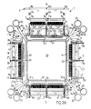
- the housing 1 includes a cage assembly, including two end frames 3,4 (of which one is shown in Fig 2C) connected with each other by means of support rods 5.
- the packages 2 are stacked on top of each other in the cage assembly.
- each package is 6" x 6" large. It is of course within the scope of the invention to provide a housing which can accomodate another number of packages, possibly being of a completly different size than the suggested. The number of packages could for instance be 17.
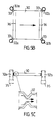
- FIG. 1 shows, from above, a cut along the dashed line IIA of the housing 1 in Fig. 1.
- the housing 1 is symmetrical - the four sides (North N, South S, West W, East E) looks the same (see Fig 2A, and 2C) and the bottom looks the same as the top (see Fig 1).
- four connector assemblies are provided; on side N the connector assembly and related parts are shown exploded (see also Fig 2B), on side E the connector assembly is in place and contact is established between a package and a flat cable 10 (not shown in Fig 2A), on side S and side W two intermediate steps are shown.
- the connector assemblies will be further explained in conjunction with the description of Figs 3A to 3E.
- Fig 2B shows the same connector assembly 27 with related parts on the side N of the housing 1 as in Fig 2A, but enlarged.
- the housing 1 in Figs 1, 2A and 2C includes means for :
- the mechanical means could for instance, as shown in Figs 1, 2A and 2C, include a cage assembly, which mechanically supports the packages and other parts provided in the housing 1 and which includes two end frames 3,4, eight support rods 5 (of which only four can be seen in Fig. 1) and four backplanes 6 (of which only three can be seen in Fig. 1).
- the mechanical support means cooperates with the cooling means and the electrical connection means in order to support the packages resiliently.
- the cage assembly is described further below.
- the means for supplying power could include one or several traditional power supplies. Although aspects of the power supplies important for the present invention will be described further below, the exact structure of a power supply is not described in detail since it is not part of the present invention.
- the cooling means includes a plurality of cooling units preferably containing a flowing cooling fluid, such as a liquid (e.g. water) or a gas (e.g. air).
- the cooling units are sandwiched with the packages 2 into a stack in which a cooling unit is provided both above and below each package 2.
- Tubes 32 for inlet and outlet of the cooling fluid in to and out from each cooling unit are provided in the housing.
- the thermal path is from the package through a cooling unit wall to the cooling fluid.
- the cooling fluid is put under pressure and it is preferred that at least the package facing walls of the cooling unit are made out of a flexible material. The flexible walls adjust in form to the surface of the package and good thermal conductivity can be obtained.
- the cooling means are described further below.
- each connector assembly 27 could create contact to both sides of an individual package 2 (see Fig 3F).
- each connector assembly 27 creates contact between two packages 2, i.e. contact is created between the underside of one package 2 and the overside of the package below (see Fig 7A).
- a first connector assemblies 27 provides springs on all four sides of a package.
- the springs could be integrated in the connector assemblies 27 connecting the packages electrically, whereby electrical contact can be maintained even if the package moves.
- the springloaded connection is also advantageous when it comes to allowing package size differences since a difference in size of a package only results in a different tension of the springs, i.e. greater tension for a larger package and less tension for a smaller package.
- the size differences could for instance be caused by thermal expansion or wide manufacturing tolerances.
- the packages are connected to each other and possibly to the outside world, e.g. a computer.
- the packages are also connected to the power supplies.
- the electrical connection means, including the connector assemblies 27, are described further below.
- the parts included in the housing 1 can be divided functionally into four main groups, where each group can be regarded as a certain subsystem providing a certain function/mechanism.
- the housing 1 includes means for : 1) electrical connection 2) cooling 3) mechanical support 4) power supply.
- the cooling means also provides mechanical support to the packages.
- resilient suspension of the packages is accomplished by the co-operation between the mechanical, cooling and electrical connection means.
- a first electrical connection means will be described below.
- electrical connection means which includes four connector and wire assemblies, one for each side N,S,W,E of the housing 1.
- Each assembly includes a plurality of connector assemblies 27, at least one external terminal 11, and at least one flat cable 10.
- a first connector and wire assemblies there are four flat cables 10, each flat cable possibly being in contact with an external terminal 11 at each end for connection with the outside and it is also in contact with each package 2 along one of the four sides N,S,W,E of the housing by means of the connector assemblies 27 at that side.
- the flat cables 10 along the sides N,S are connected to the upper power supply 8 and the flat cables 10 along the sides W,E are connected to the lower power supply 9.
- a connector assembly 27 provides the electrical contact between a package 2 and the flat cable 10 by pressing the flat cable 10 against the package 2 (see Fig 3F and Fig 7A).
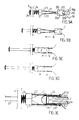
- a first connector assembly 27 shown from the side in Fig 3A and from above in Fig 2B includes three locking washers 26, three shock springs 24, one connector 7 provided with a plurality of contact springs 23, a guide 12 with three registration pins 21, a flat cable 10 and a contact spring separator 22, henceforth also called separator 22.
- the four flat cables 10 are used for distribution of data and power and for establishing contact with the packages 2.
- Each flat cable 10 is a film including a plurality of layers, which for instance could include data or power wires or contact pads for contacting the packages.
- a flat cable 10 could for instance have the size 102x680 mm and the thickness 400 micrometer.
- Each layer could for example be built from a polymide base coated with copper.
- each flat cable is provided with a plurality of openings 10a in order to allow the flat cable 10 to be threaded onto the registration pins of all the connector assemblies on one side N;S;W;E of the housing 1. If there are sixteen connector assemblies provided on a side N;S;W;E, each connector assembly having three registration pins, which is the case in the preferred embodiment, there are sixteen times three, i.e. 48, openings 10a in each flat cable. In Fig 4A two times three openings 10a are shown.
- a number of contact layer pads 102 are provided in the contact layer corresponding to the number of package pads 20 provided on the packages 2.
- the size of the flat cable contact pads 102 matches the size of the package contact pads 20.
- the size of the pads could be 1x1 mm.
- At least one power wire Vdd is provided for the voltage supplied and at least one power wire Gnd (ground) is provided.
- at least one power wire Gnd ground
- four power wires Vdd are provided in one power wire layer 103 and one power wire Gnd is provided in the second power wire layer 103. In this way a low impedance transmission can take place, which is important since the power includes very high frequency components, in the range of 100 MHz. Power is distributed as 5V and typical current is 18A.
- the data communication is performed on transmission lines, each using three wires 106 within the same data wire layer 105. In total there could be 32 transmission lines in each layer.
- the power wire layers 103 are placed on both sides of the data wire layers 105 (see Fig. 4B).
- each package is provided with three rows of package contact pads 20 at each side N,S,W,E.
- Each package contact pad 20 is in contact with a conductor 19 (Fig 3E), which is buried in the package substrate.
- Fig 3E the connection of each of the pads 20 to the flat cable 10 (see Fig 3E) is provided by an individual contact spring 23 of the connector 7.
- Each connector 7 is provided with two horizontal rows of contact springs, each row including a number of contact springs 23 which could correspond to the number of package pads 20 to be contacted.
- the length of each contact spring corresponds to the distance that the contact spring has to extend in over the package in order to establish contact with its corresponding package pad 20.
- each contact spring 23 could be long in order to take up large tolerances on the package thickness.
- each contact spring 23 could have one of three different lengths depending on in which row its corresponding package pad 20 is situated. It is of course within the scope of the invention to provide the package with another number of package pad rows, whereby the connector contact springs have a corresponding number of different lengths.
- all contact springs of the two horizontal rows could be of the same length, all being able to reach the package pad row furthest away from the edge of the package, whereby each contact spring could establish contact between a number of flat cable pads and a corresponding number of package pads 20.
- the contact springs 23 in each horizontal row are formed in one unit, e.g. by pressing, which unit is integrated into one half of the plastic body of the connector 7. Two such units integrated in two such plastic body halves are mounted together, e.g. with a clips (not shown), to form one connector 7.
- the plastic body of the connector 7 is provided with a number of openings 7a corresponding to the number of registration pins of a guide 12 (see Fig 2B).
- the contact springs 23 could be electrically isolated from the flat cable wires, e.g. by being coated by a plastic material or by means of an isolating layer in the flat cable facing the contact springs 23.
- contact springs 23 could be in electrical contact with one or several package pads by means of direct ohmic contact, i.e. without the flat cable.
- This technique can be used to supply power, thereby eliminating the need for power layers and power wires in the flat cable 10, whereby power for instance could be supplied via power busses 13 (see Fig 7A) to the contact springs in question by means of one or more electrical contacts provided at the back of the connector body.
- the centre of the connector 7 is provided with a lip 7b, which fits in a corresponding cut-out 2a provided in the package 2 (see Fig 2B).
- the connector registers accurately to the package.
- Each guide 12 is provided with a plurality of registration pins 21 adapted to pass through matching openings provided in the connector assembly elements.
- each guide 12 is provided with three registration pins 21 and each connector assembly element is provided with three corresponding openings (see Fig 2B).
- the registration pins of the guide 12 are in turn passed through matching openings 10a provided in a flat cable 10, matching openings 22a provided in a separator 22, matching openings 7a provided in the body of a connector 7, through the shock springs 24 and finally through corresponding openings 6a provided in a backplane, thereby guiding the connector assembly elements (see Fig 2B).
- the diameter of the openings 6a of a backplane 6 are larger than the diameter of the registration pins 21 in order to allow an individual connector assembly to move relative the backplane in question.
- a locking washer 26 is mounted on each registration pin 21 in order to hold the connector assembly "hanging" in the backplane 6.
- the locking washers 26 are only needed to allow preassembly of the connector assemblies 27 and may be removed when the housing is assembled.
- the separator 22 separates the two horizontal rows of connector contact springs 23 in order to establish contact between the package pads 20 and the flat cable 10 (see Fig. 1 and Fig. 3E).
- the separator 22 (see Fig 3A) is provided with two sloping surfaces 22c, 22d which together forms an arrow-shaped separator body pointing towards the connector 7.
- the sloping surfaces could extend along the full horizontal length of the separator 22.
- the sloping surfaces 22c, 22d only extend along the horizontal sections which corresponds to the horizontal sections of the connector provided with contact springs, i.e. along the full length except around the openings 22a.
- One shock spring 24 is provided on each registration pin 21 in order to allow for package size variations and slight package movement and in order to help holding the connectors in place when connected.
- Figs 3A and 3B shows a connector assembly in the unconnected state as a side view of a cut along the dashed line C1 in Fig 2A, i.e. as a cut through the connector assembly on the side W of the housing 1.
- Fig 3C shows a connector assembly in an intermediate state as a side view of a cut along the dashed line C2 in Fig 2A, i.e. as a cut through the connector assembly on the side S of the housing 1.
- Figs 3D and 3E shows a connector assembly in the connected state as a side view of a cut along the dashed line C3 in Fig 2A, i.e. as a cut through the connector assembly on the side E of the housing 1.
- a guide 12 provided a film forming surface 12b is shown in Fig 3A.
- the guide 12 is also provided with three registration pin 21 (of which only one is shown in Fig 3A), on which several connector assembly parts are mounted and on which the parts can slide.
- the parts can slide and be positioned since they are provided with openings corresponding to the registration pins 21 (see side N in Fig 2A and 2B).
- Each registration pin 21 is put through a corresponding opening 6a in a backplane 6 and is provided with a locking washer 26 at the "non-package" end.
- the sliding parts includes, in order from the "package” end, a separator 22, a connector 7 provided with contact springs 23, and a shock spring 24.
- the two horizontal contact spring rows presses against each other in the unconnected state.
- the separator 22 is provided with a film forming surface 22b which fits with the film forming surface 12b of the guide 12.
- Fig 3B the two matching film forming surfaces 12b and 22b are pushed together with the flat cable 10 fixed inbetween.
- the surfaces 12b, 22b have the function of positioning and smoothly bending the flat cable 10.
- the contact springs 23 of the connector 7 are in contact with the separator 22, which in Fig 3C has separated the contact springs 23 due to the pushing movement in the direction of the arrow B.
- Fig 3D the connector 7 is in place and contact is established between the flat cable 10 and the package in question (see Fig 3E).
- the shock spring 24 is slightly tensioned, which helps holding the connector 7 in place.
- Fig 3E shows the connector 7 in place over the edge of a package.
- the contact springs 23 of the connector 7 presses the contact pads 102 of the flat cable 10 against the package pads 20, whereby electrical contact is established.
- the package pads 20 are in contact with conductors 19 buried in the substrate of the package 2.
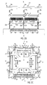
- Fig 2C shows four external terminals 11 mounted to the top end frame 3. There are preferably one external terminal 11 electrically connected to each end of each flat cable 10. If there are four flat cables 10 in an embodiment of a housing 1 then there are eight external terminals 11 provided, four at each end of the housing 1.
- the external terminals 11 are used for data communication from the packages 2 to "the outside world" and to the packages 2 from "the outside world".
- the outside world could for instance be a conventional computer, e.g. a PC, workstation or a mainframe computer, an external network or another stack of packages. It is obvious for a person skilled in the art to perceive other possibilities, e.g. connecting a plurality of housings 1 whereby the electrical connection could be provided by connecting the external terminals 11.
- the external terminals 11 could be standard type terminals, e.g. a socket with a corresponding plug which fits into the socket, i.e. a plug and socket arrangement.
- a plug and socket arrangement i.e. a plug and socket arrangement.
- four standard type sockets are provided as the four external terminals 11. The only requirement is that the terminal 11 used has to be able to establish contact with at least some of the data wires in the flat cable.
- a plurality of cooling units are provided inbetween the packages. Or more specific; one cooling unit is provided on top of each package and an additional cooling unit is provided inbetween the lower power supply 9 and the bottom package in the stack (see Fig. 1).
- the cooling units preferably contains a liquid as cooling fluid, e.g water.
- the cooling fluid could be a gas, e.g. air.
- Cooling of each package 2 is provided by cooling means including a plurality of cooling units provided with inlets 30a and outlets 30b for allowing the cooling fluid to flow through the unit in question, each unit including or being supported by a cooling unit frame 31.
- the cooling means further includes a plurality of tubes 32 for transporting the cooling fluid, tube connections 33 for connecting the cooling unit inlets 30a and outlets 30b to the tubes 32, tube clamps 34 for holding the tube connections in place, and a plurality of end clamps 35 placed at the open ends of the tubes.
- At least the package facing walls of the cooling unit 30, 31, 33, 34 are made of a flexible material which adjust in form to the package surfaces due to the cooling fluid pressure.
- Each cooling unit 30, 31, 33, 34 includes a cooling unit frame 31 providing rigid walls perpendicular to the package facing walls of the cooling unit 30, 31, 33, 34. The rigid walls restrict the direction of the cooling unit expansion, which is caused by the fluid pressure, so that the cooling unit expand towards the packages, putting the flexible walls in pressurized contact with the packages, which creates good thermal conductivity.
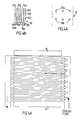
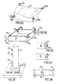
- Fig 5E shows a cooling unit frame 31 provided with projections 31a with a certain height, whereby the frames 31 could be stacked on top of each other in the housing 1, thereby deciding the minimum distance between the packages 2.
- Each cooling unit frame 31 is supported by a plurality of support rods 5 as will be described further below, in the mechanical support section.
- Each cooling unit could include a cooling bag 30 made out of a flexible material, preferably a polymer material, which bag 30 is placed in the supporting cooling unit frame 31, which holds the bag 30 during assembly and non-pressurized periods.
- the bag 30 is removably mounted to the frame 31, which is shown in Fig 5G.
- a cooling bag 30 is shown from above in Fig. 5B, in which the arrow indicates the direction of flow.
- the inlets 30a and outlets 30b of the cooling bag 30 of Fig 5B are connected to a set of four tubes 32, two inlet tubes 32a and two outlet tubes 32b by means of tube connections 33.
- a cooling bag 30 provided with inlets 30a and outlets 30b extending slightly from the bag 30 is shown as a perspective view in Fig 5D.
- a cooling frame 31 for holding the bag 30 of Fig 5D is shown as a perspective view in Fig 5E.
- the cooling frame 31 is provided with four openings 31b through which corresponding inlets 30a and outlets 30b of the bag 30 can be put, whereby the inlets 30a and outlets 30b could be threaded short metal pipes fixed to the frame 31 by nuts (not shown).
- each cooling unit includes a plurality of separate sections, preferably one separate section in which the cooling fluid is stationary, henceforth called the stationary section 30d, and two separate sections along the flexible package facing walls in which the cooling fluid is flowing, henceforth called the flowing sections 30c.
- the stationary section 30d preferably contains a pressurized fluid and is preferably provided with at least slightly flexible walls, each wall separating the stationary section 30d from the flowing sections 30c.
- Each flowing section 30c is provided with at least one inlet and one outlet. All sections are removably or fixedly mounted to the cooling unit frame 31.
- each cooling unit includes four supporting rigid walls forming a cooling unit frame 31, perpendicular to and attached to the two flexible package facing walls, forming a box-like unit.
- This alternative is illustrated in Fig 5H, in which the flexible walls are fixedly mounted to the frame 31.
- the cooling unit frame 31 is integrated in a cooling bag 30, whereby the rigid walls of the cooling unit frame are fixed to the inside of the cooling bag 30.
- each tube 32 is provided with a plurality of openings 32c for inlet of the cooling fluid to the cooling unit and/or outlet of the cooling fluid from the cooling unit (see Fig 5F).
- the tube openings 32c could extend horizontally from the tube 32 creating a short pipe to which one end of a tube connection 33 could be attached by means of a tube clamp 34, whereby the cooling unit end of the tube connection 33 could be permanently fixed in the cooling unit or as an alternative be attached to it by means of another tube clamp 34.
- a set of four tubes are connected to each cooling unit by means of four tube connections 33. Two of the tubes 32 act as inlets and two of the tubes 32 act as outlets.
- Each tube or alternatively each pair of tubes, is provided with an end clamp 35 located at the bottom end of each pair of tubes 32 for keeping the pressure of the cooling fluid when the tubes are disconnected, i.e. the cooling fluid should remain in the cooling system of the housing 1 even if disconnected from a cooling fluid source (see Fig 5F).
- the end clamps automatically closes the openings when the cooling means are disconnected, thereby preventing leakage of the cooling fluid.
- the end clamps 35 could be of snap type.
- the flow of a cooling fluid through the cooling system is shown schematically in Fig. 5A, where the direction of the flow is indicated by the arrows.
- the cooling fluid is put under pressure and flows from the inlet tubes 32 to the outlet tubes 32 through the cooling units, thereby cooling the packages 2.
- the thermal path is from the package to the cooling fluid through the flexible walls of the cooling unit, which have to sustain the pressure forces why a sufficiently strong material is to be preferred, e.g. polyamide laminated by polythene. Since at least the package facing walls are flexible there will be good thermal conductive contact when the cooling fluid pressure causes the bag walls to press against the package.
- contact pressure between the cooling units and the packages in the stack can be provided by tightening a mechanical joint, which is mounted over the stack.
- the mechanical joint can include support rods which can be tightened by screws, which will be described further below, in the mechanical support section.
- a cooling bag 30 and a flow throttle 37 is shown from the side in Fig. 5C.
- the arrows indicate the direction of flow. Even though there are preferably seventeen cooling bags 30 in this embodiment, for simplicity only one is shown in Fig. 5C.
- Each cooling unit could be provided with one inlet 30a and one outlet 30b, or alternatively, with two inlets 30a and two outlets 30b, which is to be preferred.
- the cooling fluid could be more evenly distributed.
- the cooling means can be provided with flow control means to control the cooling distribution, e.g. the flow rate can be controlled to increase/decrease the cooling of specific areas or for ensuring even cooling of an area or both.
- FIGs 5B and 5C Two flow control means are shown in Figs 5B and 5C, respectively.
- the cooling bag 30 is provided with walls 36 provided with nozzle holes and placed to form a channel together with the inlet and outlet edge.
- the cooling bag 30, now seen from the side is provided with a flow throttle 37 for increasing the flow rate.
- the flow rate can be increased by inserting horizontal planes (not shown) in the cooling bag which decreases the vertical crossection area of the bag.
- the flow throttle 37 in Fig 5B can be used to compensate for the cooling fluid pressure drop. Without any flow control means the cooling fluid pressure is less in the cooling bags 30 furter away than in bags 30 closer to the cooling fluid source.
- the bags 30 with differently sized flow throttles 37, i.e. bags 30 closer to the cooling fluid source are provided with throttles with smaller openings and bags 30 further away are provided with throttles with larger openings, the cooling fluid pressure drop can be compensated and the fluid pressure can be close to the same in all cooling bags 30.
- the packages 2 are supported mechanically by an cage assembly 3,4,5,6 including two end frames 3,4, eight support rods 5 (of which only four can be seen in Fig. 1) and four backplanes 6 (of which only three can be seen in Fig. 1).
- each package 2 there are preferably four connector assemblies 27, each having a multitude of connector elements.
- the resilient connector assemblies 27 allow each package 2 in the stack to move slightly in order for them to take up package size differences.
- the support rods 5 could be made of extruded aluminum. In an embodiment of the present invention there are two support rods on each side of the housing 1 (see Fig 2A and 2C). Or more sepecific; there are eight support rods 5, one on each side of each of the four corners of the housing 1. Along the full length of one side of each support rod 5 there is a slot 5a, which in shape corresponds to the shape of projections 31a provided on the cooling unit frame 31 (see Fig 5E). By placing each of the four projections 31a of each cooling unit frame 31 in a corresponding slot 5a in four of the support rods 5, the cooling means are supported mechanically. In addition, the distance between two packages can be decided by the height of the cooling unit frame 31 or the height of the projections 31a of the cooling unit frame.
- the cooling unit frames 31 reinforce the cage assembly and provides added mechanical support by the way they are mounted in the support rods 5.
- Fig 2C the housing 1 is shown from above.
- the two end frames 3,4 are mounted on the support rods 5, e.g. by using screws.
- the upper power supply 8 is mounted to the top end frame 3, as shown in Fig 2C
- the lower power supply 9 is mounted to the bottom end frame 4, in the same way as shown in Fig 2C for the top end frame 3.
- Each end frame could be shaped like an double-crossed H (see Fig 2C).
- the end frames take up the pressure acting towards the power supplies by supporting the power supplies in a plurality of points.
- the end frames could also act as holders for the tubes 32.
- the tubes are mounted to the support rods 5.
- the four backplanes 6 are mounted on the support rods 5, e.g. by screws (not shown).
- the backplanes 6 could for instance be made of a moulded plastic material and could be provided with a plurality of openings 6a (see Fig 1) through which the registration pins 21 can extend.
- the openings 6a of each backplane 6 provide a coarse positioning of the connectors 7 and also allow preassembly of the connector assemblies 27. The positioning is coarse since the openings 6a are larger than the corresponding registration pins 21.
- Each of the power supplies include several power supply units operating in parallell - if one power unit fails the other units remain in operation. This technique increases the reliability.
- Fig 1 power is supplied to the packages 2 by an upper power supply 8 and a lower power supply 9.
- the upper power supply 8 is mounted at the top in the cage assembly 3,4,5,6 and the lower power supply 9 is mounted at the bottom in the cage assembly 3,4,5,6.
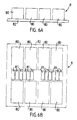
- Figs 6A and 6B shows a power supply 8, 9, which could be provided in the housing 1 according to the invention.
- the housing 1 is provided with two power supplies 8, 9 of this kind.
- the lower power supply 9 is similar to the upper power supply 8, except for that it is mounted at the bottom of the housing instead of at the top. Another difference is that they are rotated 90 degrees relative each other. For the purpose of simplicity, only the upper power supply 8 will be described below.
- the upper power supply 8 in Figs 6A and B includes a plurality of power supply units 80, henceforth also called power units, and a plurality of high current capacitors 81 (see Fig 6B), henceforth also called capacitors.
- the number of power units 80 is preferably eight for each power supply and the number of capacitors 81 is preferably twelve for each power supply. Since the exact structure of the power unit 80 is not a part of the actual invention it is not described in detail.
- All power units 80 are connected to one high voltage mains connector 83 (see Fig 2C), e.g. 311 V DC (Direct Current).
- the mains is decoupled by the high current capacitors 81, which for example could have the characteristics 0.47 microF/ 400 V.
- the power supply shown in Figs 3A and 3B is mounted on a heat sink 82, which with its underside is in contact with a coolinq bag 80.
- the heat sink 82 also provides mechanical support against the cooling bag pressure.
- the heat sink 82 could be made of a metal or some kind of cheramic material.
- the two end packages in the housing could include transformers for the power supply means 8;9.
- Power is distributed from the power supplies 8,9 to the packages 2 by a plurality of flat cables 10 including power wires or by a plurality of power busses 13.
- Each power supply 3;9 supplies two sides each. This has been described above in conjunction with the description of the electrical means.
- a plurality of power busses 13 could be provided in the housing, separate from the flat cables 10 (see Fig 7A). This scheme is described further below in conjunction with the description of a second embodiment of the housing 1.
- the housing could be provided with sixteen Vcc busses, eight from the upper power supply 8 and eight from the lower power supply 9.
- the connector assemblies 27 are provided with shock springs, preferably three at each side of the package, the packages are allowed to move slightly in the horizontal plane.
- the cage assembly forms one unit and each package with four connector assemblies 27 form one unit.
- the units are physically connected by springs and the cooling fluid pressure.
- the cooling units in the stack When the cooling units are in pressurized contact with the packages by means of the pressurized cooling fluid, the cooling units in the stack together forms a large “cushion” absorbing shocks and vibrations. In addition, the "cushion” allows the packages to move sligthly in the vertical direction.
- the cooling units also provides mechanical support in that the friction caused by the pressurized contact with the packages "stabilizes" the packages in the stack, preventing them from moving around to much in the cage assembly. If for example the cooling fluid is under pressure, about 100 Kpa, the forces between the cooling bag 30 and the package is about 1,5 kN. It causes a friction which may sustain side forces of approximately 500 kN. Thus the package movement in the horizontal plane is, in most cases, caused by the torsion of the cooling bags, e.g. when the housing is tilted.
- the horizontal component of a force caused by a shock is handled by the support rods 5 and/or the shock springs of the connector assemblies and the vertical component is handled by the flexible cooling units. They work in co-operation with eachother in order to absorb external forces.
- a shock causes horizontal package movement, the packages presses against one, or possibly two of the sides of the housing, i.e. against the backplanes on these sides, whereby the support rods 5 take up the forces.
- Manufacturing of the parts included in the housing does not have to fulfill restrictive tolerance requirements since the parts and the housing is designed to allow for wide tolerances.
- the packages does not have to be of exactly the same size since they are connected with springloaded connector assemblies 27.
- a fairly large pad size, e.g. lxl mm can be provided because of the large package size, e.g. 6x6 inches. This also ensures easy assembling.
- a second embodiment of a housing according to the invention will be described below.
- the housing is provided with connector and wire assemblies of a different kind than in the first embodiment described above.
- each connector assembly 27 creates contact between two packages 2, i.e. contact is created between the underside of one package 2 and the overside of the package below 2.
- the wiring includes a plurality of power busses 13, which are connected to the power supplies and which extends along the full length of each side N,S,W,E of the housing 1.
- each power bus 13 preferably including at least one power wire Vcc and at least one power wire Gnd and each power bus 13 preferably being connected to a power unit 80.
- Data can be communicated from each package to every other package in the housing via intermediate packages and flat cables 10 situated inbetween the two packages that need to communicate.
- the plurality of flat cables 10 are used for distribution of data and for establishing contact with the packages 2.
- Each flat cable 10 is a film including at least one electrically conducting layer, which include data wires 106 and/or contact pads 102 for contacting the packages.
- Power is supplied directly to the power package pads 20b via some of the plurality of contact springs 23 provided by each connector assembly 27, the power supplying contact springs 23b being in contact with the power busses 13, thereby eliminating the need for power wires (and power wire layers) in the flat cable 10.
- the signal contact springs 23a are electrically isolated from the flat cable 10, each signal contact spring 23a having the function of establishing a point of contact between a number of contact pads 102 of the flat cable 10 and a corresponding number of signal package pads 20a. The number of contact points established by each individual contact spring 23 could be choosen according to the application.
- a number of contact layer pads 102 are provided in the contact layer corresponding to the number of package pads 20 provided on the packages 2.
- the layer itself is preferably electrically isolating, except for the contact pads 102.
- the size of the flat cable contact pads 102 matches the size of the package contact pads 20.
- the size of the pads could be 1x1 mm.
- the flat cable included in Fig 7B only includes one data wire layer 105. More than one layer could be provided, e.g. beacuse of that an increased number of data wires has to be provided.
- the data communication is performed on transmission lines, each using three wires 106 within the same data wire layer 105. In total there could be 32 transmission lines in each layer.
- Power could be supplied by providing holes in the flat cable, which holes are situated to match the power package pads 20b, whereby the power supplying contact springs 23b of each connector assembly 27 contacts the power package pads 20b directly, through the holes of the flat cable 10 (see Fig 7C).
- the power supplying contact springs are connected to the power supply busses 13 (see Fig 7A and 7C).
- At least one power wire Vcc and at least one power wire Gnd are provided in each power bus 13.
- each connector assembly only includes a connector 7 provided with two horizontal rows of contact springs 23.
- the connectors 7 in this second embodiment are similair to the connectors 7 provided in the first embodiment, except for the contact springs 23, which in this embodiment are separated in the untensioned state, i.e. the two horizontal rows of contact springs 23 do not, as is the case in the first embodiment, press against each other at rest - they extend away from each other at rest.
- the connector assemblies 27 only register to the packages by means of the contact springs 23, thereby eliminating the need for the lips 7b of the connectors 7 and the cut-outs 2a of the packages 2.
- the connector assemblies 27 do not have to register to the cage assembly, thereby eliminating the need for the openings 6a in the backplanes 6, the shock springs 24, the locking washers 26, the guides 12, the separators 22, and the openings 7a of the connectors 7.
- the packages 2 registers to the support rods of the cage assembly by means of minimal clearence.
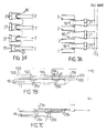
- Fig 7A shows connector assemblies 27 in place between the packages, establishing contact between adjacent packages.
- the contact is established by means of the two horizontal rows of resilient contact springs 23 provided in each connector 7.
- Some of the contact springs 23b are in electrical contact with a power bus 13, e.g. by means of an electrical connection provided at the back of each connector 7, as well as in direct ohmic contact with the power package pads 20b, e.g. through holes provided in the flat cable.
- the other contact springs 23a could be electrically isolated and are establishing electrical contact between the flat cable contact pads 102 and the signal package pads 20a by pressing the flat cable 10 against the package 2.
- a flat cable 10 is shown in place on top of a package 2.
- the shown flat cable 10 includes one data wire layer 105 provided with a data wire 106 and one contact pad layer 100 provided with one electrically conducting contact pad 102.
- the shown package 2 includes two conductors 19 and two package pads 20, one power package pad 20b and one data package pad 20a.
- the hole provided in the flat cable 10 in Fig 7B allows a contact spring 23 (not shown in Fig 7B) to contact the power package pad 20b. This is shown in Fig 7C, in which a power supply contact spring 23b is in contact with the power package pad 20b.
- the backplanes could hold the power busses 13 and provide mechanical support to the cage assembly.
- This appendix shows a list of parts or details of parts, each provided with a corresponding reference-numeral, the list being ordered in reference-numeral order.
Landscapes
- Engineering & Computer Science (AREA)
- Microelectronics & Electronic Packaging (AREA)
- Physics & Mathematics (AREA)
- Thermal Sciences (AREA)
- Cooling Or The Like Of Electrical Apparatus (AREA)
- Details Of Connecting Devices For Male And Female Coupling (AREA)
- Coupling Device And Connection With Printed Circuit (AREA)
Applications Claiming Priority (3)
| Application Number | Priority Date | Filing Date | Title |
|---|---|---|---|
| SE9100596A SE9100596D0 (sv) | 1991-03-01 | 1991-03-01 | Magasin foer stora vlsi-kapslar |
| SE9100596 | 1991-03-01 | ||
| PCT/SE1992/000117 WO1992016092A1 (en) | 1991-03-01 | 1992-02-26 | A housing for electric circuitry packages and a method for assembling such a housing |
Publications (2)
| Publication Number | Publication Date |
|---|---|
| EP0573533A1 EP0573533A1 (en) | 1993-12-15 |
| EP0573533B1 true EP0573533B1 (en) | 1996-06-12 |
Family
ID=20382021
Family Applications (1)
| Application Number | Title | Priority Date | Filing Date |
|---|---|---|---|
| EP92906174A Expired - Lifetime EP0573533B1 (en) | 1991-03-01 | 1992-02-26 | A housing for electric circuitry packages |
Country Status (11)
| Country | Link |
|---|---|
| US (1) | US5404270A (Sortimente) |
| EP (1) | EP0573533B1 (Sortimente) |
| JP (1) | JPH06504879A (Sortimente) |
| CN (1) | CN1064767A (Sortimente) |
| AU (1) | AU1336392A (Sortimente) |
| DE (1) | DE69211538T2 (Sortimente) |
| IL (1) | IL101108A0 (Sortimente) |
| SE (1) | SE9100596D0 (Sortimente) |
| TW (1) | TW222365B (Sortimente) |
| WO (1) | WO1992016092A1 (Sortimente) |
| ZA (1) | ZA921529B (Sortimente) |
Families Citing this family (15)
| Publication number | Priority date | Publication date | Assignee | Title |
|---|---|---|---|---|
| SE9604705L (sv) | 1996-12-20 | 1998-06-21 | Ericsson Telefon Ab L M | Förfarande och medel för att arrangera värmeöverföring |
| US5945746A (en) * | 1997-08-21 | 1999-08-31 | Tracewell Power, Inc. | Power supply and power supply/backplane assembly and system |
| US6169247B1 (en) * | 1998-06-11 | 2001-01-02 | Lucent Technologies Inc. | Enclosure for electronic components |
| US6142090A (en) * | 1998-10-07 | 2000-11-07 | Electric Boat Corporation | Power converter arrangement for integration into a ship structure |
| US7373268B1 (en) * | 2003-07-30 | 2008-05-13 | Hewlett-Packard Development Company, L.P. | Method and system for dynamically controlling cooling resources in a data center |
| WO2009032144A2 (en) * | 2007-08-28 | 2009-03-12 | General Dynamics Advanced Information Systems, Inc. | System and method for interconnecting circuit boards |
| US20090120607A1 (en) * | 2007-11-08 | 2009-05-14 | Cheon Peter | Cooler for spatially confined cooling |
| JP5556972B1 (ja) * | 2012-07-30 | 2014-07-23 | 株式会社村田製作所 | フラットケーブル |
| JP6022307B2 (ja) * | 2012-11-02 | 2016-11-09 | 日立オートモティブシステムズ株式会社 | 電子制御装置 |
| DE102017223476A1 (de) | 2017-12-20 | 2019-06-27 | Elringklinger Ag | Kühlmodul für einen Zellstapel, Zellstapel, Batterievorrichtung und Verfahren zum Kühlen von Zellen |
| DE102017223474A1 (de) * | 2017-12-20 | 2019-06-27 | Elringklinger Ag | Kühlmodul für einen Zellstapel, Zellstapel, Batterievorrichtung und Verfahren zum Kühlen von Zellen |
| DE102017223479A1 (de) * | 2017-12-20 | 2019-06-27 | Elringklinger Ag | Kühlmodul für einen Zellstapel, Zellstapel, Batterievorrichtung und Verfahren zum Kühlen von Zellen |
| US10582645B1 (en) * | 2018-09-28 | 2020-03-03 | Hewlett Packard Enterprise Development Lp | Cooling apparatus for electronic components |
| CN109411428B (zh) * | 2018-10-10 | 2020-10-27 | 广东高普达集团股份有限公司 | 一种芯片的高效散热封装金属壳 |
| CN113015394A (zh) * | 2021-03-02 | 2021-06-22 | 豪业(广州)五金有限公司 | 一种用于信号基站机房的节能型日常维护装置 |
Family Cites Families (25)
| Publication number | Priority date | Publication date | Assignee | Title |
|---|---|---|---|---|
| AT245699B (de) * | 1961-06-06 | 1966-03-10 | Hermsdorf Keramik Veb | Modulbaustein |
| DE1440835A1 (de) * | 1963-06-29 | 1969-10-09 | Bbc Brown Boveri & Cie | Linschiebbarer Geraeterahmen zur Aufnahme elektrischer Anlageteile,vorzugsweise fuerelektronische Anlagen |
| FR1433088A (fr) * | 1965-05-05 | 1966-03-25 | Ibm | Procédé pour fabriquer des montages à couches multiples de circuits imprimés |
| US3492538A (en) * | 1967-09-07 | 1970-01-27 | Thomas & Betts Corp | Removable stack interconnection system |
| US3639891A (en) * | 1969-12-15 | 1972-02-01 | Itt | Termination of flat cables |
| GB1295138A (Sortimente) * | 1970-05-30 | 1972-11-01 | ||
| DE2320202A1 (de) * | 1973-04-19 | 1974-11-07 | Siemens Ag | Anordnung zur wechselseitigen elektrischen verbindung einer mehrzahl von bauteiletraegern (z.b. von gedruckten leiterplatten) |
| US4019798A (en) * | 1976-03-24 | 1977-04-26 | Owens-Illinois, Inc. | Flexible electrical circuit connections |
| US4116516A (en) * | 1977-06-24 | 1978-09-26 | Gte Sylvania Incorporated | Multiple layered connector |
| US4237546A (en) * | 1979-01-31 | 1980-12-02 | Technology Marketing, Inc. | Multi-layered back plane for a computer system |
| CA1115368A (en) * | 1979-06-04 | 1981-12-29 | Ralph D. Whaley | Multi-conductor flat cable connector |
| GB2123216B (en) * | 1982-06-19 | 1985-12-18 | Ferranti Plc | Electrical circuit assemblies |
| DE3435836A1 (de) * | 1984-09-28 | 1986-04-17 | Preh, Elektrofeinmechanische Werke Jakob Preh Nachf. Gmbh & Co, 8740 Bad Neustadt | Anschlusseinrichtung einer schaltungsfolie |
| US4771366A (en) * | 1987-07-06 | 1988-09-13 | International Business Machines Corporation | Ceramic card assembly having enhanced power distribution and cooling |
| CA1306795C (en) * | 1987-09-25 | 1992-08-25 | Minnesota Mining And Manufacturing Company | Thermal transfer bag |
| US4997032A (en) * | 1987-09-25 | 1991-03-05 | Minnesota Mining And Manufacturing Company | Thermal transfer bag |
| US4938279A (en) * | 1988-02-05 | 1990-07-03 | Hughes Aircraft Company | Flexible membrane heat sink |
| US4956746A (en) * | 1989-03-29 | 1990-09-11 | Hughes Aircraft Company | Stacked wafer electronic package |
| US5007478A (en) * | 1989-05-26 | 1991-04-16 | University Of Miami | Microencapsulated phase change material slurry heat sinks |
| JPH0330399A (ja) * | 1989-06-27 | 1991-02-08 | Mitsubishi Electric Corp | 電子冷却装置 |
| US5006924A (en) * | 1989-12-29 | 1991-04-09 | International Business Machines Corporation | Heat sink for utilization with high density integrated circuit substrates |
| US5000256A (en) * | 1990-07-20 | 1991-03-19 | Minnesota Mining And Manufacturing Company | Heat transfer bag with thermal via |
| US5245508A (en) * | 1990-08-21 | 1993-09-14 | International Business Machines Corporation | Close card cooling method |
| US5131859A (en) * | 1991-03-08 | 1992-07-21 | Cray Research, Inc. | Quick disconnect system for circuit board modules |
| US5270902A (en) * | 1992-12-16 | 1993-12-14 | International Business Machines Corporation | Heat transfer device for use with a heat sink in removing thermal energy from an integrated circuit chip |
-
1991
- 1991-03-01 SE SE9100596A patent/SE9100596D0/xx unknown
-
1992
- 1992-02-26 AU AU13363/92A patent/AU1336392A/en not_active Abandoned
- 1992-02-26 DE DE69211538T patent/DE69211538T2/de not_active Expired - Fee Related
- 1992-02-26 JP JP4506111A patent/JPH06504879A/ja active Pending
- 1992-02-26 EP EP92906174A patent/EP0573533B1/en not_active Expired - Lifetime
- 1992-02-26 WO PCT/SE1992/000117 patent/WO1992016092A1/en not_active Ceased
- 1992-02-28 TW TW081101496A patent/TW222365B/zh active
- 1992-02-28 IL IL101108A patent/IL101108A0/xx unknown
- 1992-02-28 ZA ZA921529A patent/ZA921529B/xx unknown
- 1992-02-29 CN CN92101206A patent/CN1064767A/zh active Pending
-
1993
- 1993-11-03 US US08/145,315 patent/US5404270A/en not_active Expired - Fee Related
Also Published As
| Publication number | Publication date |
|---|---|
| CN1064767A (zh) | 1992-09-23 |
| EP0573533A1 (en) | 1993-12-15 |
| DE69211538D1 (de) | 1996-07-18 |
| SE9100596D0 (sv) | 1991-03-01 |
| US5404270A (en) | 1995-04-04 |
| IL101108A0 (en) | 1992-11-15 |
| DE69211538T2 (de) | 1997-01-09 |
| TW222365B (Sortimente) | 1994-04-11 |
| WO1992016092A1 (en) | 1992-09-17 |
| ZA921529B (en) | 1993-08-30 |
| AU1336392A (en) | 1992-10-06 |
| JPH06504879A (ja) | 1994-06-02 |
Similar Documents
| Publication | Publication Date | Title |
|---|---|---|
| EP0573533B1 (en) | A housing for electric circuitry packages | |
| US10734307B2 (en) | Composite heat sink structures | |
| US7068515B2 (en) | Multi-chip module with stacked redundant power | |
| US7791889B2 (en) | Redundant power beneath circuit board | |
| US7499281B2 (en) | Multi-chip module with power system | |
| RU2133523C1 (ru) | Трехмерный электронный модуль | |
| EP0555659B1 (en) | Multi-chip Module | |
| US5014161A (en) | System for detachably mounting semiconductors on conductor substrate | |
| US7254027B2 (en) | Processor module for system board | |
| JP2597461B2 (ja) | コネクタおよびその方法 | |
| CA1270963A (en) | Stacked circuit cards and guided vehicle configurations | |
| US7072185B1 (en) | Electronic module for system board with pass-thru holes | |
| US4104700A (en) | Heat pipe cooling for semiconductor device packaging system | |
| US7280365B2 (en) | Multi-processor module with redundant power | |
| US20050219825A1 (en) | ATCA integrated heatsink and core power distribution mechanism | |
| US7327569B2 (en) | Processor module with thermal dissipation device | |
| US6667885B2 (en) | Attachment of a single heat dissipation device to multiple components with vibration isolation | |
| US5343359A (en) | Apparatus for cooling daughter boards | |
| US7064955B2 (en) | Redundant power for processor circuit board | |
| US6195257B1 (en) | Apparatus and method of adapting a rectifier module to enhance cooling | |
| US3518493A (en) | Arrangement for mounting and connecting microelectronic circuits | |
| US6721188B1 (en) | Power supply for low profile equipment housing | |
| US7348495B2 (en) | Uniform force hydrostatic bolster plate | |
| US20020189089A1 (en) | Mounting electrical devices to circuit boards |
Legal Events
| Date | Code | Title | Description |
|---|---|---|---|
| PUAI | Public reference made under article 153(3) epc to a published international application that has entered the european phase |
Free format text: ORIGINAL CODE: 0009012 |
|
| AK | Designated contracting states |
Kind code of ref document: A1 Designated state(s): DE FR GB SE |
|
| 17P | Request for examination filed |
Effective date: 19930823 |
|
| 17Q | First examination report despatched |
Effective date: 19940412 |
|
| RAP1 | Party data changed (applicant data changed or rights of an application transferred) |
Owner name: PILED ELECTRONICS I PARTILLE AKTIEBOLAG |
|
| GRAA | (expected) grant |
Free format text: ORIGINAL CODE: 0009210 |
|
| AK | Designated contracting states |
Kind code of ref document: B1 Designated state(s): DE FR GB SE |
|
| REF | Corresponds to: |
Ref document number: 69211538 Country of ref document: DE Date of ref document: 19960718 |
|
| GRAH | Despatch of communication of intention to grant a patent |
Free format text: ORIGINAL CODE: EPIDOS IGRA |
|
| PG25 | Lapsed in a contracting state [announced via postgrant information from national office to epo] |
Ref country code: SE Effective date: 19960912 |
|
| ET | Fr: translation filed | ||
| PLBE | No opposition filed within time limit |
Free format text: ORIGINAL CODE: 0009261 |
|
| STAA | Information on the status of an ep patent application or granted ep patent |
Free format text: STATUS: NO OPPOSITION FILED WITHIN TIME LIMIT |
|
| 26N | No opposition filed | ||
| PGFP | Annual fee paid to national office [announced via postgrant information from national office to epo] |
Ref country code: GB Payment date: 19980220 Year of fee payment: 7 |
|
| PGFP | Annual fee paid to national office [announced via postgrant information from national office to epo] |
Ref country code: DE Payment date: 19980225 Year of fee payment: 7 |
|
| PGFP | Annual fee paid to national office [announced via postgrant information from national office to epo] |
Ref country code: FR Payment date: 19980302 Year of fee payment: 7 |
|
| PG25 | Lapsed in a contracting state [announced via postgrant information from national office to epo] |
Ref country code: GB Free format text: LAPSE BECAUSE OF NON-PAYMENT OF DUE FEES Effective date: 19990226 |
|
| GBPC | Gb: european patent ceased through non-payment of renewal fee |
Effective date: 19990226 |
|
| PG25 | Lapsed in a contracting state [announced via postgrant information from national office to epo] |
Ref country code: FR Free format text: LAPSE BECAUSE OF NON-PAYMENT OF DUE FEES Effective date: 19991029 |
|
| PG25 | Lapsed in a contracting state [announced via postgrant information from national office to epo] |
Ref country code: DE Free format text: LAPSE BECAUSE OF NON-PAYMENT OF DUE FEES Effective date: 19991201 |
|
| REG | Reference to a national code |
Ref country code: FR Ref legal event code: ST |