EP0573388B1 - Generating device for characteristic signals of the displacement of a closure means - Google Patents
Generating device for characteristic signals of the displacement of a closure means Download PDFInfo
- Publication number
- EP0573388B1 EP0573388B1 EP93810369A EP93810369A EP0573388B1 EP 0573388 B1 EP0573388 B1 EP 0573388B1 EP 93810369 A EP93810369 A EP 93810369A EP 93810369 A EP93810369 A EP 93810369A EP 0573388 B1 EP0573388 B1 EP 0573388B1
- Authority
- EP
- European Patent Office
- Prior art keywords
- closing
- signal
- ascent
- descent
- program
- Prior art date
- Legal status (The legal status is an assumption and is not a legal conclusion. Google has not performed a legal analysis and makes no representation as to the accuracy of the status listed.)
- Expired - Lifetime
Links
Images


Classifications
-
- E—FIXED CONSTRUCTIONS
- E06—DOORS, WINDOWS, SHUTTERS, OR ROLLER BLINDS IN GENERAL; LADDERS
- E06B—FIXED OR MOVABLE CLOSURES FOR OPENINGS IN BUILDINGS, VEHICLES, FENCES OR LIKE ENCLOSURES IN GENERAL, e.g. DOORS, WINDOWS, BLINDS, GATES
- E06B9/00—Screening or protective devices for wall or similar openings, with or without operating or securing mechanisms; Closures of similar construction
- E06B9/56—Operating, guiding or securing devices or arrangements for roll-type closures; Spring drums; Tape drums; Counterweighting arrangements therefor
- E06B9/80—Safety measures against dropping or unauthorised opening; Braking or immobilising devices; Devices for limiting unrolling
- E06B9/82—Safety measures against dropping or unauthorised opening; Braking or immobilising devices; Devices for limiting unrolling automatic
- E06B9/86—Safety measures against dropping or unauthorised opening; Braking or immobilising devices; Devices for limiting unrolling automatic against unauthorised opening
-
- E—FIXED CONSTRUCTIONS
- E06—DOORS, WINDOWS, SHUTTERS, OR ROLLER BLINDS IN GENERAL; LADDERS
- E06B—FIXED OR MOVABLE CLOSURES FOR OPENINGS IN BUILDINGS, VEHICLES, FENCES OR LIKE ENCLOSURES IN GENERAL, e.g. DOORS, WINDOWS, BLINDS, GATES
- E06B9/00—Screening or protective devices for wall or similar openings, with or without operating or securing mechanisms; Closures of similar construction
- E06B9/56—Operating, guiding or securing devices or arrangements for roll-type closures; Spring drums; Tape drums; Counterweighting arrangements therefor
- E06B9/80—Safety measures against dropping or unauthorised opening; Braking or immobilising devices; Devices for limiting unrolling
- E06B9/82—Safety measures against dropping or unauthorised opening; Braking or immobilising devices; Devices for limiting unrolling automatic
- E06B9/88—Safety measures against dropping or unauthorised opening; Braking or immobilising devices; Devices for limiting unrolling automatic for limiting unrolling
-
- E—FIXED CONSTRUCTIONS
- E06—DOORS, WINDOWS, SHUTTERS, OR ROLLER BLINDS IN GENERAL; LADDERS
- E06B—FIXED OR MOVABLE CLOSURES FOR OPENINGS IN BUILDINGS, VEHICLES, FENCES OR LIKE ENCLOSURES IN GENERAL, e.g. DOORS, WINDOWS, BLINDS, GATES
- E06B9/00—Screening or protective devices for wall or similar openings, with or without operating or securing mechanisms; Closures of similar construction
- E06B9/56—Operating, guiding or securing devices or arrangements for roll-type closures; Spring drums; Tape drums; Counterweighting arrangements therefor
- E06B9/68—Operating devices or mechanisms, e.g. with electric drive
- E06B2009/6809—Control
- E06B2009/6818—Control using sensors
- E06B2009/6836—Control using sensors sensing obstacle
-
- E—FIXED CONSTRUCTIONS
- E06—DOORS, WINDOWS, SHUTTERS, OR ROLLER BLINDS IN GENERAL; LADDERS
- E06B—FIXED OR MOVABLE CLOSURES FOR OPENINGS IN BUILDINGS, VEHICLES, FENCES OR LIKE ENCLOSURES IN GENERAL, e.g. DOORS, WINDOWS, BLINDS, GATES
- E06B9/00—Screening or protective devices for wall or similar openings, with or without operating or securing mechanisms; Closures of similar construction
- E06B9/56—Operating, guiding or securing devices or arrangements for roll-type closures; Spring drums; Tape drums; Counterweighting arrangements therefor
- E06B9/68—Operating devices or mechanisms, e.g. with electric drive
- E06B2009/6809—Control
- E06B2009/6818—Control using sensors
- E06B2009/6845—Control using sensors sensing position
Definitions
- a signal generator device associated with a motorized roller shutter is described in patent FR 2 657 646.
- This generator comprises a pulley mounted on the winding axis of the roller shutter and on which is wound a flexible element whose other end is connected to the end of the shutter, so that the unwinding of the shutter drives the pulley whose axis is mechanically connected to a signal generator, for example a synchronous motor.
- the generator arranged laterally on the winding axis, therefore requires a space which is not always available in a window frame or a door frame.
- the flexible element connecting the generator pulley to the final bar of the roller shutter is unattractive and this flexible element can be accidentally hung or damaged due to its unprotected passage, such an incident being liable to seriously disturb the operation of the roller shutter.
- the present invention aims to overcome these drawbacks.
- the signal generator device is characterized in that it comprises a wiper secured to the closure means, a rigid rigid element capable of being driven in vibration by the wiper and extending over at least the length of the stroke of the closure means so that the wiper rubs on the rigid element during movement of the closure means, and a vibration sensor rigidly mounted on the rigid element and delivering a signal characteristic of these vibrations.
- the closing means generally comprise guide means in the form of a slide, so that the wiper can move in the slide while being hidden and perfectly protected.
- the rigid vibrating element can be constituted by the slide itself or by the guide slide of a tilting or side-moving door or by an element attached to this slide or this slide.
- the invention also relates to a motorized closure equipped with at least one signal generator device according to the invention, this closure being characterized in that it further comprises electronic means for processing the signal emitted by the vibration sensor and means for controlling the drive motor or motors of the closing means as a function of the orders received from the signal processing means.
- the control means can ensure both the closure stop, when the latter encounters an obstacle, as well as the triggering of an alarm in the event of an attempt intrusion, as well as the closure stop at the end of the stroke and / or in intermediate positions, using a toothed or grooved vibrating element allowing to obtain a vibration having periodic variations corresponding to its teeth or grooves and therefore characteristics of the closing position.
- Figure 1 is a sectional view of a roller shutter equipped with a generator according to the invention.
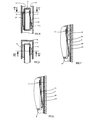
- Figure 4 shows the detail, in vertical section along IV-IV of Figure 5, of an exemplary embodiment of the vibrating element and the wiper.
- FIG. 5 is a sectional view along V-V of FIG. 4.
- FIGS 6 and 7 show two other embodiments of the vibrating element.
- FIG. 8 represents the diagram of the signal processing means and of the means for controlling the rolling stock shown in FIG. 1.
- FIG. 9 represents a first embodiment of the reference signal generator.
- FIG. 10 shows a simplified embodiment of the reference signal generator.
- FIG. 11 represents the main program of the control means.
- FIG. 12 represents a variant of a sub-program for controlling the shutter shutter.
- FIG. 14 represents the decoding circuit of an alternative embodiment with two sensors.
- FIG. 16 represents a variant of the main program for the case of transmission of signals with periodic variations.
- Figure 17 shows the variation counting routine.
- Figure 18 shows the alarm routine.
- FIG. 19 represents a modification of the program of FIG. 16 making it possible to obtain intermediate stop positions.
- FIG. 20 represents the counting subroutine of the variant represented in FIG. 19.
- the vibration sensor can be of the accelerometer or piezoelectric or ferroelectric shock detector type, of micro-machined silicon with integrated processing electronics, for example a sensor sold by MURATA under the trade name PKS-4A.
- the signals emitted by the sensor 7 are processed by a control device 13 controlling the motor of the winding axis 4.
- the installation is completed by a remote control 14, connected galvanically or not to the control electronics 13 and comprising keys for controlling the raising, lowering and stopping of the shutter.
- FIG. 3 represents an alternative embodiment of FIG. 2, in which the stop 6 is removed and the vibrating element 9 is shorter.
- the upper position of the shutter is reached when the wiper leaves the vibrating element 9. This execution allows the shutter to stop smoothly, without sudden pulling. She is particularly advantageous in the case of fragile roller shutters.
- FIGS 4 and 5 show, in more detail, an embodiment and mounting of the wiper 11. It is fixed by riveting, welding or clipping at a point 17 inside the last tubular blade 8 of the shutter rolling and passes through this blade through a slot 18.
- the wiper 11 has a curved end 11a in contact with the vibrating element formed here by the slide 3 itself.
- the vibrating element consists of a rough blade 19 fixed to the slide by means of an adhesive 20.
- the rough blade 19 is replaced by a blade 21 having a serrated profile 22.
- This profile could also be serrated.
- Such a profile makes it possible to obtain a periodic variation in the amplitude of the vibrations, each variation corresponding to a tooth or a niche.
- the counting of these variations makes it possible to determine the position of the wiper, that is to say the position of the roller shutter.
- the control device 13 is shown diagrammatically in FIG. 8. It consists of processing electronics 23 and control electronics 24 for controlling the motor 25.
- the comparator 28 has the function of comparing the value of the signal received from the amplifier-demodulator 26 to that received from the reference generator 27 and of delivering a logic signal (0 or 1) according to the relative level of the compared values. In the particular case, the comparator 28 delivers the signal 1 when the value of the signal picked up is greater than the reference value.
- the microprocessor 29 further includes a fourth DPI input (intermediate position request), a position counter 291 and a reaction time counter 292, a memory 294 for storing the alarm reaction time or the minimum position variation for triggering an alarm and a memory 295 for storing the value of the position counter.
- a fourth DPI input intermediate position request
- a position counter 291 for storing the alarm reaction time or the minimum position variation for triggering an alarm
- a memory 295 for storing the value of the position counter.
- the control device 13 further comprises a stabilized supply 32 for supplying various components.
- the execution mode corresponding to the program represented in FIG. 11 includes two end of travel or obstacle indicators, up and down FCM and FCD positioned high by the stop subroutines, respectively in the direction of ascent (M) and descent (D) and reset to zero when moving in the opposite direction.
- This embodiment therefore makes it possible to stop at the end of the race at a high, low stopping point and in the event of obstacles, by detection of the interruption of the vibrations, as well as the detection of an intrusion attempt by appearance. vibrations.
- the alarm subroutine could be deleted.
- the Up and Down stop subroutines of figure 11 are replaced by the subroutine according to figure 12 and the microprocessor includes a memory 293 storing the stop reaction time value and a stop reaction time counter 292.
- the instruction 33 increments the stop reaction time counter 292.
- the following instruction is a test instruction 34 which compares the counted value with the stored value. If the counted value is greater than the memorized value, then only the SM and SD outputs are set to zero by the following instruction and the program loops. Simultaneously, instruction 35 resets counter 292 to 0.
- the program loops without issuing a stop command.
- instruction 36 increments counter 292 and instruction 37 compares the counted value with the value stored in memory 294. If the counted value is greater than the stored value, the SA output goes to 1 and a alarm is triggered. Simultaneously, instruction 38 resets the counter to 292 at 0.
- This embodiment makes it possible to avoid stopping or triggering alarms resulting from false faults, such as those caused by shocks, hard points in the slide, fugitive obstacles.
- the safety-stop device which has just been described leads to stopping the descent in the non-stacked blade position (so-called "openwork” position if the wiper has been arranged on the lower blade of the closure (blade 8).
- Another interesting embodiment consists in using two vibration sensors, one per slide. This embodiment makes it possible to define an intermediate position and / or several operating zones.
- the intermediate position here corresponds to the "openwork" position described above.
- a first wiper A is disposed on the lower blade 8 of the shutter, on the side of a first slide 3A (or of the corresponding vibration element).
- the second wiper B is placed on the side of the slide 3B (or of the corresponding vibration element) and it is placed on the blade penetrating the slide 3B (or coming into contact with the corresponding vibration element) when the flap arrives in the intermediate position.
- FIG. 14 represents the decoding of the four usable zones.
- SLA and SLB represent the signals delivered by each of the sensors in the presence of vibrations. The algorithms for exploiting this information are within the reach of those skilled in the art.
- FIG. 15 represents a particularly simple embodiment of the logic of the control device 13 indicated by the control algorithms of FIGS. 11 and 12 (alarm function excluded).
- This embodiment uses wired logic and requires only three current integrated circuits (for example TL 084, MC 14538 B, 74 C 74) possibly replaceable by a single circuit of the ASIC type.
- a unipolar established power supply 71 supplies a supply voltage + Vcc to the entire assembly. This voltage is divided by two to allow, at the output of a follower 72, a potential reference used as virtual ground for the analog part of the circuit.
- the piezoelectric detector 7 sees its output signal amplified by two operational amplifiers 74 and 75, with elimination of any continuous components.
- the amplified signal is applied to the input (+) of an operational amplifier 76 which is used in comparator mode.
- the output levels of comparator 76 then correspond to the saturation voltages of the operational amplifier and are close enough to + Vcc and 0 to attack CMOS type logic.
- Each vibration detected and amplified causes the output of the comparator 76 (equivalent to the signal SL of the programmed execution) to go to the "high" state as long as the amplified level is greater than a reference voltage applied to the input ( -) of comparator 76 by a resistive divider bridge.
- Amplifiers 72, 73, 74, 75, 76 belong to the same integrated circuit (for example TL084).
- the output of comparator 76 is applied to a monostable 77 (retriggerable one shot, for example MC 14538 B) whose output Q * goes to the low state for a fixed duration T when the input A undergoes a transition from the "low” state to the "high” state.
- This duration T is always counted from the last upward transition of the input if several pulses are applied to it.
- the duration T is chosen so as to be greater than the maximum time separating two pulses during the movement of the wiper on the vibration element.
- the output Q * therefore returns to the high state only if the vibrations disappear for a duration greater than T.
- two flip-flops 78 and 79 record the state present on the Data input. This state is taken from the collectors of two transistors 80 and 81. One or the other of the transistors is conductive in the event of movement. In the Up SM direction, the transistor 80 is conductive. In the SD down direction, transistor 81 is conductive. The collector of the conducting transistor is in the "low” state while the collector of the blocked transistor is in the "high” state.
- the circuit further comprises a switch 84 with three positions: DD, STOP (intermediate position) and DM controlled by the remote control 14.
- transil diodes 85 and 86 designate transil diodes or other protection devices intended to avoid induced variations in potential of high amplitude on the emitter of a transistor not connected to ground by the switch 84.
- the senor 7 is designed to emit at least one signal of higher value on the passage of each tooth or slot and the reference value supplied by the reference generator 27 of the processing electronics 23 is fixed so as to that the processing electronics does not deliver a 0 or 1 signal on the SL output until each reception of this higher value signal.
- These signals are counted by the position counter 291 of the microprocessor 29 and the number of signals transmitted is stored in memory 295.
- the program according to FIG. 16 comprises the following instructions: a request and initialization (DI) instruction 39, an instruction 40 for scanning the DD input (descent request), an instruction 41 for resetting the position counter 291 to zero, a instruction 42 for initializing a counting subroutine, an instruction 43 for copying the value counted by the counter 291 into the position memory 295, an instruction 44 for reading the position counter 291, an instruction 45 for comparing from the counted value to the value stored in 295, an instruction 46 for initializing the counting subroutine, an instruction 47 for comparing the counted value with the stored value, an instruction 48 for initializing a subroutine ascent, an instruction 49 for testing the value counted by the position counter 291 and an instruction 50 for initializing the counting subroutine. Instructions 42, 46 and 50 initialize the same counting routine.
- DI request and initialization
- Instruction 45 tests whether the value counted is greater than or equal to the value stored in the position memory 295.
- Instruction 48 allows the shutter to be raised if it has encountered an obstacle.
- Instruction 49 tests whether the counted value is less than or equal to 0.
- This embodiment makes it possible, in the case of the descent of the roller shutter, to distinguish the arrival in the low position (closed position) from the arrival on an obstacle and, in this case, to activate the subroutine of ascent 48 to clear the obstacle.
- the counting and alarm subroutines may or may not include instructions intended to prevent the sending of a stop or alarm order, respectively, before the reception of a certain number of signals.
- the counting and alarm subroutines are developed in Figures 17 and 18 respectively.
- the alarm subroutine is optional.
- the alarm subroutine represented in FIG. 18 includes an instruction 55 for incrementing an alarm reaction time counter, an instruction 56 testing whether the reaction time counted is greater than the stored time, an instruction 57 for resetting the alarm reaction time counter, an instruction 58 for incrementing a counter for variation of the minimum alarm position, an instruction 59 testing whether the value counted by the mini alarm position variation counter is greater than or equal to a value stored in memory 294 and an instruction 60 for resetting the mini alarm position variation counter to zero.
- Instructions 55 and 56 can be deleted if the introduction of a reaction time is dispensed with.
- This embodiment makes it possible, as in the initial embodiment, to avoid stops or alarms resulting from false faults.
- the characteristic position signals obtained by means of a toothed or grooved vibrating element, as described in the previous embodiment, can be used to determine intermediate positions of the roller shutter.
- the program represented in FIG. 16 is supplemented by the subroutines represented in FIGS. 19 and 20.
- the subroutine shown in Figure 19 is an intermediate position request subroutine. It includes an instruction 61 for testing the state of the DPI input (intermediate position request), a test instruction 62 testing whether the value of counted signals is greater than the value stored in the memory for storing the signal number corresponding to an intermediate position, a test instruction 63 testing whether the counted value is less than the stored value and an instruction 64 initializing a DPI counting subroutine (request for intermediate position). Instructions 65 and 66 can be deleted if the introduction of a reaction time is dispensed with.
- DPI 1 (intermediate position request)
- the program continues with the test instruction 62 which tests whether the number of signals counted is greater than the stored number counted from the high position. If the counted value is not greater than the memorized value, the program continues with the test instruction 63. If 63 tests that the counted value is less than the memorized value, which means that the wiper is above from the desired intermediate position, the SD output then changes to 1 and the program continues with the DPI counting routine, as shown in Figure 20.
- instruction 62 tests that the counted value is greater than the stored signal number, this means that the wiper is below the intermediate position.
- the output SM is set to 1 and the instruction 64 ′ calls a DPI counting subroutine analogous to the subroutine represented in FIG. 20, but without the ascent subroutine 67 since there is (already) an order climb.
- This embodiment allows the closure to be automatically stopped in a position located between the extreme positions and is particularly advantageous, for example, for stopping a rolling shutter in the open position, that is to say in a low position in which the shutter blades are not stacked on top of each other.
Landscapes
- Engineering & Computer Science (AREA)
- Structural Engineering (AREA)
- Architecture (AREA)
- Civil Engineering (AREA)
- Operating, Guiding And Securing Of Roll- Type Closing Members (AREA)
- Paper (AREA)
- Portable Nailing Machines And Staplers (AREA)
- Fuel-Injection Apparatus (AREA)
- Power-Operated Mechanisms For Wings (AREA)
- Eye Examination Apparatus (AREA)
- Input Circuits Of Receivers And Coupling Of Receivers And Audio Equipment (AREA)
- Measurement Of Mechanical Vibrations Or Ultrasonic Waves (AREA)
- Shutters For Cameras (AREA)
- Preliminary Treatment Of Fibers (AREA)
Abstract
Description
La présente invention a pour objet un dispositif générateur de signaux caractéristiques du déplacement d'un moyen de fermeture, tel que volet, enroulable ou non, store ou porte.The present invention relates to a device generating signals characteristic of the movement of a closing means, such as a shutter, rollable or not, blind or door.
De tels générateurs sont utilisés pour la commande et le contrôle du déplacement de moyens de fermeture, en particulier pour la détection d'obstacles, la détection de tentatives d'intrusion et la commande de l'arrêt du moyen de fermeture en fin de course.Such generators are used for commanding and controlling the movement of closing means, in particular for detecting obstacles, detecting intrusion attempts and controlling the stopping of the closing means at the end of the travel.
Un dispositif générateur de signaux associé à un volet roulant motorisé est décrit dans le brevet FR 2 657 646. Ce générateur comprend une poulie montée sur l'axe d'enroulement du volet roulant et sur laquelle est enroulé un élément souple dont l'autre extrémité est reliée à l'extrémité du volet roulant, de telle sorte que le déroulement du volet entraîne la poulie dont l'axe est relié mécaniquement à un générateur de signaux, par exemple un moteur synchrone. Le générateur, disposé latéralement sur l'axe d'enroulement, nécessite donc un espace qui n'est pas toujours disponible dans une embrasure de fenêtre ou un encadrement de porte. D'autre part, l'élément souple reliant la poulie du générateur à la barre finale du volet roulant est peu esthétique et cet élément souple peut être accroché accidentellement ou détérioré en raison de son passage non protégé, un tel incident étant susceptible de perturber sérieusement le fonctionnement du volet roulant.A signal generator device associated with a motorized roller shutter is described in
La présente invention a pour but d'obvier à ces inconvénients.The present invention aims to overcome these drawbacks.
Le dispositif générateur de signaux selon l'invention est caractérisé en ce qu'il comprend un frotteur solidaire du moyen de fermeture, un élément rigide fixe susceptible d'être entraîné en vibrations par le frotteur et s'étendant sur au moins la longueur de la course du moyen de fermeture de manière à ce que le frotteur frotte sur l'élément rigide lors du déplacement du moyen de fermeture, et un capteur de vibrations monté rigidement sur l'élément rigide et délivrant un signal caractéristique de ces vibrations.The signal generator device according to the invention is characterized in that it comprises a wiper secured to the closure means, a rigid rigid element capable of being driven in vibration by the wiper and extending over at least the length of the stroke of the closure means so that the wiper rubs on the rigid element during movement of the closure means, and a vibration sensor rigidly mounted on the rigid element and delivering a signal characteristic of these vibrations.
Les moyens de fermeture comprennent généralement des moyens de guidage en forme de glissière, de telle sorte que le frotteur peut se déplacer dans la glissière en étant caché et parfaitement protégé.The closing means generally comprise guide means in the form of a slide, so that the wiper can move in the slide while being hidden and perfectly protected.
L'élément rigide vibrant peut être constitué par la glissière elle-même ou par la coulisse de guidage d'une porte basculante ou à déplacement latéral ou par un élément rapporté sur cette glissière ou cette coulisse.The rigid vibrating element can be constituted by the slide itself or by the guide slide of a tilting or side-moving door or by an element attached to this slide or this slide.
L'invention a également pour objet une fermeture motorisée équipée d'au moins un dispositif générateur de signaux selon l'invention, cette fermeture étant caractérisée en ce qu'elle comprend en outre des moyens électroniques de traitement du signal émis par le capteur de vibrations et des moyens de commande du ou des moteurs d'entraînement du moyen de fermeture en fonction des ordres reçus des moyens de traitement du signal.The invention also relates to a motorized closure equipped with at least one signal generator device according to the invention, this closure being characterized in that it further comprises electronic means for processing the signal emitted by the vibration sensor and means for controlling the drive motor or motors of the closing means as a function of the orders received from the signal processing means.
Les moyens de commande peuvent assurer aussi bien l'arrêt de la fermeture, lorsque celle-ci rencontre un obstacle, que le déclenchement d'une alarme en cas de tentative d'intrusion, ainsi que l'arrêt de la fermeture en fin course et/ou en des positions intermédiaires, en utilisant un élément vibrant denté ou cannelé permettant d'obtenir une vibration présentant des variations périodiques correspondant à ses dents ou cannelures et par conséquent caractéristiques de la position de la fermeture.The control means can ensure both the closure stop, when the latter encounters an obstacle, as well as the triggering of an alarm in the event of an attempt intrusion, as well as the closure stop at the end of the stroke and / or in intermediate positions, using a toothed or grooved vibrating element allowing to obtain a vibration having periodic variations corresponding to its teeth or grooves and therefore characteristics of the closing position.
Pour la commande d'un volet roulet à lames empilables, il est possible d'obtenir un arrêt en position ajourée et un arrêt en position empilée au moyen de deux frotteurs, dont l'un est situé sur la lame inférieure et l'autre sur la lame pénétrant dans la glissière juste avant que la lame inférieure arrive en butée.When controlling a roller shutter with stackable blades, it is possible to obtain a stop in the open position and a stop in the stacked position by means of two wipers, one of which is located on the lower blade and the other on the blade penetrating the slide just before the lower blade comes to a stop.
L'utilisation de deux capteurs de vibrations, un par glissière, et de deux frotteurs permet de définir une position intermédiaire et/ou plusieurs zones de fonctionnement.The use of two vibration sensors, one per slide, and two wipers makes it possible to define an intermediate position and / or several operating zones.
Le dessin annexé représente, à titre d'exemple, des formes d'exécution de l'invention.The accompanying drawing shows, by way of example, embodiments of the invention.
La figure 1 est une vue en coupe d'un volet roulant équipé d'un générateur selon l'invention.Figure 1 is a sectional view of a roller shutter equipped with a generator according to the invention.
La figure 2 représente un détail de la figure 1.Figure 2 shows a detail of Figure 1.
La figure 3 représente une variante d'exécution de la figure 2.FIG. 3 represents an alternative embodiment of FIG. 2.
La figure 4 représente le détail, en coupe verticale selon IV-IV de la figure 5, d'un exemple d'exécution de l'élément vibrant et du frotteur.Figure 4 shows the detail, in vertical section along IV-IV of Figure 5, of an exemplary embodiment of the vibrating element and the wiper.
La figure 5 est une vue en coupe selon V-V de la figure 4.FIG. 5 is a sectional view along V-V of FIG. 4.
Les figures 6 et 7 représentent deux autres formes d'exécution de l'élément vibrant.Figures 6 and 7 show two other embodiments of the vibrating element.
La figure 8 représente le schéma des moyens de traitement du signal et des moyens de commande du moyen roulant représenté à la figure 1.FIG. 8 represents the diagram of the signal processing means and of the means for controlling the rolling stock shown in FIG. 1.
La figure 9 représente une première forme d'exécution du générateur de signal de référence.FIG. 9 represents a first embodiment of the reference signal generator.
La figure 10 représente une forme d'exécution simplifiée du générateur de signal de référence.FIG. 10 shows a simplified embodiment of the reference signal generator.
La figure 11 représente le programme principal des moyens de commande.FIG. 11 represents the main program of the control means.
La figure 12 représente une variante de sous-programme pour la commande de l'arrêt du volet roulant.FIG. 12 represents a variant of a sub-program for controlling the shutter shutter.
La figure 13 représente une variante de sous-programme pour le déclenchement d'une alarme en cas de tentative d'intrusion.FIG. 13 represents a variant of a subroutine for triggering an alarm in the event of an intrusion attempt.
La figure 14 représente le circuit de décodage d'une variante d'exécution à deux capteurs.FIG. 14 represents the decoding circuit of an alternative embodiment with two sensors.
La figure 15 représente le schéma d'une exécution câblée du dispositif de commande.FIG. 15 represents the diagram of a wired execution of the control device.
La figure 16 représente une variante du programme principal pour le cas d'une émission de signaux à variations périodiques.FIG. 16 represents a variant of the main program for the case of transmission of signals with periodic variations.
La figure 17 représente le sous-programme de comptage des variations.Figure 17 shows the variation counting routine.
La figure 18 représente le sous-programme d'alarme.Figure 18 shows the alarm routine.
La figure 19 représente une modification du programme de la figure 16 permettant d'obtenir des positions d'arrêt intermédiaires.FIG. 19 represents a modification of the program of FIG. 16 making it possible to obtain intermediate stop positions.
La figure 20 représente le sous-programme de comptage de la variante représentée à la figure 19.FIG. 20 represents the counting subroutine of the variant represented in FIG. 19.
La figure 1 représente, en coupe verticale, une embrasure de fenêtre 1 dans laquelle est monté un volet roulant 2 guidé dans une paire de glissières 3 et s'enroulant sur un axe d'enroulement 4 monté dans un boîtier 5 et entraîné par un moteur non représenté. Le moteur est à deux enroulements assurant la rotation de l'arbre d'enroulement 4 dans deux sens opposés. Le volet roulant 2 est représenté ici en position totalement déroulée. Sa dernière lame est munie d'une butée de fin de course 6 constituée par un ergot destiné à venir buter contre le haut de l'embrasure 1. La glissière 3 est prolongée par une partie 3a dans le boîtier 5 et à l'extrémité de ce prolongement 3a est fixé rigidement un capteur de vibrations 7. Sur la dernière lame 8 du volet roulant est en outre fixé un frotteur, par exemple une lame en acier dont l'extrémité libre frotte sur l'une des faces intérieures de la glissière dont la surface a été rendue rugueuse ou granuleuse par sablage.Figure 1 shows, in vertical section, a
Lors du déplacement du volet roulant 2, le frottement du frotteur 11 sur la glissière 3 engendre des vibrations qui sont transmises par la glissière au capteur de vibrations 7. Le capteur de vibrations peut être de type accéléromètre ou détecteur de chocs piézo-ou ferro-électriques, de typesilicium micro-usiné à électronique de traitement intégré, par exemple un capteur commercialisé par MURATA sous la dénomination commerciale PKS-4A.When moving the
Les signaux émis par le capteur 7 sont traités par un dispositif de commande 13 commandant le moteur de l'axe d'enroulement 4. L'installation est complétée par une commande à distance 14, reliée galvaniquement ou non à l'électronique de commande 13 et comportant des touches permettant de commander la montée, la descente et l'arrêt du volet roulant.The signals emitted by the
Au lieu de frotter directement sur la glissière, le frotteur peut frotter sur un élément vibrant auxiliaire. Le détail d'un mode d'exécution est représenté à la figure 2. L'élément vibrant est constitué d'une lame d'acier 9 fixée sur l'une des faces intérieures 10 de la glissière 3 et sur laquelle frotte un frotteur 11. La face opposée 12 de la glissière est lisse et la dernière lame 8 est munie d'un patin 15 glissant sur la face 12. Dans le cas de la figure 2, la butée 6 vient buter contre l'embrasure lorsque le volet arrive en position haute, les vibrations cessent et le détecteur 7 détecte l'absence de vibration et commande l'arrêt du moteur.Instead of rubbing directly on the slide, the wiper can rub on an auxiliary vibrating element. The detail of an embodiment is shown in Figure 2. The vibrating element consists of a
La figure 3 représente une variante d'exécution de la figure 2, dans laquelle la butée 6 est supprimée et l'élément vibrant 9 est plus court. La position haute du volet est atteinte lorsque le frotteur quitte l'élément vibrant 9. Cette exécution permet un arrêt du volet en douceur, sans traction brusque. Elle est particulièrement avantageuse dans le cas de volets roulants fragiles.FIG. 3 represents an alternative embodiment of FIG. 2, in which the
Les figures 4 et 5 représentent, plus en détail, un mode d'exécution et de montage du frotteur 11. Celui-ci est fixé par rivetage, soudage ou clipsage en un point 17 à l'intérieur de la dernière lame tubulaire 8 du volet roulant et traverse cette lame à travers une fente 18. Le frotteur 11 présente une extrémité recourbée 11a en contact avec l'élément vibrant constitué ici par la glissière 3 elle-même.Figures 4 and 5 show, in more detail, an embodiment and mounting of the
A la figure 6, l'élément vibrant est constitué d'une lame rugueuse 19 fixée sur la glissière au moyen d'un adhésif 20.In FIG. 6, the vibrating element consists of a
Dans l'exécution selon la figure 7, la lame rugueuse 19 est remplacée par une lame 21 présentant un profil dentelé 22. Ce profil pourrait être également crénelé. Un tel profil permet d'obtenir une variation périodique de l'amplitude des vibrations, chaque variation correspondant à une dent ou un créneau. Le comptage de ces variations permet de déterminer la position du frotteur, c'est-à-dire la position du volet roulant.In the embodiment according to FIG. 7, the
Le principe décrit ci-dessus est applicable à tout moyen de fermeture guidé dans son déplacement, que ce soit par une glissière, un rail ou des gonds.The principle described above is applicable to any closing means guided in its movement, whether by a slide, a rail or hinges.
Le dispositif de commande 13 est représenté schématiquement à la figure 8. Il est constitué d'une électronique de traitement 23 et d'une électronique de commande 24 pour la commande du moteur 25.The
L'électronique de traitement comprend un amplificateur-démodulateur 26, un générateur de référence 27 et un comparateur 28. L'amplificateur-démodulateur 26 a pour fonction de recevoir le signal délivré par le capteur, de l'amplifier, éventuellement de le redresser, de le lisser et de délivrer au comparateur 28 auquel est appliquée, d'autre part, une valeur de référence délivrée par le générateur de référence 27.The processing electronics include an amplifier-
Le générateur de référence 27 peut être constitué par un simple diviseur de tension R1/R2, tel que représenté à la figure 10, délivrant une valeur de tension fixe. Le générateur de référence 27 peut également être conçu pour délivrer une valeur de référence dérivée de la valeur du signal capté, comme représenté à la figure 9. Dans ce cas, il est constitué d'un diviseur de tension R1/R2 en parallèle à un condensateur C, le tout en série avec une résistance R3 auquelle est appliqué le signal capté. Ceci permet de tenir compte de la variation du signal capté dû au vieillissement du capteur ou à toute autre influence et s'adapter automatiquement au niveau de signal correspondant à l'utilisation.The
Le comparateur 28 a pour fonction de comparer la valeur du signal reçu de l'amplificateur-démodulateur 26 à celle reçue du générateur de référence 27 et de délivrer un signal logique (0 ou 1) selon le niveau relatif des valeurs comparées. Dans le cas particulier, le comparateur 28 délivre le signal 1 lorsque la valeur du signal capté est supérieure à la valeur de référence.The
L'électronique de commande 24 comprend un microprocesseur 29 comportant un programme principal (figure 11), des entrées DM (demande de montée), DD (demande de descente), DS (demande de stop), des sorties SM (sortie de montée), SD (sortie de descente), SA (alarme) et une entrée SL (sortie logique) reliée à la sortie du comparateur 28. Sa fonction principale est de faire passer à 0 les sorties SM, SD, SA, lorsque le signal reçu en SL = 0.The
Tel que représenté au dessin, le microprocesseur 29 comporte en outre une quatrième entrée DPI (demande de position intermédiaire), un compteur de position 291 et un compteur de temps de réaction 292, une mémoire 294 pour le stockage du temps de réaction alarme ou de la variation de position minimale pour le déclenchent d'une alarme et une mémoire 295 pour le stockage de la valeur du compteur de position. Ces éléments sont utilisés dans une forme d'exécution plus évoluée de l'invention qui sera décrite en relation avec les figures 16 et 17.As shown in the drawing, the
L'électronique de commande 24 comporte en outre un organe de commutation de puissance 30 relié au réseau PN et à chacun des enroulements sens 1, sens 2 du moteur 25, par des sorties M et D, ainsi qu'à une alarme 31 par une sortie A, et aux sorties SM, SD, SA du microprocesseur 29. Sa fonction est d'interrompre l'alimentation sur M, D et A, lorsque les sorties SM, SD et SA = 0. Le dispositif de commande 13 comporte en outre une alimentation stabilisée 32 pour l'alimentation de différents composants.The
Le mode d'exécution correspondant au programme représenté à la figure 11 comprend deux indicateurs de fin de course ou d'obstacle, en montée et en descente FCM et FCD positionnés à l'état haut par les sous-programmes d'arrêt, respectivement dans le sens de la montée (M) et de la descente (D) et remis à zéro lors d'un mouvement dans le sens inverse.The execution mode corresponding to the program represented in FIG. 11 includes two end of travel or obstacle indicators, up and down FCM and FCD positioned high by the stop subroutines, respectively in the direction of ascent (M) and descent (D) and reset to zero when moving in the opposite direction.
Le fonctionnement selon le programme représenté à la figure 11 est le suivant :The operation according to the program shown in Figure 11 is as follows:
La première instruction effectue la scrutation cyclique des entrées DM, DD, DS, SL du microprocesseur. Si DS = 1 (demande de stop activée), les sorties SM et SD sont mises à zéro et le programme reboucle.The first instruction performs cyclic scanning of the inputs DM, DD, DS, SL of the microprocessor. If DS = 1 (stop request activated), the SM and SD outputs are reset and the program loops.
Si DS = 0 (demande de stop non activée), le programme teste ensuite l'entrée DM (demande de montée). Si DM = 1, l'instruction suivante teste l'indicateur FCM. Si FCM = 1 (volet en position haute), le programme reboucle. Si FCM = 0, l'instruction suivante fait passer la sortie SM à 1, puis appelle le sous-programme d'arrêt qui teste l'entrée SL, c'est-à-dire le signal provenant du capteur 7. Si SL = 1 (présence d'une vibration), l'instruction suivante met l'indicateur de fin de course bas à 0 (FCD = 0) et le programme reboucle sans donner d'ordre de montée, puisque la présence d'un signal de vibrations signifie que le volet n'a pas rencontré d'obstacle ou que son frotteur n'a pas encore quitté l'élément vibrant 19 (figure 3), c'est-à-dire que le volet n'a pas encore atteint sa position haute.If DS = 0 (stop request not activated), the program then tests the DM input (rise request). If DM = 1, the next instruction tests the FCM flag. If FCM = 1 (flap in high position), the program loops. If FCM = 0, the following instruction sets the output SM to 1, then calls the stop subroutine which tests the input SL, that is to say the signal from
Si SL = 0 (absence de vibration), l'instruction suivante fait passer à 0 la sortie SM, l'absence de vibration signifiant que le volet roulant a rencontré un obstacle ou qu'il a atteint son point haut (figures 2 ou 3) et met l'indicateur FCM à 1.If SL = 0 (absence of vibration), the following instruction changes the SM output to 0, the absence of vibration signifying that the roller shutter has encountered an obstacle or that it has reached its highest point (Figures 2 or 3 ) and sets the FCM flag to 1.
Si le test de DM donne 0, le programme teste l'entrée DD. Si DD = 1 (demande de descente), l'instruction suivante teste l'indicateur FCD. Si FCD = 1 (volet déjà en position basse), le programme reboucle sans donner d'ordre d'arrêt. Si FCD = 0, l'instruction suivante met SD = 1 et l'instruction suivante teste la sortie SL. Si SL = 0 (absence de vibration), l'instruction suivante met la sortie SD à 0 (ordre d'arrêt) et l'indicateur FCD à 1. Si SL = 1, l'indicateur FCM est mis à 0 et le programme reboucle sans donner d'ordre de descente.If the DM test gives 0, the program tests the DD input. If DD = 1 (descent request), the following instruction tests the FCD indicator. If FCD = 1 (shutter already in low position), the program loops without giving stop order. If FCD = 0, the next instruction sets SD = 1 and the next instruction tests the SL output. If SL = 0 (no vibration), the following instruction sets the SD output to 0 (stop command) and the FCD flag to 1. If SL = 1, the FCM flag is set to 0 and the program loop without giving a descent order.
Si le test donne DD = 0 (absence de demande de descente), le sous-programme alarme teste l'entrée SL. Si SL = 0, aucune alarme n'est déclenchée, car cela signifie que le volet roulant est immobile et qu'il n'y pas eu tentative d'intrusion. Par contre, si le test donne SL = 1, cela signifie que le volet roulant se déplace en l'absence d'ordre de montée et de descente et la sortie SA passe à 1 ce qui a pour effet de déclencher l'alarme.If the test gives DD = 0 (no lowering request), the alarm subroutine tests the SL input. If SL = 0, no alarm is triggered, as this means that the shutter is stationary and that there has been no attempt at intrusion. On the other hand, if the test gives SL = 1, this means that the shutter moves in the absence of an up and down order and the SA output goes to 1, which has the effect of triggering the alarm.
Cette forme de réalisation permet donc l'arrêt en fin de course en point d'arrêt haut, bas et en cas d'obstacles, par détection de l'interruption des vibrations, ainsi que la détection d'une tentative d'intrusion par apparition de vibrations.This embodiment therefore makes it possible to stop at the end of the race at a high, low stopping point and in the event of obstacles, by detection of the interruption of the vibrations, as well as the detection of an intrusion attempt by appearance. vibrations.
Dans une forme simplifiée, le sous-programme alarme pourrait être supprimé.In a simplified form, the alarm subroutine could be deleted.
Selon une autre forme de réalisation, l'électronique de commande 24 est prévue, de plus, pour tester que le changement de l'ordre logique sur la sortie SL du comparateur demeure un certain temps avant de suspendre la transmission des ordres de déplacement sens 1/sens 2 ou avant de transmettre un ordre d'alarme.According to another embodiment, the
Dans ce cas, les sous-programmes d'arrêt Montée et Descente de la figure 11 sont remplacés par le sous-programme selon figure 12 et le microprocesseur comporte une mémoire 293 stockant la valeur de temps de réaction d'arrêt et un compteur de temps de réaction à l'arrêt 292.In this case, the Up and Down stop subroutines of figure 11 are replaced by the subroutine according to figure 12 and the microprocessor includes a
Selon figure 12, si le test de la sortie logique donne SL = 0, l'instruction 33 incrémente le compteur de temps de réaction arrêt 292. L'instruction suivante est une instruction de test 34 qui compare la valeur comptée à la valeur mémorisée. Si la valeur comptée est supérieure à la valeur mémorisée, alors seulement les sorties SM et SD sont mises à zéro par l'instruction suivante et le programme reboucle. Simultanément, l'instruction 35 remet à 0 le compteur 292.According to FIG. 12, if the test of the logic output gives SL = 0, the
Par contre, aussi longtemps que l'instruction de test 34 teste que la valeur comptée est inférieure à la valeur mémorisée, le programme reboucle sans émission d'ordre d'arrêt.On the other hand, as long as the
Le sous-programme d'alarme de la figure 11 est également complété comme représenté à la figure 13, de manière analogue au sous-programme d'arrêt de la figure 12. Le microprocesseur comporte une mémoire 294 stockant la valeur de temps de réaction d'alarme.The alarm subroutine of FIG. 11 is also completed as shown in FIG. 13, in a similar manner to the shutdown subroutine of FIG. 12. The microprocessor includes a
Si SL = 1, l'instruction 36 incrémente le compteur 292 et l'instruction 37 compare la valeur comptée à la valeur mémorisée dans la mémoire 294. Si la valeur comptée est supérieure à la valeur mémorisée, la sortie SA passe à 1 et une alarme est déclenchée. Simultanément, l'instruction 38 remet le compteur à 292 à 0.If SL = 1,
Cette forme d'exécution permet d'éviter les arrêts ou les déclenchements d'alarme résultant de faux défauts, tels que ceux provoqués par des chocs, des points durs dans la glissière, des obstacles fugitifs.This embodiment makes it possible to avoid stopping or triggering alarms resulting from false faults, such as those caused by shocks, hard points in the slide, fugitive obstacles.
Dans le cas de systèmes de fermeture à lames empilables ou équivalents, le dispositif d'arrêt-sécurité qui vient d'être décrit conduit à l'arrêt de la descente en position lames non empilées (position dite "ajours" si le frotteur a été disposé sur la lame basse de la fermeture (lame 8).In the case of closing systems with stackable blades or equivalent, the safety-stop device which has just been described leads to stopping the descent in the non-stacked blade position (so-called "openwork" position if the wiper has been arranged on the lower blade of the closure (blade 8).
Si l'utilisateur préfère un arrêt en position empilée (totalement fermée), il convient de disposer un deuxième frotteur sur la lame pénétrant dans la glissière 3, au contact de l'élément de vibration, juste avant que la lame basse n'arrive en butée. Cette variante ne nécessite aucune modification des algorithmes et du capteur.If the user prefers a stop in a stacked position (fully closed), it is advisable to have a second wiper on the blade penetrating the
Une autre forme de réalisation intéressante consiste à utiliser deux capteurs de vibration, un par glissière. Cette forme de réalisation permet de définir une position intermédiaire et/ou plusieurs zones de fonctionnement. La position intermédiaire correspond ici à la position "ajours" décrite plus haut.Another interesting embodiment consists in using two vibration sensors, one per slide. This embodiment makes it possible to define an intermediate position and / or several operating zones. The intermediate position here corresponds to the "openwork" position described above.
Un premier frotteur A est disposé sur la lame basse 8 du volet, du côté d'une première glissière 3A (ou de l'élément de vibration correspondant). Le second frotteur B est disposé du côté de la glissière 3B (ou de l'élément de vibration correspondant) et il est placé sur la lame pénétrant dans la glissière 3B (ou entrant en contact de l'élément de vibration correspondant) au moment où le volet arrive en position intermédiaire.A first wiper A is disposed on the
La figure 14 représente le décodage des quatre zones utilisables. SLA et SLB représentent les signaux délivrés par chacun des capteurs en présence de vibrations. Les algorithmes d'exploitation de ces informations sont à la portée de l'homme de l'art.FIG. 14 represents the decoding of the four usable zones. SLA and SLB represent the signals delivered by each of the sensors in the presence of vibrations. The algorithms for exploiting this information are within the reach of those skilled in the art.
Si on a un signal sur SLA et SLB (A=1), cela signifie que la lame inférieure du volet est encore en mouvement alors que l'autre lame est déjà dans les glissières. Cela correspond à une zone très réduite de transition entre l'empilage des lames et l'ouverture.If there is a signal on SLA and SLB (A = 1), this means that the lower blade of the shutter is still moving while the other blade is already in the slides. This corresponds to a very small transition zone between the stacking of the blades and the opening.
Si on a un signal sur SLB seulement alors B=1, ce qui correspond à un mouvement dans la zone d'empilage.If there is a signal on SLB only then B = 1, which corresponds to a movement in the stacking area.
Si on a un signal sur SLA seulement alors C=1, ce qui correspond à un mouvement dans la zone d'ouverture.If there is a signal on SLA only then C = 1, which corresponds to a movement in the opening zone.
Si on n'a aucun signal alors D=1. Dans ce cas, il convient de tester si l'on a un ordre de Montée (SM) ou de Descente (SD).If there is no signal then D = 1. In this case, it is advisable to test whether there is an order of Ascent (SM) or of Descent (SD).
Si SM=1, cela signifie que le volet est en butée haute.If SM = 1, it means that the shutter is in high stop.
Si SD=1, on peut avoir deux situations différentes selon l'état précédent des sorties B et C.If SD = 1, we can have two different situations depending on the previous state of outputs B and C.
Si on avait C=1, D=1 doit être interprété comme la présence d'un obstacle empêchant la descente du volet.If we had C = 1, D = 1 should be interpreted as the presence of an obstacle preventing the descent of the flap.
Si on avait B=1, D=1 signifie que les lames du volet sont complètement empilées et que le volet est donc totalement fermé.If we had B = 1, D = 1 means that the shutter blades are completely stacked and that the shutter is therefore completely closed.
La figure 15 représente un mode de réalisation particulièrement simple de la logique du dispositif de commande 13 indiquée par les algorithmes de commande des figures 11 et 12 (fonction alarme exclue).FIG. 15 represents a particularly simple embodiment of the logic of the
Ce mode de réalisation utilise la logique câblée et ne nécessite que trois circuits intégrés courants (par exemple TL 084, MC 14538 B, 74 C 74) éventuellement remplaçables par un circuit unique de type ASIC. Une alimentation stablisée unipolaire 71 fournit une tension d'alimentation +Vcc à l'ensemble du montage. Cette tension est divisée par deux pour permettre, en sortie d'un suiveur 72, une référence de potentiel utilisée comme masse virtuelle pour la partie analogique du montage.This embodiment uses wired logic and requires only three current integrated circuits (for example TL 084, MC 14538 B, 74 C 74) possibly replaceable by a single circuit of the ASIC type. A unipolar established
Le détecteur piézo-électrique 7 voit son signal de sortie amplifié par deux amplificateurs opérationnels 74 et 75, avec élimination d'éventuelles composantes continues.The
Le signal amplifié est appliqué sur l'entrée (+) d'un amplificateur opérationnel 76 qui est utilisé en mode comparateur.The amplified signal is applied to the input (+) of an
Les niveaux de sortie du comparateur 76 correspondent alors aux tensions de saturation de l'amplificateur opérationnel et sont suffisamment proches de +Vcc et de 0 pour attaquer une logique de type CMOS. Chaque vibration détectée et amplifiée provoque le passage de la sortie du comparateur 76 (équivalente au signal SL de l'exécution programmée) à l'état "haut" tant que le niveau amplifié est supérieur à une tension de référence appliquée à l'entrée (-) du comparateur 76 par un pont diviseur résistif.The output levels of
Les amplificateurs 72, 73, 74, 75, 76 appartiennent à un même circuit intégré (par exemple TL084). La sortie du comparateur 76 est appliquée à un monostable 77 (retriggerable one shot, par exemple MC 14538 B) dont la sortie Q* passe à l'état bas pendant une durée fixe T lorsque l'entrée A subit une transition de l'état "bas" à l'état "haut". Cette durée T est toujours comptée à partir de la dernière transition montante de l'entrée si plusieurs impulsions sont appliquées à celle-ci.
La durée T est choisie de façon à être supérieure au temps maximum séparant deux impulsions lors du mouvement du frotteur sur l'élément de vibration. La sortie Q* ne repasse donc à l'état haut que si les vibrations disparaissent pendant une durée supérieure à T.The duration T is chosen so as to be greater than the maximum time separating two pulses during the movement of the wiper on the vibration element. The output Q * therefore returns to the high state only if the vibrations disappear for a duration greater than T.
Dans ce cas, deux bascules 78 et 79, de type D Flip-Flop (exemple MM 74 C 74) enregistrent l'état présent sur l'entrée Data. Cet état est prélevé sur les collecteurs de deux transistors 80 et 81. L'un ou l'autre des transistors est conducteur en cas de mouvement. Dans le sens Montée SM, le transistor 80 est conducteur. Dans le sens Descente SD, le transistor 81 est conducteur. Le collecteur du transistor conducteur est à l'état "bas" alors que le collecteur du transistor bloqué est à l'état "haut".In this case, two flip-
La bascule 78 ou 79 enregistre donc un état "bas" sur sa sortie Q* si la vibration cesse alors que le sens SM ou SD est activé.The flip-
Cela a pour effet de bloquer la conduction du transistor correspondant.This has the effect of blocking the conduction of the corresponding transistor.
Cet état bloqué se maintient tant que l'autre transistor n'a pas été rendu conducteur, donc tant que l'utilisateur n'a pas donné un ordre de mouvement dans le sens opposé.This blocked state is maintained as long as the other transistor has not been made conductive, therefore as long as the user has not given an order of movement in the opposite direction.
Lorsque l'autre transistor est rendu conducteur, le passage à l'état "bas" de son collecteur provoque une action de remise à l'état "haut" de la sortie Q* de la bascule par action sur son entrée Preset.When the other transistor is made conductive, the passage to the "low" state of its collector causes an action to reset to the "high" state of the output Q * of the flip-flop by action on its Preset input.
Le circuit comprend en outre un commutateur 84 à trois positions : DD, STOP (position intermédiaire) et DM commandé par la commande à distance 14.The circuit further comprises a
85 et 86 désignent des diodes transil ou autres dispositifs de protection destinées à éviter des variations de potentiel induites de forte amplitude sur l'émetteur d'un transistor non relié à la masse par le commutateur 84.85 and 86 designate transil diodes or other protection devices intended to avoid induced variations in potential of high amplitude on the emitter of a transistor not connected to ground by the
On décrira maintenant, en relation avec les figures 16, 17 et 18, une forme d'exécution utilisant un élément vibrant dentelé ou cannelé tel que l'élément vibrant 21 de la figure 7.A description will now be given, in relation to FIGS. 16, 17 and 18, of an embodiment using a serrated or grooved vibrating element such as the vibrating
Dans ce cas, le capteur 7 est prévu pour émettre au moins un signal de plus forte valeur au passage de chaque dent ou créneau et la valeur de référence fournie par le générateur de référence 27 de l'électronique de traitement 23 est fixé de manière à ce que l'électronique de traitement ne délivre sur la sortie SL un signal 0 ou 1 qu'à chaque réception de ce signal de plus forte valeur. Ces signaux sont comptés par le compteur de position 291 du microprocesseur 29 et le nombre de signaux émis est stocké dans la mémoire 295.In this case, the
Le programme correspondant est représenté à la figure 16. En plus des instructions contenues dans le programme de base selon la figure 11, le programme selon la figure 16 comprend les instructions suivantes: une instruction de demande et d'initialisation (DI) 39, une instruction 40 de scrutation de l'entrée DD (demande de descente), une instruction 41 de remise à zéro du compteur de position 291, une instruction 42 d'initialisation d'un sous-programme de comptage, une instruction 43 de recopie de la valeur comptée par le compteur 291 dans la mémoire de position 295, une instruction 44 de lecture du compteur de position 291, une instruction 45 de comparaison de la valeur comptée à la valeur mémorisée dans 295, une instruction 46 d'initialisation du sous-programme de comptage, une instruction 47 de comparaison de la valeur comptée à la valeur mémorisée, une instruction 48 d'initialisation d'un sous-programme de remontée, une instruction 49 de test de la valeur comptée par le compteur de position 291 et une instruction 50 d'initialisation du sous-programme de comptage. Les instructions 42, 46 et 50 initialisent le même sous-programme de comptage.The corresponding program is shown in Figure 16. In addition to the instructions contained in the basic program according to Figure 11, the program according to FIG. 16 comprises the following instructions: a request and initialization (DI)
L'instruction 45 teste si la valeur comptée est supérieure ou égale à la valeur mémorisée dans la mémoire de position 295.
L'instruction de test 47 teste si la valeur comptée est supérieure ou égale à la valeur mémorisée dans la mémoire de position 295.The
L'instruction 48 permet la remontée du volet si celui-ci a rencontré un obstacle.
L'instruction 49 teste si la valeur comptée est inférieure ou égale à 0.
Le programme se déroule comme représenté à la figure 16 et une description plus détaillée est considérée comme superflue.The program runs as shown in Figure 16 and a more detailed description is considered unnecessary.
Cette forme d'exécution permet, dans le cas de la descente du volet roulant, de distinguer l'arrivée en position basse (position fermée) de l'arrivée sur un obstacle et, dans ce cas, d'activer le sous-programme de remontée 48 pour dégager l'obstacle.This embodiment makes it possible, in the case of the descent of the roller shutter, to distinguish the arrival in the low position (closed position) from the arrival on an obstacle and, in this case, to activate the subroutine of
Les sous-programmes de comptage et d'alarme peuvent comprendre ou non des instructions destinées à empêcher l'envoi d'un ordre d'arrêt, respectivement d'alarme, avant la réception d'un certain nombre de signaux. Les sous-programmes de comptage et d'alarme sont développés respectivement aux figures 17 et 18. Le sous-programme d'alarme est facultatif.The counting and alarm subroutines may or may not include instructions intended to prevent the sending of a stop or alarm order, respectively, before the reception of a certain number of signals. The counting and alarm subroutines are developed in Figures 17 and 18 respectively. The alarm subroutine is optional.
Le sous-programme de comptage représenté à la figure 17 comprend une instruction 51 d'incrémentation du compteur de temps de réaction 292, une instruction 52 testant si le temps de réaction compté par le compteur 292 est supérieur au temps de réaction mémorisé dans la mémoire 294, une instruction 53 d'incrémentation/décrémentation du compteur de position 291 et une instruction 54 de remise à zéro du compteur de temps de réaction 292. Les sorties SM et SD sont mises à zéro si l'instruction 52 teste que le temps de réaction compté est supérieur à la valeur mémorisée. Comme souligné plus haut, on peut supprimer les instructions S1 et S2 si on renonce à introduire un temps de réaction.The counting subroutine represented in FIG. 17 comprises an
Le sous-programme d'alarme représenté à la figure 18 comprend une instruction 55 d'incrémentation d'un compteur de temps de réaction alarme, une instruction 56 testant si le temps de réaction compté est supérieur au temps mémorisé, une instruction 57 de remise à zéro du compteur de temps de réaction alarme, une instruction 58 d'incrémentation d'un compteur de variation de la position minimum alarme, une instruction 59 testant si la valeur comptée par le compteur de variation de position mini alarme est supérieure ou égale à une valeur mémorisée dans la mémoire 294 et une instruction 60 de remise à zéro du compteur de variation de position mini alarme.The alarm subroutine represented in FIG. 18 includes an
Les instructions 55 et 56 peuvent être supprimées si on renonce à introduire un temps de réaction.
Cette forme d'exécution permet, comme dans la forme initiale de réalisation, d'éviter les arrêts ou les alarmes résultant de faux défauts.This embodiment makes it possible, as in the initial embodiment, to avoid stops or alarms resulting from false faults.
Les sous-programmes selon les figures 17 et 18 peuvent être utilisés ensemble ou séparément.The subroutines according to Figures 17 and 18 can be used together or separately.
Les signaux caractéristiques de positions obtenus au moyen d'un élément vibrant denté ou cannelé, tels que décrits dans la forme d'exécution précédente, peuvent être utilisés pour déterminer des positions intermédiaires du volet roulant.The characteristic position signals obtained by means of a toothed or grooved vibrating element, as described in the previous embodiment, can be used to determine intermediate positions of the roller shutter.
A cet effet, il suffit de compter les signaux sur la sortie SL de l'électronique de traitement 23. A chaque signal est attribué un numéro correspondant à une dent ou un créneau et le microprocesseur 29 comporte en plus une mémoire de stockage du numéro de signal, mémoire qui peut être programmée manuellement ou par programmation en fonction du nombre total de signaux émis lors du déplacement du volet roulant entre ses positions extrêmes, ainsi que l'entrée DPI (demande de position intermédiaire) représentée à la figure 8.For this purpose, it suffices to count the signals on the output SL of the
Le programme représenté à la figure 16 est complété par les sous-programmes représentés aux figures 19 et 20.The program represented in FIG. 16 is supplemented by the subroutines represented in FIGS. 19 and 20.
Le sous-programme représenté à la figure 19 est un sous-programme de demande de position intermédiaire. Il comprend une instruction 61 de test de l'état de l'entrée DPI (demande de position intermédaire), une instruction de test 62 testant si la valeur de signaux comptés est supérieure à la valeur mémorisée dans la mémoire de stockage du numéro du signal correspondant à une position intermédiaire, une instruction de test 63 testant si la valeur comptée est inférieure à la valeur stockée et une instruction 64 initialisant un sous-programme de comptage DPI (demande de position intermédiaire). Les instructions 65 et 66 peuvent être supprimées si on renonce à introduire un temps de réaction.The subroutine shown in Figure 19 is an intermediate position request subroutine. It includes an
Si l'entrée DM (figure 16) = 0, l'instruction 61 teste l'entrée DPI. Si DPI = 0, le programme reboucle ou le sous-programme d'alarme est initialisé si un tel sous-programme existe.If the DM input (figure 16) = 0,
Si DPI = 1 (demande de position intérmédiaire), le programme se poursuit par l'instruction de test 62 qui teste si le nombre de signaux comptés est supérieur au numéro mémorisé compté à partir de la position haute. Si la valeur comptée n'est pas supérieure à la valeur mémorisée, le programme se poursuit par l'instruction de test 63. Si 63 teste que la valeur comptée est inférieure à la valeur mémorisée, ce qui signifie que le frotteur est au-dessus de la position intermédiaire désirée, la sortie SD passe alors à 1 et le programme se poursuit par le sous-programme de comptage DPI, tel que représenté à la figure 20.If DPI = 1 (intermediate position request), the program continues with the
Si l'instruction 63 teste que la valeur comptée est supérieure ou égale au numéro de signal mémorisé, ce qui signifie que la position intermédiaire est atteinte, les sorties SM et SD sont mises à zéro et le moteur 25 n'est pas alimenté.If
Si l'instruction 62 teste que la valeur comptée est supérieure au numéro de signal mémorisé, cela signifie que le frotteur est en dessous de la position intermédiaire. La sortie SM est mise à 1 et l'instruction 64' appelle un sous-programme de comptage DPI analogue au sous-programme représenté à la figure 20, mais sans le sous-programme de remontée 67 puisqu'on a (déjà) un ordre de montée.If
Le sous-programme de comptage DPI, tel que représenté à la figure 20 n'est initialisé qu'en descente. Sa fonction est de tester si on a encore une vibration alors qu'on a un ordre de descente. Si les vibrations cessent, cela signifie que le volet a rencontré un obstacle. Le sous-programme descente comprend une instruction 65 (facultative) d'incrémentation du compteur de temps de réaction 292, une instruction de test 66 (facultative) testant si le temps de réaction compté est supérieur au temps de réaction mémorisé dans la mémoire 293, un sous-programme de remontée 67, une instruction 68 d'incrémentation/décrémentation du compteur de position 291 et une instruction 69 de remise à zéro du compteur de temps de réaction 292. Ce sous-programme est identique au sous-programme de comptage de la figure 17 à la différence qu'il comporte en plus le sous-programme de remontée 67, non développé, qui assure une légère remontée du volet lorsque celui-ci a rencontré un obstacle, c'est-à-dire si SL = 0 alors que SD = 1.The DPI counting subroutine, as shown in FIG. 20, is only initialized when going down. Its function is to test if we still have a vibration when we have a descent order. If the vibrations stop, it means that the shutter has encountered an obstacle. The descent subroutine comprises an instruction 65 (optional) for incrementing the
Cette forme de réalisation permet d'obtenir automatiquement l'arrêt de la fermeture dans une position située entre les positions extrêmes et elle est particulièrement intéressante, par exemple, pour arrêter un volet roulant en position ajourée, c'est-à-dire dans une position basse dans laquelle les lames du volet ne sont pas empilées les unes sur les autres.This embodiment allows the closure to be automatically stopped in a position located between the extreme positions and is particularly advantageous, for example, for stopping a rolling shutter in the open position, that is to say in a low position in which the shutter blades are not stacked on top of each other.
Claims (19)
- Device for generating signals characteristic of the displacement of closing means, such as shutters, blinds or doors, characterised in that said device comprises a sliding contact (11) suited for being fixed on the closing means, a fixed rigid element (3;16,19;21) suited for being driven in vibration by the sliding contact and extending on at least the length of the stroke of the closing means so that the sliding contact rubs against the rigid element during the displacement of the closing means, and a vibration sensor (7) rigidly mounted on said vibrating rigid element and delivering a signal characteristic of said vibrations.
- Device as claimed in claim 1, characterised in that the surface of the fixed rigid element in contact with the sliding contact is indented (21) or grooved in order to obtain vibrations with periodically varying intensities.
- Device as claimed in claim 1 or 2, characterised in that the vibrating rigid element is constituted by a slide or a guide rail for the closing means.
- Device as claimed in claim 1 or 2, characterised in that the vibrating rigid element is fixed on a slide or a guide rail of the closing means.
- Motorised closing characterised in that it comprises a device for generating signals as claimed in claims 1 to 4 and electronic means (23) for processing the signal emitted by the vibration sensor (7) and means for operating (24) the motor or the motors (25) actuating the closing means depending on the orders received from the signal processing means.
- Closing as claimed in claim 5, comprising a motor (25) with two windings for driving the closing means in the closing and in the opening direction, characterised in that the signal processing means (23) comprise a signal amplifier/demodulator (26), a reference generator (27) for delivering a reference value, a comparator (28) to which the demodulated signal and the reference value are applied, said comparator delivering a logical signal (0,1) depending on the relative position of the compared values, and in that the operating means comprise a microprocessor (29) including a main program (figure 11), ascent (DM), descent (DD), and stop (DS) inputs, ascent (SM) and descent (SD) outputs and one input (SL) connected to the output of the comparator, and which principal function is to change to 0 the ascent (SM) and descent (SD) outputs when the signal received from the comparator is equal to 0, and a power commutation element (30) connected to each winding of the motor through the ascent and descent outputs and to the ascent and descent outputs of the microprocessor and which function is to cut the power supply on the ascent and descent outputs (M,D) of the commutation element when the ascent and descent outputs of the microprocessor are equal to 0.
- Closing as claimed in claim 6, characterised by the fact that the microprocessor (29) further comprises a memory for storing the reaction time and a counter of time reaction and in that the main program is completed by a sub-program (figures 12 and 13) allowing to test that the change of the logical value on the output (SL) of the comparator (28) remains a predetermined time before emitting a stop order for the motor and/or an alarm.
- Closing as claimed in claim 6, characterised in that the surface (22) of the vibrating rigid element in contact with the sliding contact is indented or grooved in order to obtain a vibration which amplitude varies on each groove or dent, in that the sensor (7) is arranged for emitting a signal which amplitude changes depending on that of the vibration, in that said reference value is fixed in such a way that the comparator (28) only delivers a logical signal (0,1) at each change of amplitude of the signal emitted by the sensor and in that the microprocessor (29) further comprises a counter for counting the number of states at the output of the comparator and a memory storing the number of changes of state counted when the closing means goes over its full displacement length, and means for comparing the number of change of state counted during the displacement of the closing means with the number stored in the memory, in order to distinguish between the arrival in a closed position and the arrival on an obstacle (figure 16) and in this case to possibly activate a sub-program of partial ascent.
- Closing as claimed in claim 8, characterised in that the microprocessor (29) further comprises a counter (292) of reaction time, a memory (294) for storing a reaction time value, and in that the main program is completed by a sub-program (figure 17) allowing to test that the change of the logical value on the output (SL) of the comparator remains a determined time before emitting a stop order.
- Closing as claimed in claim 8 or 9, characterised in that it comprises an alarm (31) and in that the microprocessor further comprises a memory for storing a determined number of signals (SL) and an alarm signal counter and in that the program (figure 16) is completed by an alarm sub-program (figure 18) ensuring that the alarm is set only when the counted value is higher than the stored value.
- Closing as claimed in any of claims 8, 9 or 10, characterised in that the operating means (24) further comprise a memory for storing a signal number corresponding to the state of the counter when the closing is in intermediate position and an input for demand of intermediate position (DPI) and in that the program further comprises a sub-program for demand of intermediate position (figure 19) and a sub-program for counting the signals (figure 20), in order to obtain a stop of the closing in an intermediate position.
- Closing as claimed in claim 11, characterised in that the sub-program for counting the demand of intermediate position (figure 20) further comprises an ascent sub-program (67).
- Control device for motorised closing with guided movement comprising position references (22), detection means (21,11,7,13) of said position references, a counter (291) for counting the position references met by the closing during its displacement, a memory (295) in which determined positions are stored and a logical treatment unit (24) for addressing orders to the motor (25) depending on the position references counted and the positions memorised, characterised in that the detection means comprise a sliding contact (11) suited for being fixed on the closing means, a rigid fixed element (3;9,19;21) susceptible to be driven in vibration by the sliding contact and extending at least on the length of the stroke of the closing means so that the sliding contact rubs against the rigid element during the displacement of the closing means, a vibration sensor (7) rigidly mounted on said vibrating rigid element and delivering a signal characteristic of said vibrations and electronic means (23) for the treatment of the signal emitted by the sensor.
- Motorised closing as claimed in any of claims 5, 6 or 7 in which the closing means comprise a roller blind with slats that can be stacked or spaced in closed position, characterised in that said closing comprises a first sliding contact fixed to the lower slat (8) and a second sliding contact fixed to a higher slat penetrating in the slide (3) and coming into contact with the vibrating element (3;9;19) right before the lower slat (8) reaches its abutment in closed position, in order to only stop the motor after all the slats being in the slide are stacked.
- Motorised closing as claimed in any of claims 5, 6 or 7 in which the closing means is a roller blind with slats driven by two slides, characterised in that it comprises a vibrating element and a sensor in each slide, a first sliding contact fixed to the lower slat (8) and rubbing against one of the vibrating elements for delivering a first signal (SLA), and a second sliding contact fixed to an intermediate slat penetrating the slides and in contact with the other vibrating element when the lower slat (8) reaches an intermediate position and delivering a second signal (SLB), and in that the electronic control means comprise a decoding circuit (figure 14) with four outputs allowing to distinguish four states corresponding to the four combinations of output states of the sensors.
- Closing as claimed in claim 15 comprising a motor (25) with two windings for two senses of rotation corresponding to the descent and the ascent of the roller blind and a control unit that can deliver an ascent order (SM = 1) or a descent order (SD = 1), characterised in that the electronic control means further comprise means for memorising the precedent state of the outputs of the decoding circuit, for allowing to distinguish, in descent, between a stop due to an obstacle and a stop in totally closed position, with stacked slats.
- Motorised closing as claimed in claim 5, comprising a motor (25) with two windings for driving the closing means in the closing and in the opening direction, characterised in that the means for treating the signal of the sensor (7) comprise a circuit (71,72) delivering a reference voltage, an amplifier circuit (74,75), a comparator (76) comparing the amplified signal to the reference voltage, the output of said comparator, which can take a "high" state or a "low" state, being applied to a resettable monostable, the output Q* of which changes to a "low" state during a fixed period (T) superior to the maximal time separating two pulses when the sliding contact rubs against the vibrating element and goes back to a "high" state only if the vibrations disappear during a period superior to said fixed period (T).
- Closing as claimed in claim 17, characterised in that the treatment means further comprise two toggles (78,79) on which the output Q* of the resettable monostable (77), one of said toggles (78) being connected to a circuit (80,82,84) detecting an ascent movement (SM) and the other toggle (79) being connected to a circuit (81,83,84) detecting a descent movement, for recording a defect in the toggles, through a determined state, that is if the vibration stops although the motor is activated in ascent or in descent, said circuits further being designed for maintaining the recording of the defect as long as a movement order in reverse direction has not been given.
- Closing as claimed in claim 18, characterised in that said circuits (80,82,84 and 81, 83, 84) each comprise a transistor (80,81) with its collectors respectively connected to the Data input of each toggles (78,79) and its emitters respectively connected to two terminals (DD,DM) of a control switch (84) for controlling the ascent and the descent of the shutter, one or the other of the transistors being conductive in case of a movement instruction, a defect recorded in one of the toggles having the effect of stopping the conduction of the corresponding transistor, this blocked state being maintained as long as the other transistor has not been rendered conductive by the change of state of the control switch, that is by the occurrence of a movement instruction in reverse direction.
Applications Claiming Priority (2)
| Application Number | Priority Date | Filing Date | Title |
|---|---|---|---|
| FR9206610 | 1992-06-01 | ||
| FR929206610A FR2691746B1 (en) | 1992-06-01 | 1992-06-01 | DEVICE FOR GENERATING SIGNALS CHARACTERISTICS OF THE MOVEMENT OF A CLOSING MEANS. |
Publications (2)
| Publication Number | Publication Date |
|---|---|
| EP0573388A1 EP0573388A1 (en) | 1993-12-08 |
| EP0573388B1 true EP0573388B1 (en) | 1996-09-18 |
Family
ID=9430309
Family Applications (1)
| Application Number | Title | Priority Date | Filing Date |
|---|---|---|---|
| EP93810369A Expired - Lifetime EP0573388B1 (en) | 1992-06-01 | 1993-05-19 | Generating device for characteristic signals of the displacement of a closure means |
Country Status (6)
| Country | Link |
|---|---|
| EP (1) | EP0573388B1 (en) |
| JP (1) | JPH0642278A (en) |
| AT (1) | ATE143093T1 (en) |
| DE (1) | DE69304799T2 (en) |
| ES (1) | ES2048723T1 (en) |
| FR (1) | FR2691746B1 (en) |
Cited By (2)
| Publication number | Priority date | Publication date | Assignee | Title |
|---|---|---|---|---|
| US7319391B2 (en) | 2001-07-11 | 2008-01-15 | Somfy Sas | Centralised security closure |
| US7504792B2 (en) | 2006-01-23 | 2009-03-17 | Somfy Sas | Method of configuring a control unit of an actuator |
Families Citing this family (12)
| Publication number | Priority date | Publication date | Assignee | Title |
|---|---|---|---|---|
| FR2712348B1 (en) * | 1993-11-12 | 1996-02-02 | Somfy | Device generating signals characteristic of the movement of a closure means. |
| DE4440449C2 (en) * | 1994-11-14 | 1997-06-12 | Elero Antrieb Sonnenschutz | Method and device for controlling the standstill of electric motor-operated shutters or the like |
| FR2735812B1 (en) * | 1995-06-21 | 1997-08-22 | Somfy | MOTORIZED WINDING DEVICE FOR VENETIAN BLINDS |
| FR2762354B1 (en) * | 1997-04-16 | 1999-05-21 | Nergeco Sa | SECURITY DEVICE FOR SLIDING PANEL DOOR |
| WO1998046852A1 (en) * | 1997-04-16 | 1998-10-22 | Nergeco | Security door with sliding panel |
| FR2819545B1 (en) * | 2001-01-18 | 2003-08-15 | Bubendorff Volet Roulant | ROLLER SHUTTER WITH OBSTACLE DETECTION DEVICE |
| FR2822887B1 (en) * | 2001-03-28 | 2004-01-30 | Bubendorff Volet Roulant | MOTORIZED SHUTTER WITH MOTOR STOP CONTROL ON OBSTACLE |
| FR2822885B1 (en) * | 2001-03-28 | 2004-01-30 | Bubendorff Volet Roulant | ROLLING SHUTTER PROVIDED WITH MEANS CAPABLE OF DETECTING A SHOCK |
| EP1391028A4 (en) * | 2001-05-03 | 2004-12-01 | Techniku Inc | Control and motorization system |
| ITRM20090288A1 (en) * | 2009-06-08 | 2010-12-09 | Lince Italia S P A | ANTI-INTRUSION DEVICE, IN PARTICULAR FOR ROLLING SHUTTERS |
| FR2955888B1 (en) * | 2010-02-04 | 2012-03-23 | Somfy Sas | LIMIT SWITCH ADJUSTMENT TOOL. |
| DE102017108757A1 (en) * | 2017-04-25 | 2017-11-23 | Meißner GmbH Toranlagen | Rolling grille door system |
Family Cites Families (2)
| Publication number | Priority date | Publication date | Assignee | Title |
|---|---|---|---|---|
| DE3806733A1 (en) * | 1988-03-02 | 1989-09-14 | Elero Antrieb Sonnenschutz | Arrangement for monitoring and controlling roller blinds and the like |
| FR2657646B1 (en) * | 1990-01-26 | 1992-04-30 | Somfy | SECURITY DEVICE FOR MOTORIZED ROLLING SHUTTER. |
-
1992
- 1992-06-01 FR FR929206610A patent/FR2691746B1/en not_active Expired - Fee Related
-
1993
- 1993-05-19 EP EP93810369A patent/EP0573388B1/en not_active Expired - Lifetime
- 1993-05-19 ES ES93810369T patent/ES2048723T1/en active Pending
- 1993-05-19 AT AT93810369T patent/ATE143093T1/en not_active IP Right Cessation
- 1993-05-19 DE DE69304799T patent/DE69304799T2/en not_active Expired - Fee Related
- 1993-05-31 JP JP5128634A patent/JPH0642278A/en not_active Withdrawn
Cited By (2)
| Publication number | Priority date | Publication date | Assignee | Title |
|---|---|---|---|---|
| US7319391B2 (en) | 2001-07-11 | 2008-01-15 | Somfy Sas | Centralised security closure |
| US7504792B2 (en) | 2006-01-23 | 2009-03-17 | Somfy Sas | Method of configuring a control unit of an actuator |
Also Published As
| Publication number | Publication date |
|---|---|
| FR2691746B1 (en) | 1994-08-05 |
| DE69304799D1 (en) | 1996-10-24 |
| ATE143093T1 (en) | 1996-10-15 |
| FR2691746A1 (en) | 1993-12-03 |
| ES2048723T1 (en) | 1994-04-01 |
| EP0573388A1 (en) | 1993-12-08 |
| DE69304799T2 (en) | 1997-04-03 |
| JPH0642278A (en) | 1994-02-15 |
Similar Documents
| Publication | Publication Date | Title |
|---|---|---|
| EP0573388B1 (en) | Generating device for characteristic signals of the displacement of a closure means | |
| EP0439422B1 (en) | Safety mechanism for motorised roller shutters | |
| EP0833435B1 (en) | Control device for asynchronous motor driving a blind or a roller shutter | |
| EP0784146B1 (en) | Motorised closure or solar protection installation | |
| EP2216478B1 (en) | Arrangement for detecting an obstacle between the threshold of an opening in a building and the bottom rail of a motorised screen | |
| FR2851361A1 (en) | AUTOMATIC DOOR ACTUATOR | |
| FR2680437A1 (en) | MOUNTING FOR MONITORING CLOSING ELEMENTS DRIVEN BY AN ELECTRIC MOTOR. | |
| EP0671542B1 (en) | Electric motor driven device including means for measuring the movement of the driven body | |
| FR1465742A (en) | Electrical apparatus for raising and lowering a shutter, such as a blind | |
| FR2854192A1 (en) | Motor operating method for moving barrier, involves limiting motor torque during ride through period while moving barrier through obstruction, and stopping and reversing motor when obstruction remains at expiration of period | |
| CH645864A5 (en) | DEVICE FOR DRIVING A FLEXIBLE ELEMENT AROUND A ROLLING BAR. | |
| WO2016177736A1 (en) | Methods for configuring and controlling the operation of a motorised drive device for a home automation unit, and associated unit and motorised drive device | |
| EP0966085A1 (en) | Control device for the cut-off of a motorised shading device | |
| FR3069008A1 (en) | SLIDING WINDOW FOR A BUILDING AND DOMOTIC INSTALLATION COMPRISING SUCH A SLIDING WINDOW, AND ASSOCIATED CONTROL METHOD | |
| FR2692686A1 (en) | Device with limited space for controlling a motor member for moving a concealment element. | |
| EP0552338B1 (en) | Safety system for automatic doors | |
| FR3106781A1 (en) | Actuating device for the assisted opening and closing of a vehicle opening | |
| EP0819204A1 (en) | Utility door with a safety system | |
| EP3805503B1 (en) | Method for controlling the operation of a motor drive of a sliding window for a building, associated window and home automation facility | |
| FR3078357A1 (en) | METHOD FOR CONTROLLING IN OPERATION A MOTORIZED DRIVING DEVICE OF A WINDOW FOR A BUILDING, WINDOW AND DOMOTIC INSTALLATION THEREFOR | |
| EP0678643B1 (en) | Vehicle window actuator with antisqueeze function and a reduced number of connection wires | |
| EP3470616B1 (en) | Automated method for regulating a roller shutter installation provided with a locking mechanism | |
| WO2022090174A1 (en) | Method for controlling the operation of a shading device, and associated shading device | |
| EP0533625B1 (en) | Security device for roller door or shutter | |
| EP0502773A2 (en) | Motor control device, in particular for driving elevator doors |
Legal Events
| Date | Code | Title | Description |
|---|---|---|---|
| PUAI | Public reference made under article 153(3) epc to a published international application that has entered the european phase |
Free format text: ORIGINAL CODE: 0009012 |
|
| AK | Designated contracting states |
Kind code of ref document: A1 Designated state(s): AT BE CH DE ES GB IT LI NL SE |
|
| REG | Reference to a national code |
Ref country code: ES Ref legal event code: BA2A Ref document number: 2048723 Country of ref document: ES Kind code of ref document: T1 |
|
| 17P | Request for examination filed |
Effective date: 19940310 |
|
| 17Q | First examination report despatched |
Effective date: 19951114 |
|
| GRAH | Despatch of communication of intention to grant a patent |
Free format text: ORIGINAL CODE: EPIDOS IGRA |
|
| GRAH | Despatch of communication of intention to grant a patent |
Free format text: ORIGINAL CODE: EPIDOS IGRA |
|
| GRAA | (expected) grant |
Free format text: ORIGINAL CODE: 0009210 |
|
| AK | Designated contracting states |
Kind code of ref document: B1 Designated state(s): AT BE CH DE ES GB IT LI NL SE |
|
| PG25 | Lapsed in a contracting state [announced via postgrant information from national office to epo] |
Ref country code: NL Free format text: LAPSE BECAUSE OF FAILURE TO SUBMIT A TRANSLATION OF THE DESCRIPTION OR TO PAY THE FEE WITHIN THE PRESCRIBED TIME-LIMIT Effective date: 19960918 Ref country code: GB Effective date: 19960918 Ref country code: AT Effective date: 19960918 |
|
| REF | Corresponds to: |
Ref document number: 143093 Country of ref document: AT Date of ref document: 19961015 Kind code of ref document: T |
|
| REF | Corresponds to: |
Ref document number: 69304799 Country of ref document: DE Date of ref document: 19961024 |
|
| ITF | It: translation for a ep patent filed |
Owner name: BUGNION S.P.A. |
|
| PG25 | Lapsed in a contracting state [announced via postgrant information from national office to epo] |
Ref country code: SE Effective date: 19961218 |
|
| PG25 | Lapsed in a contracting state [announced via postgrant information from national office to epo] |
Ref country code: ES Free format text: LAPSE BECAUSE OF FAILURE TO SUBMIT A TRANSLATION OF THE DESCRIPTION OR TO PAY THE FEE WITHIN THE PRESCRIBED TIME-LIMIT Effective date: 19961229 |
|
| NLV1 | Nl: lapsed or annulled due to failure to fulfill the requirements of art. 29p and 29m of the patents act | ||
| GBV | Gb: ep patent (uk) treated as always having been void in accordance with gb section 77(7)/1977 [no translation filed] |
Effective date: 19960918 |
|
| PG25 | Lapsed in a contracting state [announced via postgrant information from national office to epo] |
Ref country code: LI Free format text: LAPSE BECAUSE OF NON-PAYMENT OF DUE FEES Effective date: 19970531 Ref country code: CH Free format text: LAPSE BECAUSE OF NON-PAYMENT OF DUE FEES Effective date: 19970531 |
|
| PGFP | Annual fee paid to national office [announced via postgrant information from national office to epo] |
Ref country code: BE Payment date: 19970711 Year of fee payment: 5 |
|
| PLBE | No opposition filed within time limit |
Free format text: ORIGINAL CODE: 0009261 |
|
| STAA | Information on the status of an ep patent application or granted ep patent |
Free format text: STATUS: NO OPPOSITION FILED WITHIN TIME LIMIT |
|
| 26N | No opposition filed | ||
| REG | Reference to a national code |
Ref country code: CH Ref legal event code: PL |
|
| PGFP | Annual fee paid to national office [announced via postgrant information from national office to epo] |
Ref country code: DE Payment date: 19980326 Year of fee payment: 6 |
|
| PG25 | Lapsed in a contracting state [announced via postgrant information from national office to epo] |
Ref country code: BE Free format text: LAPSE BECAUSE OF NON-PAYMENT OF DUE FEES Effective date: 19980531 |
|
| BERE | Be: lapsed |
Owner name: SOMFY Effective date: 19980531 |
|
| PG25 | Lapsed in a contracting state [announced via postgrant information from national office to epo] |
Ref country code: DE Free format text: LAPSE BECAUSE OF NON-PAYMENT OF DUE FEES Effective date: 20000301 |
|
| PG25 | Lapsed in a contracting state [announced via postgrant information from national office to epo] |
Ref country code: IT Free format text: LAPSE BECAUSE OF NON-PAYMENT OF DUE FEES;WARNING: LAPSES OF ITALIAN PATENTS WITH EFFECTIVE DATE BEFORE 2007 MAY HAVE OCCURRED AT ANY TIME BEFORE 2007. THE CORRECT EFFECTIVE DATE MAY BE DIFFERENT FROM THE ONE RECORDED. Effective date: 20050519 |