EP0573275A2 - High efficiency tissue stimulating and signal sensing electrode - Google Patents
High efficiency tissue stimulating and signal sensing electrode Download PDFInfo
- Publication number
- EP0573275A2 EP0573275A2 EP93304272A EP93304272A EP0573275A2 EP 0573275 A2 EP0573275 A2 EP 0573275A2 EP 93304272 A EP93304272 A EP 93304272A EP 93304272 A EP93304272 A EP 93304272A EP 0573275 A2 EP0573275 A2 EP 0573275A2
- Authority
- EP
- European Patent Office
- Prior art keywords
- electrode
- lead
- conductive particles
- particles
- tip
- Prior art date
- Legal status (The legal status is an assumption and is not a legal conclusion. Google has not performed a legal analysis and makes no representation as to the accuracy of the status listed.)
- Granted
Links
- 230000004936 stimulating effect Effects 0.000 title description 2
- 238000000576 coating method Methods 0.000 claims abstract description 36
- 239000011248 coating agent Substances 0.000 claims abstract description 35
- HWLDNSXPUQTBOD-UHFFFAOYSA-N platinum-iridium alloy Chemical compound [Ir].[Pt] HWLDNSXPUQTBOD-UHFFFAOYSA-N 0.000 claims abstract description 10
- 239000002245 particle Substances 0.000 claims description 41
- 239000004020 conductor Substances 0.000 claims description 19
- 230000000747 cardiac effect Effects 0.000 claims description 18
- 239000000463 material Substances 0.000 claims description 15
- 238000000034 method Methods 0.000 claims description 14
- OKTJSMMVPCPJKN-UHFFFAOYSA-N Carbon Chemical compound [C] OKTJSMMVPCPJKN-UHFFFAOYSA-N 0.000 claims description 10
- NRTOMJZYCJJWKI-UHFFFAOYSA-N Titanium nitride Chemical compound [Ti]#N NRTOMJZYCJJWKI-UHFFFAOYSA-N 0.000 claims description 10
- 238000005245 sintering Methods 0.000 claims description 9
- KDLHZDBZIXYQEI-UHFFFAOYSA-N Palladium Chemical compound [Pd] KDLHZDBZIXYQEI-UHFFFAOYSA-N 0.000 claims description 8
- BASFCYQUMIYNBI-UHFFFAOYSA-N platinum Chemical compound [Pt] BASFCYQUMIYNBI-UHFFFAOYSA-N 0.000 claims description 8
- 239000007769 metal material Substances 0.000 claims description 7
- 229910052799 carbon Inorganic materials 0.000 claims description 6
- HTXDPTMKBJXEOW-UHFFFAOYSA-N dioxoiridium Chemical compound O=[Ir]=O HTXDPTMKBJXEOW-UHFFFAOYSA-N 0.000 claims description 6
- 229910000457 iridium oxide Inorganic materials 0.000 claims description 6
- MUMZUERVLWJKNR-UHFFFAOYSA-N oxoplatinum Chemical compound [Pt]=O MUMZUERVLWJKNR-UHFFFAOYSA-N 0.000 claims description 6
- 229910003446 platinum oxide Inorganic materials 0.000 claims description 6
- 238000000151 deposition Methods 0.000 claims description 5
- 230000008569 process Effects 0.000 claims description 5
- GWEVSGVZZGPLCZ-UHFFFAOYSA-N Titan oxide Chemical compound O=[Ti]=O GWEVSGVZZGPLCZ-UHFFFAOYSA-N 0.000 claims description 4
- 210000000601 blood cell Anatomy 0.000 claims description 4
- 230000008878 coupling Effects 0.000 claims description 4
- 238000010168 coupling process Methods 0.000 claims description 4
- 238000005859 coupling reaction Methods 0.000 claims description 4
- 230000008021 deposition Effects 0.000 claims description 4
- 238000009713 electroplating Methods 0.000 claims description 4
- 229910052763 palladium Inorganic materials 0.000 claims description 4
- 229910052697 platinum Inorganic materials 0.000 claims description 4
- 238000004544 sputter deposition Methods 0.000 claims description 4
- OGIDPMRJRNCKJF-UHFFFAOYSA-N titanium oxide Inorganic materials [Ti]=O OGIDPMRJRNCKJF-UHFFFAOYSA-N 0.000 claims description 4
- 238000003466 welding Methods 0.000 claims description 4
- RTAQQCXQSZGOHL-UHFFFAOYSA-N Titanium Chemical compound [Ti] RTAQQCXQSZGOHL-UHFFFAOYSA-N 0.000 claims description 3
- 238000005266 casting Methods 0.000 claims description 3
- 230000004927 fusion Effects 0.000 claims description 3
- 239000000843 powder Substances 0.000 claims description 3
- 229910052719 titanium Inorganic materials 0.000 claims description 3
- 239000010936 titanium Substances 0.000 claims description 3
- 238000001746 injection moulding Methods 0.000 claims description 2
- 229910003445 palladium oxide Inorganic materials 0.000 claims description 2
- JQPTYAILLJKUCY-UHFFFAOYSA-N palladium(ii) oxide Chemical compound [O-2].[Pd+2] JQPTYAILLJKUCY-UHFFFAOYSA-N 0.000 claims description 2
- 239000012798 spherical particle Substances 0.000 abstract description 13
- 230000001965 increasing effect Effects 0.000 abstract description 11
- 239000007943 implant Substances 0.000 abstract description 7
- 238000003780 insertion Methods 0.000 abstract description 7
- 230000037431 insertion Effects 0.000 abstract description 7
- 230000001684 chronic effect Effects 0.000 abstract description 5
- 230000035602 clotting Effects 0.000 abstract description 4
- 230000006641 stabilisation Effects 0.000 abstract description 4
- 230000001737 promoting effect Effects 0.000 abstract description 3
- 230000001154 acute effect Effects 0.000 abstract description 2
- 238000013461 design Methods 0.000 description 11
- 210000003743 erythrocyte Anatomy 0.000 description 8
- 210000004369 blood Anatomy 0.000 description 7
- 239000008280 blood Substances 0.000 description 7
- 210000001174 endocardium Anatomy 0.000 description 5
- FAPWRFPIFSIZLT-UHFFFAOYSA-M Sodium chloride Chemical compound [Na+].[Cl-] FAPWRFPIFSIZLT-UHFFFAOYSA-M 0.000 description 4
- 239000002775 capsule Substances 0.000 description 4
- 238000010276 construction Methods 0.000 description 4
- 230000007794 irritation Effects 0.000 description 4
- 230000000638 stimulation Effects 0.000 description 4
- 208000033988 Device pacing issue Diseases 0.000 description 3
- 208000007536 Thrombosis Diseases 0.000 description 3
- 210000004027 cell Anatomy 0.000 description 3
- 238000011161 development Methods 0.000 description 3
- 239000003792 electrolyte Substances 0.000 description 3
- 230000002708 enhancing effect Effects 0.000 description 3
- 230000007480 spreading Effects 0.000 description 3
- 238000003892 spreading Methods 0.000 description 3
- 108090000190 Thrombin Proteins 0.000 description 2
- 238000010009 beating Methods 0.000 description 2
- 238000006243 chemical reaction Methods 0.000 description 2
- 238000009826 distribution Methods 0.000 description 2
- 230000003176 fibrotic effect Effects 0.000 description 2
- 210000002837 heart atrium Anatomy 0.000 description 2
- 238000009413 insulation Methods 0.000 description 2
- 229910052741 iridium Inorganic materials 0.000 description 2
- GKOZUEZYRPOHIO-UHFFFAOYSA-N iridium atom Chemical compound [Ir] GKOZUEZYRPOHIO-UHFFFAOYSA-N 0.000 description 2
- 230000028161 membrane depolarization Effects 0.000 description 2
- 239000000203 mixture Substances 0.000 description 2
- 238000000465 moulding Methods 0.000 description 2
- 230000010287 polarization Effects 0.000 description 2
- 229920000642 polymer Polymers 0.000 description 2
- 229920002635 polyurethane Polymers 0.000 description 2
- 239000004814 polyurethane Substances 0.000 description 2
- 230000009467 reduction Effects 0.000 description 2
- 229920002379 silicone rubber Polymers 0.000 description 2
- 239000004945 silicone rubber Substances 0.000 description 2
- 239000011780 sodium chloride Substances 0.000 description 2
- 238000011105 stabilization Methods 0.000 description 2
- 229960004072 thrombin Drugs 0.000 description 2
- 210000003462 vein Anatomy 0.000 description 2
- 235000001674 Agaricus brunnescens Nutrition 0.000 description 1
- 208000036829 Device dislocation Diseases 0.000 description 1
- 229910000566 Platinum-iridium alloy Inorganic materials 0.000 description 1
- 238000004873 anchoring Methods 0.000 description 1
- 230000003466 anti-cipated effect Effects 0.000 description 1
- 230000015572 biosynthetic process Effects 0.000 description 1
- 230000023555 blood coagulation Effects 0.000 description 1
- 238000002788 crimping Methods 0.000 description 1
- 230000001419 dependent effect Effects 0.000 description 1
- 230000002526 effect on cardiovascular system Effects 0.000 description 1
- 239000007772 electrode material Substances 0.000 description 1
- 210000003195 fascia Anatomy 0.000 description 1
- 230000035876 healing Effects 0.000 description 1
- 210000002064 heart cell Anatomy 0.000 description 1
- 230000028709 inflammatory response Effects 0.000 description 1
- 230000000977 initiatory effect Effects 0.000 description 1
- 238000002347 injection Methods 0.000 description 1
- 239000007924 injection Substances 0.000 description 1
- 238000003754 machining Methods 0.000 description 1
- 238000005259 measurement Methods 0.000 description 1
- 230000005012 migration Effects 0.000 description 1
- 238000013508 migration Methods 0.000 description 1
- 238000003801 milling Methods 0.000 description 1
- 239000011148 porous material Substances 0.000 description 1
- 238000005546 reactive sputtering Methods 0.000 description 1
- 230000004044 response Effects 0.000 description 1
- 238000007789 sealing Methods 0.000 description 1
- 239000000243 solution Substances 0.000 description 1
- 230000003019 stabilising effect Effects 0.000 description 1
- 239000010935 stainless steel Substances 0.000 description 1
- 229910001220 stainless steel Inorganic materials 0.000 description 1
- 239000000126 substance Substances 0.000 description 1
- 238000012360 testing method Methods 0.000 description 1
- 230000000451 tissue damage Effects 0.000 description 1
- 231100000827 tissue damage Toxicity 0.000 description 1
- 230000008467 tissue growth Effects 0.000 description 1
- 238000012546 transfer Methods 0.000 description 1
- 230000000472 traumatic effect Effects 0.000 description 1
- 230000002861 ventricular Effects 0.000 description 1
Images


Classifications
-
- A—HUMAN NECESSITIES
- A61—MEDICAL OR VETERINARY SCIENCE; HYGIENE
- A61N—ELECTROTHERAPY; MAGNETOTHERAPY; RADIATION THERAPY; ULTRASOUND THERAPY
- A61N1/00—Electrotherapy; Circuits therefor
- A61N1/02—Details
- A61N1/04—Electrodes
- A61N1/05—Electrodes for implantation or insertion into the body, e.g. heart electrode
- A61N1/056—Transvascular endocardial electrode systems
- A61N1/0565—Electrode heads
Definitions
- This invention relates generally to an implantable pacing lead and more specifically to a pacing lead having a high efficiency tissue stimulating and signal sensing porous electrode for use with a cardiac pacemaker and a method for making the porous electrode.
- implant lifetime is determined by the energy delivered per pulse.
- the pacemaker will have a longer life if the energy delivered per pulse is maintained at a minimum.
- the energy can also be used to provide for more features in the pacemaker.
- the design of an implantable pacing lead which is used with the pacemaker is influenced by the optimum signal for pacing stimulation.
- a cardiac pacemaker must be capable of generating a signal with a sufficient magnitude to depolarize the excitable cells of the endocardium.
- the electrode size, material, surface nature, and shape; the body tissue or electrolyte conductivity; and the distance separating the electrode and the excitable tissue combine to determine the energy required of the pacemaker. Accordingly, the main factors to be considered with regard to the design of implantable pacing lead's electrode are: the size, surface nature, material and shape; the fixation of the electrode to the tissue; and the endocardial tissue reaction.
- the current drain, and therefore the implant lifetime is determined by the impedance to pacing pulses.
- the pacemaker lead's electrode must be capable of delivering a pacing pulse with a pulse width generally in the range of 0.01-2.0 milliseconds and 0.5 to 10.0 volts to the tissue, and to also sense and transmit a QRS signal arising in the atria and ventricles of the heart to the pacemaker circuitry.
- the electrode-electrolyte system impedance is higher for sensing than for pacing.
- Pacing leads for pacing and sensing in the atrium which can exhibit different stimulation and depolarization parameters than the ventricle, are also required.
- the electrode-endocardial tissue system impedance characteristics may be understood in terms of an interface component and a spreading resistance component.
- the interface component occurs within a few microns of the surface of the electrode.
- the spreading resistance component depends predominantly on the tissue resistivity.
- the former reflects the charge transfer characteristics of the electrode-tissue interface influenced mostly by the surface area and material of the electrode, and the latter reflects the overall size and shape of the electrode; the surface nature of electrode; and the resistivity of the tissue.
- the current drain of a pacemaker is determined by the impedance of the pacemaker circuitry, the nature of the electrode lead resistance, and the characteristics of the electrode tip interface with the electrolyte system. For a given pacemaker circuit and electrode lead design, the current drain is well defined. Thus, the nature of the electrode-endocardial tissue interface determines the overall current requirements of the system.
- the most significant frequency of the pacing pulse is of the order of 1 KHz.
- the interface impedance is small and most of the impedance to the pacing pulses is due to the bulk or spreading impedance. This is determined by the shape and size of the electrode tip and is generally inversely related to the radius of the electrode tip.
- the most significant frequency components of a signal to be sensed i.e., the ventricular QRS, are in the bandwidth of 20-100 Hz.
- the interface impedance of the sensed signal becomes the most significant.
- the interface impedance is determined in large part by the microsurface area of the electrode tip and develops within a few microns of the surface.
- the microsurface area of a porous electrode tip is the wettable surface, area which includes all of the exposed and interstitial porosity surfaces of the electrode tip.
- the pacing or stimulation threshold is a reflection of the electrical energy required for a pulse to initiate a cardiac depolarization.
- the stimulation threshold typically rises for a period of a few weeks after the implant of a cardiac pacemaker generally as a result of an increase in the spacing between the electrode and the excitable tissue. The increase occurs due to the development of a fibrous capsule around the electrode tip.
- the thickness of the fibrous capsule is generally dependent upon the mechanical characteristics of the distal end of the lead (i.e., stiff or flexible); the geometry of the electrode tip; and the microstructure of the electrode tip, such as a porous electrode surface and the electrode material itself. In this regard, the environment of the endocardium must be considered.
- the constant beating of the heart can cause the electrode to pound and rub against the endocardium, causing irritation and a significant subsequent inflammatory response, which ultimately results in healing, and the development of a fibrotic tissue capsule about the electrode tip.
- a rough surface microstructure or one with sharp protrusions for the electrode will tend to be abrasive or traumatic on the abutting heart cells, also causing irritation, which also tends to cause the development of a thicker fibrotic capsule.
- an electrode tip with a small geometric surface area (resulting in higher pacing impedance) will have a low current drain.
- the same electrode tip should have a large microsurface area and be of such a material to result in a low polarization and high capacitance which, in turn, results in a low sensing impedance and improved sensing.
- a cardiac pacemaker electrode tip that is constructed to be porous is therefore preferred in order to best satisfy these requirements.
- a porous electrode tip with macro tissue entrapping structure allows rapid fibrous tissue growth into a hollow area or cavities in the electrode tip to facilitate and enhance attachment of the electrode to the heart.
- a reduced lead dislodgement rate is also expected as a result of such tissue ingrowth.
- a further aspect of importance is selection of porosity size, which must be such as to accommodate economical construction techniques, overall dimensional tolerances, and tissue response constraints.
- an implantable lead for use with a cardiac pacemaker comprising an electrical conductor having an outer insulating sheath, an electrical connector coupled to the proximal end of the conductor and an electrode coupled to the distal end of the conductor, characterised in that the electrode has an electrode tip macrostructure geometry defining at least two plateau sections separated and the recessed groove section including surfaces having affixed thereto at least one layer of generally spheroidal conductive particles coated with a layer of nonmetallic material.
- the conductive particles have diameters ranging from 10 to 200 ⁇ m, and are configured in at least one layer on the electrode surfaces to provide interstitial porosity for tissue ingrowth.
- Suitable materials include platinum, titanium, palladium, platinum iridium and carbon.
- the electrode tip includes two recessed areas configured to intersect one another thereby defining a cross shape; or includes at least two parallel aligned recessed areas defining at least three generally aligned plateau areas, the corners of these plateau areas such defining an angle of at least sixty degrees, or includes at least two sets of multiple, parallel aligned, recessed areas, configured to have the multiple aligned recessed areas of the sets intersecting one another.
- the groove profile defined by a depth of between 0.1 and 1.0 millimetres, a width of between about 0.2 and 1.5 millimetres, and each edge of the groove is optionally radiused with a radius of curvature of between about 0.001 and 0.5 millimetres.
- Suitable non-metallic materials include titanium nitride, iridium oxide, titanium oxide, platinum oxide, palladium oxide or an activated form of carbon.
- the layer of non-metallic material has a surface morphology which results in a porosity of greater than about fifty percent.
- the invention also extends to a method of forming an implantable lead for use with a cardiac pacemaker which comprises covering an electrical conductor in an insulative sheath, coupling an electrical connector to the proximal end of the conductor and coupling an electrode to the distal end of conductor, characterised by: forming the electrode tip macrostructure geometry to define at least two plateau sections separated by at least one recessed groove section; affixing to the plateau sections and the recessed groove section a plurality of generally spherical conductive particles; and coating the particles with a layer of non-metallic material preferably selected from titanium nitride, palladium, platinum oxide, iridium oxide, and activated carbon.
- the conductive particles are coated by vapour deposition, sintering, electroplating and electrode sputtering, preferably to a thickness of 20 to 30 ⁇ m. They may be affixed to the electrode distal tip by powder sintering, laser fusion, welding, injection moulding, or casting, and are preferably affixed in a series of successive steps in which a portion of the particles are affixed in each successive step.
- the pacing tip electrode of the preferred embodiment of the present invention is a five square millimeter platinum-iridium (90%/10%) porous electrode with recessed areas or slots in the shape of a cross formed into the surface.
- the grooves allow for acute electrode stabilization tissue ingrowth as a result of naturally occurring clot formation during insertion and helps result in immediate immobilization of the electrode upon implant.
- a porous coating of 20-80 ⁇ m (micron) diameter spherical platinum-iridium (90%/10%) particles are deposited on the surface of the base electrode to obtain a porous macrostructure for chronic tissue ingrowth and also for extending the active surface area.
- the particles are deposited in a two-step process where the first layer of particles is made up of 40 to 80 ⁇ m spheroidal particles.
- the second layer is made up of 20 to 40 ⁇ m spheroidal particles.
- the additional mirostructure surface coating is applied on these particles to increase the active surface area and enhance electrical efficiency by lowering polarization and increasing electrical capacitance.
- the macrostructure is preferably created by sintering the platinum-iridium particles to the platinum-iridium electrode tip.
- the microstructure coating is preferably created by reactive sputtering of titanium nitride onto the platinum-iridium particles.
- an implantable pacing lead for use with a cardiac pacemaker comprising: an electrical conductor having a proximal end and a distal end; an insulative sheath covering said conductor; an electrical connector affixed to said proximal end of said conductor; and an electrode assembly affixed to said distal end of said conductor, said electrode assembly including a porous electrode distal tip having a polarisation index PI which is less than 100 mV/mm 2.
- the distal tip further comprises means for capturing blood cells during insertion of said electrode assembly into a human recipient, and for promoting clot formation and endocardial tissue capture thereof to aid fixation of said electrode distal tip to endocardial tissue; means for providing interstitial porosity and for increasing surface area of said electrode distal tip; and coating means for enhancing the electrical characteristics of said electrode distal tip, for increasing the electrical capacitance, and for reducing electrochemical polarisation at the electrode-endocardial tissue interface during pacing use.
- means for capturing blood cells and endocardial tissue and promoting clot formation and tissue ingrowth comprises: at least one recessed area traversing said electrode distal tip, said recessed area having a generally U-shaped profile defined by generally vertical walls and a base, said base of said recessed area having a transverse profile shape selected from the group consisting of semi-hemispherical, flat and concave.
- the means for providing interstitial porosity and increasing surface area comprises: a plurality of generally smooth surfaced spheroidal particles affixed to the surface of said electrode distal tip including said walls and base of said at least one recessed area.
- the coating means comprises: a surface coating applied to the surfaces of said distal tip electrode and said spheroidal particles, thereon, said surface coating comprising a microscopically thin layer of a non-metallic material selected from the group consisting of titanium nitride, titanium oxide, carbon, iridium oxide, and platinum oxide, said surface coating applied by a process selected from the group consisting of sintering, vapour deposition, electroplating and sputtering.
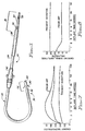
- FIG. 1 is a side view of a pacing lead 20 according to the present invention.
- the lead 20 is provided with an elongate lead body 22 which includes electrical conductors (not shown) covered with an insulation sheath 24.
- the insulation sheath is preferably fabricated of silicone rubber, polyurethane or some other suitable biocompatible, biostable polymer.
- a connector assembly 28 which is provided with sealing rings 30 and which carries at least one electrical connector pin 32, and may also carry an anode terminal ring electrical connector 33.
- the connector assembly 28 is constructed using known techniques and is preferably fabricated of silicone rubber, polyurethane or some other suitable polymer for insulating.
- the connector pin (or pins for bipolar or multipolar leads) 32 and connector 33 are preferably fabricated of stainless steel or some other suitable conductive material.
- a fixation or lead anchoring sleeve 42 slidably mounted around the lead body 22, serves to stabilise the pacing lead 20 at the site of venous insertion by means of suture ties about the sleeve and underlying fascia.
- the electrode assembly 36 of Figure 1 is shown in greater cross-sectional detail in Figure 2.
- the electrode assembly 36 includes a conductive electrode 50 as well as the tine sheath 38 and the tines 40 thereof.
- the conductive electrode 50 is preferably a unitary construction including, at its proximal end, a cylindrical portion 52 defining an axial bore 54.
- a coil-wound conductor 56 of the lead body 22 is inserted into the axial bore 54 and affixed in electrical contact thereto, for example, by mechanical crimping or welding.
- the conductive electrode 50 includes a neck area 58 having a reduced diameter from the cylinder 52 which provides a recessed area into which an interior extending ridge of the tine sheath 38 is inserted to provide positive engagement of the tine sheath 38 with the conductive electrode 50. Finally, the conductive electrode 50 terminates at an electrode distal tip 60.
- the electrode distal tip 60 has a generally mushroom shape, such that the electrode distal tip 60 has a part hemispherical surface which is intended to provide electrical contact with the endocardial tissue. It should be appreciated that the electrode distal tip 60 may define a number of different profiles, from hemispherical to essentially planar with rounded edges. As shown in Figure 2 and more specifically in Figure 3, the electrode distal tip 60 includes at least one and preferably two or more recessed areas or grooves 62. The grooves 62 define generally pie-shaped segments shown in Figure 3. These pie-shaped segments of the electrode distal tip 60 will be generally referred to as the plateaux 64 in this specification, although it is recognised that the plateaux may be part hemispherical in shape, or may have other configurations.
- the grooves 62 provide a means for capturing blood born cells during implant of the pacing lead.
- the grooves 62 in the electrode distal tip 60 as illustrated herein provide a capture site for blood cells and elements therein, including platelets, thrombin, red blood cells, and other elements, and the initiation of the formation of blood clotting upon insertion of the electrode assembly 36 into the vein of the recipient.
- the platelets, thrombin, red blood cells, and other blood borne elements which are captured within the grooves 62 begin to form a thrombosis or blood clot.
- This blood clot upon contact with the endocardial tissue, helps assist in affixing the electrode distal tip 60 to the endocardial tissue, to provide immediate stabilisation of the electrode to endocardial tissue.
- the grooves 62 also help to capture some amount of the soft, mouldable endocardial tissue to assist also in immediately stabilising the electrode tip.
- the grooves 62 while relatively shallow, will capture enough platelets, red blood cells, and other elements and endocardial tissue during the passage from the venous insertion point to the endocardium of the heart, generally to fill a majority of the recessed area. Accordingly, for a lead's electrode distal tip 60 having a diameter of between one and four millimeters, and a preferred diameter of two millimeters, and a preferred diameter of two millimeters, the grooves 62 will have a depth in the range of between 0.1 and 0.5 millimeters and a width of between about 0.2 and 1.0 millimeters; and preferably, about 0.4 and 0.4 millimeters, respectively. Further, it is preferred that the edges of the grooves 62 be radiused in order to minimise tissue damages.
- the electrode distal tip 60 is also treated to increase the porosity and active surface area, thereby enhancing the electrical efficiency by lowering the polarisation and increasing capacitance.
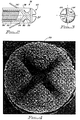
- This texturising treatment of the electrode distal tip 60 includes depositing generally spherical shaped small particles on the surface of the electrode distal tip 60, including all the surfaces defining the grooves 62 as well as the plateaux 64. These generally spherical particles 70 are illustrated in the electron microscope photograph views shown in Figures 4 and 5 in greater detail.
- the conductive electrode 50 is made of a platinum-iridium composition.
- the platinum-iridium alloy has a composition of 90% platinum, 10% iridium by weight.
- the generally spherical particles 70 are preferably platinum/iridium (90%/100%) particles having a generally smooth surfaced spheroidal shape. It should be recognised however, that the electrode and the particles may be made of other suitable materials, such as titanium.
- the diameters of the spherical particles 70 should be in the range of between about 20 and 200 ⁇ m (0.1mm to 0.20mm), and preferably be in the range of between 20 and 80 ⁇ m (0.02mm to 0.08mm). Additionally, it is preferred that the spherical particles have a distribution of sizes spanning this range.
- two coatings of the spheroidal particles are applied to the base electrode. The first coating is preferred to be of particles in the range of 40-80 ⁇ m and the second coating 20-40 ⁇ m.
- the generally spheroidal particles 70 Upon affixation to the electrode distal tip 60, the generally spheroidal particles 70 will create a plurality of pore sites and interstitial porosity for chronic ingrowth of tissue.
- the affixation of the spheroidal particles 70 having the preferred sizes and distribution of size, the interstitial porosity defined by the multiple layers of spheroidal particles 70 will have passageway dimensions which allow the passage of red blood cells (typically having a six ⁇ m (0.006mm) diameter) and other blood borne elements.
- the spheroidal particles 70 preferably have a generally smooth surface in order to minimise the amount of irritation of the endocardial tissue caused by the electrode distal is 60 during the continuous beating of the heart.
- the affixation of the spherical particles 70 also substantially increases the true surface areas of the electrode distal tip 60.
- the true surface area of the electrode distal tip 60 is increased by as much as a factor of five to twenty times.
- the electrode distal tip 60 an the particles 70 are treated with a surface coating means for increasing the active electrical surface area and enhancing the electrical efficiency by reducing the degree of electrochemical polarisation and increasing the electrical capacitance of the electrode distal tip 60 during operation of the pacemaker system.
- a nonmetallic material such as titanium nitride is used as the surface coating, as shown in the electron microscope photograph of Figure 6.
- a portion of the surface of the electrode distal tip 60 is enlarged by a factor of eight thousand.
- the surface coating further increases the true surface area of the electrode distal tip 60 by a significant factor.
- the surface coating substantially enhances the electrical characteristics of the electrode distal tip 60.
- the surface coating increases the electrode's electrical capacitance and lowers the polarisation developed at the electrode distal tip 60.
- the surface coating on the spherical particles 70 while appearing to create relatively sharp edges thereon, does not result in irritation to the endocardial tissue because the relative size of the crystalline structure of the surface coating is substantially smaller than the heart's cells, the other cardiovascular tissue, and the blood elements which the coating will contact (i.e., red blood cells having an approximate diameter of six microns).
- the surface coating is deposited in a manner such that the thickness of the surface coating attached to the spherical particles 70 is in a range of between one to thirty ⁇ m. While titanium nitride is the preferred surface coating material, other suitable nonmetallic coating materials, such as, for example, carbon, iridium oxide, and titanium oxide; and platinum oxide may also be applied as the surface coating of the electrode distal tip 60 following affixation of the spherical particles 70.
- FIG. 7 is a graph depicting the generalised pacing threshold performance of an electrode constructed according to the present invention.
- the pacing threshold energy of microjoules is depicted on the Y-axis as a function of time, in weeks, along the X-axis, for two exemplary lead designs of the prior art and the lead 20 according to the present invention.
- the average energy threshold is based upon voltage thresholds at various pulse durations and assumes pacing impedance remains generally constant.
- the increase in the average energy requirement within the four to six weeks following implant is substantial for the pacing leads of the prior art.
- the lead 20 of the present invention exhibits virtually no threshold increase, and remains relatively level at a lower average energy than either of the prior art leads. As may be appreciated, this will result in an increased threshold safety margin and/or a substantial increase in the useful life of the pacemaker system, given a fixed battery capacity, since the required energy to stimulate the heart is low.
- FIG. 8 graphically depicts the improved cardiac signal sensing capability of the electrode design of the present invention.
- the cardiac signal amplitude in millivolts is depicted on the Y-axis as a function of time (in weeks) on the X-axis, for the lead of the present invention and a lead according to the prior art.
- the lead of the present invention maintains a relatively uniform high level for the cardiac signal amplitude, as compared to the prior lead which has both a lower initial level and a reduction over the course of the first two to three weeks. The primary difference reduced as a result of the significantly reduced polarisation of the lead of the present invention, as discussed in greater detail below.
- Figures 9 and 10 are a cross-sectional view and an end view of an alternative embodiment of the distal tip of an electrode 80 for the electrode assembly 36.
- the electrode distal tip 80 includes a plurality of generally parallel grooves 82 defining therebetween generally parallel strip plateaux sections 84. In the embodiment shown, three grooves 82 are illustrated; however, it should be understood that a limited number of additional grooves may be incorporated.
- the number of the grooves 82 is limited by the size of the grooves appropriate for the capture of platelets, red blood cells, and other blood elements and tissue as described above, and the diameter of the electrode distal tip 80. In the preferred configuration, the diameter of the electrode distal tip 80 will be in the range of one to four millimeters. Preferably, the diameter of the electrode distal tip 80 is approximately two millimeters.
- Figures 11 and 12 are a cross-sectional view and an end view respectively of a second alternative embodiment of an electrode distal tip 90 for the electrode assembly 36.
- This embodiment includes a plurality of intersecting grooves 92 which define therebetween generally square shaped plateaux 94.
- the plateaux may be round in shape as shown by reference numerals 95.
- the grooves 92 are dimensioned so as to allow capture of platelets, red blood cells, and other blood elements during insertion of the lead 20 into the patient.
- the grooves 92 are cut into the electrode distal tip 90 such that a base 96 of the grooves, when viewed in cross-section, defines a part hemispherical inner surface.
- both the surfaces of the plateaux 94 and the base 96 of the grooves 92 define part hemispherical base surface configuration can also be incorporated into the designs illustrated in Figures 2 and 3, as well as in the design of Figures 9 and 10.
- FIG. 13 An additional alternative design configuration which may be incorporated into any of the three embodiments shown in Figures 2 and 3, 9 and 10, or 11 and 12, is shown in Figure 13.
- the base of the grooves 102 is illustrated as either having a flat surface 104 or a concave inner surface 106.
- the base of the groove or grooves may define a concave base surface, a flat base surface may define a concave base surface, a flat base surface or part spherical base surface profile.
- the walls 108 ( Figure 13) defining the grooves of the embodiments have generally flat surfaces which are parallel to the axis of the distal tip, it will be appreciated that the walls of the grooves may be generally angled with respect to the axis of the distal tip.
- the corners at the base and the peaks of the grooves for any of the above described embodiments may be radiused to a radius of curvature of between about 0.001mm and 0.5mm, as opposed to having sharp edges.
- the grooves of any of the above embodiments may be formed by any of the methods selected from the group including stamping, milling, moulding and electrochemical machining.
- the generally spherical particles 70 which are applied to the surfaces of the electrode distal tip 60 as discussed above with respect to Figure 1 are also applied to the alternative embodiments as is the titanium nitride or alternative surface coating treatment.
- the spherical particles 70 are preferably attached to the surfaces of the electrode distal tip by a process such as sintering, laser fusion or welding, injection and moulding casting.
- the surface coating of titanium nitride or alternative material is applied to the spherical particles 70 of the electrode distal tips 60 or any of the alternative embodiments by a process such as sintering in an appropriate environment, vapour deposition, electroplating and sputtering.
- the surface coating is illustrated in Figures 14 and 15 which schematically depict top and side views respectively of the microporous surface structure.
- Figure 14 illustrates the generally pyramid-like shape of the microporous coating.
- Figure 15 a side or profile view of the microporous surface coating illustrates the triangular peaks of the coating, and more importantly the areas between the peaks of the coating which provide high surface porosity.
- the surface porosity or microporosity is in excess of fifty percent (50%), and preferably in the range of between sixty-five percent (65%) and seventy percent (70%).
- a pacing lead having an electrode tip configured in accordance with the foregoing detailed description exhibits superior pacing performance.
- the primary reason for the superior performance is the reduction in polarisation proximate the electrode tip.
- the "polarisation voltage" for a pacing lead is herein defined to be the voltage differential developed between the leading edge and the trailing edge of a reference electrical impulse.
- the reference electrical impulse is a 10 mA (milliampere), one millisecond, square wave, constant current pulse from a pulse generator.
- the electrode is immersed in a 0.15 molar sodium chloride (NaCl) solution, at a pH of 7, and temperature of 37°C.
- the polarisation voltage measured according to the above test will be influenced substantially by the size, shape, material, and surface nature of the electrode distal tip for a given pacing lead.
- the polarisation voltages will be different for a 3mm2 tip and a 5mm2 tip.
- two pacing leads having 5mm2 electrode tips will have characterising polarisation voltages which will depend on their particular profile, construction, material and surface nature.
- the pacing lead electrode which has a lower polarisation voltage for any given electrode design, or more simply the circumferential area, (cross-sectional area for a non-round tip) will be the more desirable pacing lead.
- a "polarisation index” is herein defined.
- the polarisation index is the polarisation voltage Pv divided by the circumferential area CA (or cross-sectional area) of the electrode at its widest diameter.
- the circumferential area CA is equal to ⁇ (d/2)2
- the pacing leads of the present invention as disclosed in detail above have a polarisation index PI which is less than 100mV/mm2. More particularly, in the preferred embodiments, the pacing leads of the present invention have a polarisation index PI which is less than 50mV/mm2.
- a pacing lead having an electrode tip which combines a surface morphology allowing tissue ingrowth and very low polarisation index levels is highly desirable in the field of implantable cardiac pacing leads.
Landscapes
- Health & Medical Sciences (AREA)
- Heart & Thoracic Surgery (AREA)
- Vascular Medicine (AREA)
- Cardiology (AREA)
- Engineering & Computer Science (AREA)
- Biomedical Technology (AREA)
- Nuclear Medicine, Radiotherapy & Molecular Imaging (AREA)
- Radiology & Medical Imaging (AREA)
- Life Sciences & Earth Sciences (AREA)
- Animal Behavior & Ethology (AREA)
- General Health & Medical Sciences (AREA)
- Public Health (AREA)
- Veterinary Medicine (AREA)
- Electrotherapy Devices (AREA)
Abstract
Description
- This invention relates generally to an implantable pacing lead and more specifically to a pacing lead having a high efficiency tissue stimulating and signal sensing porous electrode for use with a cardiac pacemaker and a method for making the porous electrode.
- For a cardiac pacemaker, implant lifetime is determined by the energy delivered per pulse. The pacemaker will have a longer life if the energy delivered per pulse is maintained at a minimum. Alternatively, the energy can also be used to provide for more features in the pacemaker. The design of an implantable pacing lead which is used with the pacemaker is influenced by the optimum signal for pacing stimulation. Physiologically, a cardiac pacemaker must be capable of generating a signal with a sufficient magnitude to depolarize the excitable cells of the endocardium. The electrode size, material, surface nature, and shape; the body tissue or electrolyte conductivity; and the distance separating the electrode and the excitable tissue, combine to determine the energy required of the pacemaker. Accordingly, the main factors to be considered with regard to the design of implantable pacing lead's electrode are: the size, surface nature, material and shape; the fixation of the electrode to the tissue; and the endocardial tissue reaction.
- In selecting a pacemaker, the current drain, and therefore the implant lifetime, is determined by the impedance to pacing pulses. The pacemaker lead's electrode must be capable of delivering a pacing pulse with a pulse width generally in the range of 0.01-2.0 milliseconds and 0.5 to 10.0 volts to the tissue, and to also sense and transmit a QRS signal arising in the atria and ventricles of the heart to the pacemaker circuitry. Generally, the electrode-electrolyte system impedance is higher for sensing than for pacing. Pacing leads for pacing and sensing in the atrium, which can exhibit different stimulation and depolarization parameters than the ventricle, are also required.
- The electrode-endocardial tissue system impedance characteristics may be understood in terms of an interface component and a spreading resistance component. The interface component occurs within a few microns of the surface of the electrode. The spreading resistance component depends predominantly on the tissue resistivity. Generally, the former reflects the charge transfer characteristics of the electrode-tissue interface influenced mostly by the surface area and material of the electrode, and the latter reflects the overall size and shape of the electrode; the surface nature of electrode; and the resistivity of the tissue.
- The current drain of a pacemaker is determined by the impedance of the pacemaker circuitry, the nature of the electrode lead resistance, and the characteristics of the electrode tip interface with the electrolyte system. For a given pacemaker circuit and electrode lead design, the current drain is well defined. Thus, the nature of the electrode-endocardial tissue interface determines the overall current requirements of the system.
- As an additional design factor, the most significant frequency of the pacing pulse is of the order of 1 KHz. At this frequency, the interface impedance is small and most of the impedance to the pacing pulses is due to the bulk or spreading impedance. This is determined by the shape and size of the electrode tip and is generally inversely related to the radius of the electrode tip.
- The most significant frequency components of a signal to be sensed, i.e., the ventricular QRS, are in the bandwidth of 20-100 Hz. In this region, the interface impedance of the sensed signal becomes the most significant. The interface impedance is determined in large part by the microsurface area of the electrode tip and develops within a few microns of the surface. As described herein, the microsurface area of a porous electrode tip is the wettable surface, area which includes all of the exposed and interstitial porosity surfaces of the electrode tip.
- As a final design consideration, it has been determined that the pacing or stimulation threshold is a reflection of the electrical energy required for a pulse to initiate a cardiac depolarization. The stimulation threshold typically rises for a period of a few weeks after the implant of a cardiac pacemaker generally as a result of an increase in the spacing between the electrode and the excitable tissue. The increase occurs due to the development of a fibrous capsule around the electrode tip. The thickness of the fibrous capsule is generally dependent upon the mechanical characteristics of the distal end of the lead (i.e., stiff or flexible); the geometry of the electrode tip; and the microstructure of the electrode tip, such as a porous electrode surface and the electrode material itself. In this regard, the environment of the endocardium must be considered. Specifically, the constant beating of the heart can cause the electrode to pound and rub against the endocardium, causing irritation and a significant subsequent inflammatory response, which ultimately results in healing, and the development of a fibrotic tissue capsule about the electrode tip. Also, a rough surface microstructure or one with sharp protrusions for the electrode will tend to be abrasive or traumatic on the abutting heart cells, also causing irritation, which also tends to cause the development of a thicker fibrotic capsule.
- In view of the above characteristics of an electrode and its implantology issues for a cardiac pacemaker, it is clear that an electrode tip with a small geometric surface area (resulting in higher pacing impedance) will have a low current drain. However, in order to enhance sensing, the same electrode tip should have a large microsurface area and be of such a material to result in a low polarization and high capacitance which, in turn, results in a low sensing impedance and improved sensing. A cardiac pacemaker electrode tip that is constructed to be porous is therefore preferred in order to best satisfy these requirements.
- In a pacemaker electrode, minimal tissue reaction is desired around the tip, but firm intimate attachment of the electrode to the tissue is essential to minimize any electrode movement relative to the abutting tissue. A porous electrode tip with macro tissue entrapping structure allows rapid fibrous tissue growth into a hollow area or cavities in the electrode tip to facilitate and enhance attachment of the electrode to the heart. A reduced lead dislodgement rate is also expected as a result of such tissue ingrowth. A further aspect of importance is selection of porosity size, which must be such as to accommodate economical construction techniques, overall dimensional tolerances, and tissue response constraints.
- According to the invention, there is provided an implantable lead for use with a cardiac pacemaker comprising an electrical conductor having an outer insulating sheath, an electrical connector coupled to the proximal end of the conductor and an electrode coupled to the distal end of the conductor, characterised in that the electrode has an electrode tip macrostructure geometry defining at least two plateau sections separated and the recessed groove section including surfaces having affixed thereto at least one layer of generally spheroidal conductive particles coated with a layer of nonmetallic material.
- Preferably, the conductive particles have diameters ranging from 10 to 200 µm, and are configured in at least one layer on the electrode surfaces to provide interstitial porosity for tissue ingrowth. Suitable materials include platinum, titanium, palladium, platinum iridium and carbon.
- It may be that the electrode tip includes two recessed areas configured to intersect one another thereby defining a cross shape; or includes at least two parallel aligned recessed areas defining at least three generally aligned plateau areas, the corners of these plateau areas such defining an angle of at least sixty degrees, or includes at least two sets of multiple, parallel aligned, recessed areas, configured to have the multiple aligned recessed areas of the sets intersecting one another.
- Preferably, the groove profile defined by a depth of between 0.1 and 1.0 millimetres, a width of between about 0.2 and 1.5 millimetres, and each edge of the groove is optionally radiused with a radius of curvature of between about 0.001 and 0.5 millimetres.
- Suitable non-metallic materials include titanium nitride, iridium oxide, titanium oxide, platinum oxide, palladium oxide or an activated form of carbon. Preferably, the layer of non-metallic material has a surface morphology which results in a porosity of greater than about fifty percent.
- The invention also extends to a method of forming an implantable lead for use with a cardiac pacemaker which comprises covering an electrical conductor in an insulative sheath, coupling an electrical connector to the proximal end of the conductor and coupling an electrode to the distal end of conductor, characterised by: forming the electrode tip macrostructure geometry to define at least two plateau sections separated by at least one recessed groove section; affixing to the plateau sections and the recessed groove section a plurality of generally spherical conductive particles; and coating the particles with a layer of non-metallic material preferably selected from titanium nitride, palladium, platinum oxide, iridium oxide, and activated carbon.
- Preferably, the conductive particles are coated by vapour deposition, sintering, electroplating and electrode sputtering, preferably to a thickness of 20 to 30 µm. They may be affixed to the electrode distal tip by powder sintering, laser fusion, welding, injection moulding, or casting, and are preferably affixed in a series of successive steps in which a portion of the particles are affixed in each successive step.
- The pacing tip electrode of the preferred embodiment of the present invention is a five square millimeter platinum-iridium (90%/10%) porous electrode with recessed areas or slots in the shape of a cross formed into the surface. The grooves allow for acute electrode stabilization tissue ingrowth as a result of naturally occurring clot formation during insertion and helps result in immediate immobilization of the electrode upon implant. A porous coating of 20-80 µm (micron) diameter spherical platinum-iridium (90%/10%) particles are deposited on the surface of the base electrode to obtain a porous macrostructure for chronic tissue ingrowth and also for extending the active surface area. Preferably, the particles are deposited in a two-step process where the first layer of particles is made up of 40 to 80 µm spheroidal particles. The second layer is made up of 20 to 40 µm spheroidal particles. The result is a clumping of the particles producing a uniformly textured surface with randomized particle attachment. Chronic tissue ingrowth into this clumped, porous macrostructure enhances the electrode stabilization.
- The additional mirostructure surface coating is applied on these particles to increase the active surface area and enhance electrical efficiency by lowering polarization and increasing electrical capacitance. The macrostructure is preferably created by sintering the platinum-iridium particles to the platinum-iridium electrode tip. The microstructure coating is preferably created by reactive sputtering of titanium nitride onto the platinum-iridium particles.
- In its broadest sense, the invention is considered to extend to an implantable pacing lead for use with a cardiac pacemaker comprising: an electrical conductor having a proximal end and a distal end; an insulative sheath covering said conductor; an electrical connector affixed to said proximal end of said conductor; and an electrode assembly affixed to said distal end of said conductor, said electrode assembly including a porous electrode distal tip having a polarisation index PI which is less than 100 mV/mm2.
- Preferably, the distal tip further comprises means for capturing blood cells during insertion of said electrode assembly into a human recipient, and for promoting clot formation and endocardial tissue capture thereof to aid fixation of said electrode distal tip to endocardial tissue; means for providing interstitial porosity and for increasing surface area of said electrode distal tip; and coating means for enhancing the electrical characteristics of said electrode distal tip, for increasing the electrical capacitance, and for reducing electrochemical polarisation at the electrode-endocardial tissue interface during pacing use.
- Preferably, means for capturing blood cells and endocardial tissue and promoting clot formation and tissue ingrowth comprises: at least one recessed area traversing said electrode distal tip, said recessed area having a generally U-shaped profile defined by generally vertical walls and a base, said base of said recessed area having a transverse profile shape selected from the group consisting of semi-hemispherical, flat and concave. Preferably, the means for providing interstitial porosity and increasing surface area comprises: a plurality of generally smooth surfaced spheroidal particles affixed to the surface of said electrode distal tip including said walls and base of said at least one recessed area.
- Preferably, the coating means comprises: a surface coating applied to the surfaces of said distal tip electrode and said spheroidal particles, thereon, said surface coating comprising a microscopically thin layer of a non-metallic material selected from the group consisting of titanium nitride, titanium oxide, carbon, iridium oxide, and platinum oxide, said surface coating applied by a process selected from the group consisting of sintering, vapour deposition, electroplating and sputtering.
- The invention may be carried into practice in various ways and some embodiments will now be described by way of example with reference to the accompanying drawings, in which:-
- Figure 1 is a side view of a pacing lead according to the present invention;
- Figure 2 is a cross-sectional view of the distal tip of the electrode of the lead shown in Figure 1;
- Figure 3 is an end view of the distal tip of the electrode of the lead shown in Figure 1 and;
- Figure 4 is an electron microscope photograph of the distal tip of Figure 3, magnified by a factor of 50;
- Figure 5 is an electron microscope photograph of part of the distal tip of Figure 3, magnified a factor of 500;
- Figure 6 is an electron microscope photograph of part of the distal tip of Figure 3, magnified by a factor of 8000.
- Figure 7 is a graph of the pacing threshold performance of an electrode constructed according to the present invention;
- Figure 8 is a graph showing cardiac signal sensing for an electrode according to the present invention;
- Figure 9 is a cross-sectional view of an alternative configuration for the distal tip of Figure 1;
- Figure 10 is an end view of an alternative tip configuration of Figure 9.
- Figure 11 is a cross-sectional view of a second alternative configuration for the distal tip of Figure 1;
- Figure 12 is an end view of the alternative tip configuration of Figure 11;
- Figure 13 is a cross-sectional view of a further alternative configuration for the distal tip; and
- Figures 14 and 15 schematically depict top and side views respectively of the microporous surface structure.
- Figure 1 is a side view of a
pacing lead 20 according to the present invention. Thelead 20 is provided with an elongatelead body 22 which includes electrical conductors (not shown) covered with aninsulation sheath 24. The insulation sheath is preferably fabricated of silicone rubber, polyurethane or some other suitable biocompatible, biostable polymer. At theproximal end 26 of thepacing lead 20, there is aconnector assembly 28, which is provided with sealing rings 30 and which carries at least oneelectrical connector pin 32, and may also carry an anode terminal ringelectrical connector 33. Theconnector assembly 28 is constructed using known techniques and is preferably fabricated of silicone rubber, polyurethane or some other suitable polymer for insulating. The connector pin (or pins for bipolar or multipolar leads) 32 andconnector 33 are preferably fabricated of stainless steel or some other suitable conductive material. - At the
distal end 34 of thepacing lead 20, there is anelectrode assembly 36 which is discussed in more detail below. Immediately behind the distal end of theelectrode assembly 36, there is atine sheath 38 which includes a plurality of individualflexible tines 40. Thetines 40 engage endocardial tissue and urge theelectrode assembly 36 into contact with the endocardium, in a direction parallel to the axis of theelectrode assembly 36. Thetines 40 are more fully described in U.S. Patent No. 3,902,501. A fixation or lead anchoringsleeve 42, slidably mounted around thelead body 22, serves to stabilise thepacing lead 20 at the site of venous insertion by means of suture ties about the sleeve and underlying fascia. - The
electrode assembly 36 of Figure 1 is shown in greater cross-sectional detail in Figure 2. As illustrated, theelectrode assembly 36 includes aconductive electrode 50 as well as thetine sheath 38 and thetines 40 thereof. Theconductive electrode 50 is preferably a unitary construction including, at its proximal end, acylindrical portion 52 defining anaxial bore 54. A coil-wound conductor 56 of thelead body 22 is inserted into theaxial bore 54 and affixed in electrical contact thereto, for example, by mechanical crimping or welding. Proceeding toward the distal end of theconductive electrode 50, theconductive electrode 50 includes aneck area 58 having a reduced diameter from thecylinder 52 which provides a recessed area into which an interior extending ridge of thetine sheath 38 is inserted to provide positive engagement of thetine sheath 38 with theconductive electrode 50. Finally, theconductive electrode 50 terminates at an electrodedistal tip 60. - As shown in Figure 2, the electrode
distal tip 60 has a generally mushroom shape, such that the electrodedistal tip 60 has a part hemispherical surface which is intended to provide electrical contact with the endocardial tissue. It should be appreciated that the electrodedistal tip 60 may define a number of different profiles, from hemispherical to essentially planar with rounded edges. As shown in Figure 2 and more specifically in Figure 3, the electrodedistal tip 60 includes at least one and preferably two or more recessed areas orgrooves 62. Thegrooves 62 define generally pie-shaped segments shown in Figure 3. These pie-shaped segments of the electrodedistal tip 60 will be generally referred to as theplateaux 64 in this specification, although it is recognised that the plateaux may be part hemispherical in shape, or may have other configurations. - As discussed above the particular structure, i.e., the size, shape and porosity, of the electrode
distal tip 60 is of particular importance to the functioning of thepacing lead 20, and the cardiac pacemaker system. Thegrooves 62 provide a means for capturing blood born cells during implant of the pacing lead. Specifically, thegrooves 62 in the electrodedistal tip 60 as illustrated herein, provide a capture site for blood cells and elements therein, including platelets, thrombin, red blood cells, and other elements, and the initiation of the formation of blood clotting upon insertion of theelectrode assembly 36 into the vein of the recipient. As thelead body 22 of thepacing lead 20 is fed into the vein of the recipient, and theelectrode assembly 36 proceeds to the heart, the platelets, thrombin, red blood cells, and other blood borne elements which are captured within thegrooves 62 begin to form a thrombosis or blood clot. This blood clot, upon contact with the endocardial tissue, helps assist in affixing the electrodedistal tip 60 to the endocardial tissue, to provide immediate stabilisation of the electrode to endocardial tissue. Thegrooves 62 also help to capture some amount of the soft, mouldable endocardial tissue to assist also in immediately stabilising the electrode tip. - It is anticipated that the
grooves 62, while relatively shallow, will capture enough platelets, red blood cells, and other elements and endocardial tissue during the passage from the venous insertion point to the endocardium of the heart, generally to fill a majority of the recessed area. Accordingly, for a lead's electrodedistal tip 60 having a diameter of between one and four millimeters, and a preferred diameter of two millimeters, and a preferred diameter of two millimeters, thegrooves 62 will have a depth in the range of between 0.1 and 0.5 millimeters and a width of between about 0.2 and 1.0 millimeters; and preferably, about 0.4 and 0.4 millimeters, respectively. Further, it is preferred that the edges of thegrooves 62 be radiused in order to minimise tissue damages. - The electrode
distal tip 60 is also treated to increase the porosity and active surface area, thereby enhancing the electrical efficiency by lowering the polarisation and increasing capacitance. This texturising treatment of the electrodedistal tip 60 includes depositing generally spherical shaped small particles on the surface of the electrodedistal tip 60, including all the surfaces defining thegrooves 62 as well as theplateaux 64. These generallyspherical particles 70 are illustrated in the electron microscope photograph views shown in Figures 4 and 5 in greater detail. - Preferably, the
conductive electrode 50 is made of a platinum-iridium composition. In the preferred embodiment, the platinum-iridium alloy has a composition of 90% platinum, 10% iridium by weight. The generallyspherical particles 70 are preferably platinum/iridium (90%/100%) particles having a generally smooth surfaced spheroidal shape. It should be recognised however, that the electrode and the particles may be made of other suitable materials, such as titanium. The diameters of thespherical particles 70 should be in the range of between about 20 and 200 µm (0.1mm to 0.20mm), and preferably be in the range of between 20 and 80 µm (0.02mm to 0.08mm). Additionally, it is preferred that the spherical particles have a distribution of sizes spanning this range. Preferentially, two coatings of the spheroidal particles are applied to the base electrode. The first coating is preferred to be of particles in the range of 40-80 µm and the second coating 20-40 µm. - Upon affixation to the electrode
distal tip 60, the generallyspheroidal particles 70 will create a plurality of pore sites and interstitial porosity for chronic ingrowth of tissue. Preferably, the affixation of thespheroidal particles 70 having the preferred sizes and distribution of size, the interstitial porosity defined by the multiple layers ofspheroidal particles 70 will have passageway dimensions which allow the passage of red blood cells (typically having a six µm (0.006mm) diameter) and other blood borne elements. By allowing the migration of red blood cells and other blood carried substances through the interstitial porosity, the events resulting in chronic tissue ingrowth are initiated. - The
spheroidal particles 70 preferably have a generally smooth surface in order to minimise the amount of irritation of the endocardial tissue caused by the electrode distal is 60 during the continuous beating of the heart. In addition to providing interstitial porosity for tissue ingrowth, the affixation of thespherical particles 70 also substantially increases the true surface areas of the electrodedistal tip 60. Generally, by use of thesespheroidal particles 70, the true surface area of the electrodedistal tip 60 is increased by as much as a factor of five to twenty times. - Following affixation of the
spherical particles 70 to the electrodedistal tip 60, the electrodedistal tip 60 an theparticles 70 are treated with a surface coating means for increasing the active electrical surface area and enhancing the electrical efficiency by reducing the degree of electrochemical polarisation and increasing the electrical capacitance of the electrodedistal tip 60 during operation of the pacemaker system. Preferably, a nonmetallic material such as titanium nitride is used as the surface coating, as shown in the electron microscope photograph of Figure 6. In the electron microscope photograph of Figure 6, a portion of the surface of the electrodedistal tip 60 is enlarged by a factor of eight thousand. As may be appreciated from observing this photograph, the surface coating further increases the true surface area of the electrodedistal tip 60 by a significant factor. - In addition to increasing the true surface area, the surface coating substantially enhances the electrical characteristics of the electrode
distal tip 60. The surface coating increases the electrode's electrical capacitance and lowers the polarisation developed at the electrodedistal tip 60. It should also be noted that the surface coating on thespherical particles 70, while appearing to create relatively sharp edges thereon, does not result in irritation to the endocardial tissue because the relative size of the crystalline structure of the surface coating is substantially smaller than the heart's cells, the other cardiovascular tissue, and the blood elements which the coating will contact (i.e., red blood cells having an approximate diameter of six microns). - The surface coating is deposited in a manner such that the thickness of the surface coating attached to the
spherical particles 70 is in a range of between one to thirty µm. While titanium nitride is the preferred surface coating material, other suitable nonmetallic coating materials, such as, for example, carbon, iridium oxide, and titanium oxide; and platinum oxide may also be applied as the surface coating of the electrodedistal tip 60 following affixation of thespherical particles 70. - Figure 7 is a graph depicting the generalised pacing threshold performance of an electrode constructed according to the present invention. In Figure 7, the pacing threshold energy of microjoules is depicted on the Y-axis as a function of time, in weeks, along the X-axis, for two exemplary lead designs of the prior art and the
lead 20 according to the present invention. In the graph, the average energy threshold is based upon voltage thresholds at various pulse durations and assumes pacing impedance remains generally constant. As depicted, the increase in the average energy requirement within the four to six weeks following implant is substantial for the pacing leads of the prior art. By comparison, thelead 20 of the present invention exhibits virtually no threshold increase, and remains relatively level at a lower average energy than either of the prior art leads. As may be appreciated, this will result in an increased threshold safety margin and/or a substantial increase in the useful life of the pacemaker system, given a fixed battery capacity, since the required energy to stimulate the heart is low. - Figure 8 graphically depicts the improved cardiac signal sensing capability of the electrode design of the present invention. In Figure 8 the cardiac signal amplitude in millivolts is depicted on the Y-axis as a function of time (in weeks) on the X-axis, for the lead of the present invention and a lead according to the prior art. As depicted, the lead of the present invention maintains a relatively uniform high level for the cardiac signal amplitude, as compared to the prior lead which has both a lower initial level and a reduction over the course of the first two to three weeks. The primary difference reduced as a result of the significantly reduced polarisation of the lead of the present invention, as discussed in greater detail below.
- Figures 9 and 10 are a cross-sectional view and an end view of an alternative embodiment of the distal tip of an
electrode 80 for theelectrode assembly 36. The electrodedistal tip 80 includes a plurality of generallyparallel grooves 82 defining therebetween generally parallelstrip plateaux sections 84. In the embodiment shown, threegrooves 82 are illustrated; however, it should be understood that a limited number of additional grooves may be incorporated. The number of thegrooves 82 is limited by the size of the grooves appropriate for the capture of platelets, red blood cells, and other blood elements and tissue as described above, and the diameter of the electrodedistal tip 80. In the preferred configuration, the diameter of the electrodedistal tip 80 will be in the range of one to four millimeters. Preferably, the diameter of the electrodedistal tip 80 is approximately two millimeters. - Figures 11 and 12 are a cross-sectional view and an end view respectively of a second alternative embodiment of an electrode
distal tip 90 for theelectrode assembly 36. This embodiment includes a plurality of intersectinggrooves 92 which define therebetween generally square shapedplateaux 94. Alternatively the plateaux may be round in shape as shown by reference numerals 95. As above, thegrooves 92 are dimensioned so as to allow capture of platelets, red blood cells, and other blood elements during insertion of thelead 20 into the patient. In addition, as shown in Figure 11, thegrooves 92 are cut into the electrodedistal tip 90 such that abase 96 of the grooves, when viewed in cross-section, defines a part hemispherical inner surface. Thus, in Figures 11 and 12, both the surfaces of theplateaux 94 and thebase 96 of thegrooves 92 define part hemispherical base surface configuration can also be incorporated into the designs illustrated in Figures 2 and 3, as well as in the design of Figures 9 and 10. - An additional alternative design configuration which may be incorporated into any of the three embodiments shown in Figures 2 and 3, 9 and 10, or 11 and 12, is shown in Figure 13. Here, the base of the
grooves 102 is illustrated as either having aflat surface 104 or a concaveinner surface 106. Thus, in any of the electrode distal tip configurations of the present invention, it is contemplated that the base of the groove or grooves may define a concave base surface, a flat base surface may define a concave base surface, a flat base surface or part spherical base surface profile. - Additionally, while it has been illustrated in the figures that the walls 108 (Figure 13) defining the grooves of the embodiments have generally flat surfaces which are parallel to the axis of the distal tip, it will be appreciated that the walls of the grooves may be generally angled with respect to the axis of the distal tip. In addition, the corners at the base and the peaks of the grooves for any of the above described embodiments may be radiused to a radius of curvature of between about 0.001mm and 0.5mm, as opposed to having sharp edges. The grooves of any of the above embodiments may be formed by any of the methods selected from the group including stamping, milling, moulding and electrochemical machining. The generally
spherical particles 70 which are applied to the surfaces of the electrodedistal tip 60 as discussed above with respect to Figure 1 are also applied to the alternative embodiments as is the titanium nitride or alternative surface coating treatment. Thespherical particles 70 are preferably attached to the surfaces of the electrode distal tip by a process such as sintering, laser fusion or welding, injection and moulding casting. - Finally, the surface coating of titanium nitride or alternative material, is applied to the
spherical particles 70 of the electrodedistal tips 60 or any of the alternative embodiments by a process such as sintering in an appropriate environment, vapour deposition, electroplating and sputtering. - The surface coating is illustrated in Figures 14 and 15 which schematically depict top and side views respectively of the microporous surface structure. Figure 14 illustrates the generally pyramid-like shape of the microporous coating. In Figure 15, a side or profile view of the microporous surface coating illustrates the triangular peaks of the coating, and more importantly the areas between the peaks of the coating which provide high surface porosity. With the foregoing construction, incorporating the microporous surface coating, the surface porosity or microporosity is in excess of fifty percent (50%), and preferably in the range of between sixty-five percent (65%) and seventy percent (70%).
- A pacing lead having an electrode tip configured in accordance with the foregoing detailed description exhibits superior pacing performance. The primary reason for the superior performance is the reduction in polarisation proximate the electrode tip. The "polarisation voltage" for a pacing lead is herein defined to be the voltage differential developed between the leading edge and the trailing edge of a reference electrical impulse. The reference electrical impulse is a 10 mA (milliampere), one millisecond, square wave, constant current pulse from a pulse generator. The polarisation voltage (Pv) for a particular pacing lead is determined by subtracting the leading edge voltage (V1), from the trailing edge voltage (V2) of the reference electrical impulse (Pv = V2 - V1). During measurement of the polarisation voltage, the electrode is immersed in a 0.15 molar sodium chloride (NaCl) solution, at a pH of 7, and temperature of 37°C.
- As may be appreciated by those skilled in the art, the polarisation voltage measured according to the above test will be influenced substantially by the size, shape, material, and surface nature of the electrode distal tip for a given pacing lead. Thus, for an electrode distal tip having a particular profile, and made of a particular material having a particular surface nature, the polarisation voltages will be different for a 3mm² tip and a 5mm² tip. Conversely, two pacing leads having 5mm² electrode tips will have characterising polarisation voltages which will depend on their particular profile, construction, material and surface nature. Generally the pacing lead electrode which has a lower polarisation voltage for any given electrode design, or more simply the circumferential area, (cross-sectional area for a non-round tip) will be the more desirable pacing lead.
- Accordingly, to further characterise pacing lead electrodes and more particularly the pacing lead of the present invention, a "polarisation index" (PI) is herein defined. The polarisation index is the polarisation voltage Pv divided by the circumferential area CA (or cross-sectional area) of the electrode at its widest diameter. Thus, for a semi-spherical electrode having a diameter "d," the circumferential area CA is equal to π (d/2)², and the polarisation index is given by the following formula:

- The pacing leads of the present invention as disclosed in detail above have a polarisation index PI which is less than 100mV/mm². More particularly, in the preferred embodiments, the pacing leads of the present invention have a polarisation index PI which is less than 50mV/mm². A pacing lead having an electrode tip which combines a surface morphology allowing tissue ingrowth and very low polarisation index levels is highly desirable in the field of implantable cardiac pacing leads.
- It should be evident from the foregoing description that the present invention provides many advantages over pacing leads of the prior art.
Claims (14)
- An implantable lead (20) for use with a cardiac pacemaker comprising an electrical conductor having an outer insulating sheath (24), an electrical connector (28) coupled to the proximal end of the conductor and an electrode (36) coupled to the distal end of the conductor, characterised in that the electrode (26) has an electrode tip (60) macrostructure geometry defining at least two plateau sections (64) separated and the recessed groove section (62) including surfaces having affixed thereto at least one layer of generally spheroidal conductive particles (70) coated with a layer of nonmetallic material.
- A lead as claimed in Claim 1, characterised in that the conductive particles (70) have diameters ranging from 10 to 200 µm, and are configured in at least one layer on the electrode surfaces to provide interstitial porosity for tissue ingrowth.
- A lead as claimed in Claim 1 or Claim 2, characterised in that the conductive particles (70) are formed of platinum, titanium, palladium, platinum-iridium or carbon.
- A lead as claimed in any preceding Claim, characterised in that the conductive particles (70) are affixed by a powder sintering process which preferably comprises a series of two to five steps, a proportion of the particles being affixed in successive steps.
- A lead as claimed in any preceding Claim, characterised in that the interstitial porosity areas between the conductive particles (70) have a plurality of passage diameters greater than six µm to allow the passage of blood cells.
- A lead as claimed in any preceding Claim, characterised in that the electrode tip includes two recessed areas (62) configured to intersect one another thereby defining a cross shape; or includes at least two parallel aligned recessed areas (82) defining at least three generally aligned plateau areas (84), the corners of these plateau areas such defining an angle of at least sixty degrees, or includes at least two sets of multiple, parallel aligned, recessed areas (92), configured to have the multiple aligned recessed areas of the sets intersecting one another.
- A lead as claimed in any preceding Claim, characterised in that the recessed groove section (62,82,92) has a profile defined by a depth of between 0.1 and 1.0 millimetres, a width of between about 0.2 and 1.5 millimetres, and each edge of the groove is optionally radiused with a radius of curvature of between about 0.001 and 0.5 millimetres.
- A lead as claimed in any preceding Claim, characterised in that the non-metallic material is titanium nitride, iridium oxide, titanium oxide, platinum oxide, palladium oxide or an activated form of carbon.
- A lead as claimed in any preceding Claim, characterised in that the layer of non-metallic material has a surface morphology which results in a porosity of greater than about fifty percent.
- A lead as claimed in any preceding Claim, characterised in that the electrode (36) has a distal tip and a polarisation index PI which is less than 100mV/mm² and preferably less than 50mV/mm².
- A method of forming an implantable lead (20) for use with a cardiac pacemaker which comprises covering an electrical conductor in an insulative sheath (24), coupling an electrical connector (28) to the proximal end of the conductor and coupling an electrode (36) to the distal end of conductor, characterised by: forming the electrode tip (60) macrostructure geometry to define at least two plateau sections (64) separated by at least one recessed groove section (62); affixing to the plateau sections (64) and the recessed groove section (62) a plurality of generally spherical conductive particles (70); and coating the particles (70) with a layer of non-metallic material preferably selected from titanium nitride, palladium, platinum oxide, iridium oxide, and activated carbon.
- A method as claimed in Claim 11, characterised in that the conductive particles (70) are coated by vapour deposition, sintering, electroplating and electrode sputtering, preferably to a thickness of 20 to 30 µm.
- A method as claimed in Claim 11 or Claim 12, characterised in that the conductive particles (70) are affixed to the electrode distal tip (60) by powder sintering, laser fusion, welding, injection moulding, or casting.
- A method as claimed in any of Claims 11 to 13, characterised in that the conductive particles (70) are affixed in a series of successive steps in which a portion of the particles are affixed in each successive step.
Applications Claiming Priority (2)
| Application Number | Priority Date | Filing Date | Title |
|---|---|---|---|
| US07/892,463 US5318572A (en) | 1992-06-02 | 1992-06-02 | High efficiency tissue stimulating and signal sensing electrode |
| US892463 | 1997-07-14 |
Publications (3)
| Publication Number | Publication Date |
|---|---|
| EP0573275A2 true EP0573275A2 (en) | 1993-12-08 |
| EP0573275A3 EP0573275A3 (en) | 1994-05-25 |
| EP0573275B1 EP0573275B1 (en) | 1997-10-08 |
Family
ID=25399987
Family Applications (1)
| Application Number | Title | Priority Date | Filing Date |
|---|---|---|---|
| EP93304272A Expired - Lifetime EP0573275B1 (en) | 1992-06-02 | 1993-06-02 | High efficiency tissue stimulating and signal sensing electrode |
Country Status (5)
| Country | Link |
|---|---|
| US (1) | US5318572A (en) |
| EP (1) | EP0573275B1 (en) |
| JP (1) | JPH06261953A (en) |
| AU (1) | AU3992193A (en) |
| DE (1) | DE69314383T2 (en) |
Cited By (23)
| Publication number | Priority date | Publication date | Assignee | Title |
|---|---|---|---|---|
| EP0711576A2 (en) * | 1994-11-11 | 1996-05-15 | Pacesetter AB | Electrodes for medical use |
| WO1998031419A1 (en) * | 1997-01-16 | 1998-07-23 | Cardiac Pacemakers, Inc. | Electrode for high impedance heart stimulation |
| EP0916363A2 (en) * | 1997-11-10 | 1999-05-19 | Vitatron Medical B.V. | Pacing lead with porous electrode |
| EP0839552A3 (en) * | 1996-11-02 | 1999-08-11 | W.C. Heraeus GmbH & Co. KG | Electrode for implantation in biological tissue, method for producing same and its use |
| EP0839553A3 (en) * | 1996-11-02 | 1999-08-11 | W.C. Heraeus GmbH & Co. KG | Electrode for implantation in biological tissue, method for producing same and its use |
| EP1264608A1 (en) * | 2001-05-28 | 2002-12-11 | Terumo Kabushiki Kaisha | Composite material for medical applications, tube for medical applications and medical instrument |
| WO2004073790A1 (en) * | 2003-02-18 | 2004-09-02 | Medtronic, Inc. | Biomedical electrode of enhanced surface area |
| EP1421972A3 (en) * | 2002-11-20 | 2004-10-13 | W. C. Heraeus GmbH & Co. KG | Stimulation electrode and use thereof |
| US6889092B2 (en) | 1999-09-24 | 2005-05-03 | Cardiac Pacemakers, Inc. | High impedance electrode assembly |
| WO2010059305A1 (en) * | 2008-11-20 | 2010-05-27 | Cardiac Pacemakers, Inc. | Cell-repelling electrode having a structured surface |
| EP2194914A1 (en) * | 2007-10-08 | 2010-06-16 | Pulse Technologies, Inc. | Optimum surface texture geometry |
| WO2010104642A1 (en) * | 2009-03-11 | 2010-09-16 | Cardiac Pacemakers, Inc. | Implantable medical device lead electrode with consistent pore size structure |
| US8285376B2 (en) | 2004-12-20 | 2012-10-09 | Cardiac Pacemakers, Inc. | Ventricular pacing |
| US8290586B2 (en) | 2004-12-20 | 2012-10-16 | Cardiac Pacemakers, Inc. | Methods, devices and systems for single-chamber pacing using a dual-chamber pacing device |
| US8298608B2 (en) | 2002-12-13 | 2012-10-30 | Heraeus Precious Metals Gmbh & Co. Kg | Method for producing a stimulation electrode |
| US8326423B2 (en) | 2004-12-20 | 2012-12-04 | Cardiac Pacemakers, Inc. | Devices and methods for steering electrical stimulation in cardiac rhythm management |
| US8423139B2 (en) | 2004-12-20 | 2013-04-16 | Cardiac Pacemakers, Inc. | Methods, devices and systems for cardiac rhythm management using an electrode arrangement |
| US8538521B2 (en) | 2004-12-20 | 2013-09-17 | Cardiac Pacemakers, Inc. | Systems, devices and methods for monitoring efficiency of pacing |
| US8543203B2 (en) | 2004-12-20 | 2013-09-24 | Cardiac Pacemakers, Inc. | Endocardial pacing devices and methods useful for resynchronization and defibrillation |
| US8565880B2 (en) | 2010-04-27 | 2013-10-22 | Cardiac Pacemakers, Inc. | His-bundle capture verification and monitoring |
| US8688234B2 (en) | 2008-12-19 | 2014-04-01 | Cardiac Pacemakers, Inc. | Devices, methods, and systems including cardiac pacing |
| US8880169B2 (en) | 2004-12-20 | 2014-11-04 | Cardiac Pacemakers, Inc. | Endocardial pacing relating to conduction abnormalities |
| WO2021188559A1 (en) * | 2020-03-18 | 2021-09-23 | Bvw Holding Ag | Microstructured hemostat |
Families Citing this family (59)
| Publication number | Priority date | Publication date | Assignee | Title |
|---|---|---|---|---|
| US5534022A (en) * | 1994-11-22 | 1996-07-09 | Ventritex, Inc. | Lead having an integrated defibrillation/sensing electrode |
| US5683443A (en) * | 1995-02-07 | 1997-11-04 | Intermedics, Inc. | Implantable stimulation electrodes with non-native metal oxide coating mixtures |
| US5654030A (en) * | 1995-02-07 | 1997-08-05 | Intermedics, Inc. | Method of making implantable stimulation electrodes |
| DE19507929A1 (en) * | 1995-02-24 | 1996-09-05 | Biotronik Mess & Therapieg | Electrode system for measuring the monophasic action potential |
| DE29603805U1 (en) | 1996-03-01 | 1997-07-03 | Michel, Ulrich, Dipl.-Ing., 67657 Kaiserslautern | Device for transvenous cardioversion of atrial fibrillation or atrial flutter |
| US6078840A (en) * | 1997-04-30 | 2000-06-20 | Medtronic, Inc. | Medical electrical lead having improved fixation |
| US6111052A (en) | 1997-04-30 | 2000-08-29 | Medtronic, Inc. | Polyurethane and polyurea biomaterials for use in medical devices |
| US6212434B1 (en) | 1998-07-22 | 2001-04-03 | Cardiac Pacemakers, Inc. | Single pass lead system |
| US6152954A (en) | 1998-07-22 | 2000-11-28 | Cardiac Pacemakers, Inc. | Single pass lead having retractable, actively attached electrode for pacing and sensing |
| US6085119A (en) | 1998-07-22 | 2000-07-04 | Cardiac Pacemakers, Inc. | Single pass endocardial lead for multi-site atrial pacing |
| US6501994B1 (en) | 1997-12-24 | 2002-12-31 | Cardiac Pacemakers, Inc. | High impedance electrode tip |
| US6321122B1 (en) | 1998-07-22 | 2001-11-20 | Cardiac Pacemakers, Inc. | Single pass defibrillation/pacing lead with passively attached electrode for pacing and sensing |
| JPH11333000A (en) * | 1998-05-27 | 1999-12-07 | Cardio Pacing Research Laboratory:Kk | Electrode lead for vital plantation |
| US6463334B1 (en) | 1998-11-02 | 2002-10-08 | Cardiac Pacemakers, Inc. | Extendable and retractable lead |
| US6501990B1 (en) | 1999-12-23 | 2002-12-31 | Cardiac Pacemakers, Inc. | Extendable and retractable lead having a snap-fit terminal connector |
| US6546292B1 (en) * | 1998-11-04 | 2003-04-08 | Gore Enterprise Holdings, Inc. | High impedance, low polarization cardiac electrode |
| IL126905A0 (en) * | 1998-11-05 | 1999-09-22 | Impulse Dynamics Ltd | Multi-electrode catheter |
| US6216045B1 (en) | 1999-04-26 | 2001-04-10 | Advanced Neuromodulation Systems, Inc. | Implantable lead and method of manufacture |
| US6671561B1 (en) | 2000-05-01 | 2003-12-30 | Biosense Webster, Inc. | Catheter with electrode having hydrogel layer |
| US6475214B1 (en) | 2000-05-01 | 2002-11-05 | Biosense Webster, Inc. | Catheter with enhanced ablation electrode |
| AU2002305357A1 (en) * | 2001-05-01 | 2002-11-11 | Second Sight, Llc | High-density array of micro-machined electrodes for neural stimulation |
| US6792318B2 (en) * | 2002-06-13 | 2004-09-14 | Pacesetter, Inc. | Technique for fixating a lead |
| US7571011B2 (en) * | 2003-05-01 | 2009-08-04 | Second Sight Medical Products, Inc. | Adherent metal oxide coating forming a high surface area electrode |
| US7123969B1 (en) | 2003-05-21 | 2006-10-17 | Pacesetter, Inc. | Lead having one or more low polarization electrodes |
| US20050137669A1 (en) * | 2003-12-09 | 2005-06-23 | Mohan Krishnan | Endocardial lead for a left heart chamber |
| US7245973B2 (en) | 2003-12-23 | 2007-07-17 | Cardiac Pacemakers, Inc. | His bundle mapping, pacing, and injection lead |
| US20050228469A1 (en) * | 2004-04-12 | 2005-10-13 | Cardiac Pacemakers, Inc. | Electrode and conductor interconnect and method therefor |
| US8155754B2 (en) | 2005-01-25 | 2012-04-10 | Medtronic, Inc. | Method for fabrication of low-polarization implantable stimulation electrode |
| DE102005013066B4 (en) * | 2005-03-18 | 2008-11-20 | W.C. Heraeus Gmbh | Pacing electrode with porous coating, use and manufacturing process |
| US20070265692A1 (en) * | 2006-05-15 | 2007-11-15 | Cardiac Pacemakers, Inc. | Porous surface electrode for coronary venous applications |
| US8948881B2 (en) * | 2006-05-19 | 2015-02-03 | Greatbatch Ltd. | Method for producing implantable electrode coatings with a plurality of morphologies |
| US7725197B2 (en) * | 2006-06-15 | 2010-05-25 | Cardiac Pacemakers, Inc. | Medical electrical lead with friction-enhancing fixation features |
| US7769443B2 (en) * | 2006-09-06 | 2010-08-03 | Giancarlo Barolat | Implantable reel for coiling an implantable elongated member |
| US20080090399A1 (en) * | 2006-10-17 | 2008-04-17 | Malik Shamim M | Electrode for implantable device |
| US20080132970A1 (en) * | 2006-12-05 | 2008-06-05 | Giancarlo Barolat | Method and system for treatment of intractable scrotal and/or testicular pain |
| US8554337B2 (en) * | 2007-01-25 | 2013-10-08 | Giancarlo Barolat | Electrode paddle for neurostimulation |
| US8996129B2 (en) * | 2007-01-31 | 2015-03-31 | Medtronic, Inc. | Medical electrode including an iridium oxide surface and methods of fabrication |
| US8549015B2 (en) | 2007-05-01 | 2013-10-01 | Giancarlo Barolat | Method and system for distinguishing nociceptive pain from neuropathic pain |
| US9744348B2 (en) * | 2007-08-21 | 2017-08-29 | Cardiac Pacemakers, Inc. | Implantable leads with topographic features for cellular modulation and related methods |
| US20090093810A1 (en) * | 2007-10-09 | 2009-04-09 | Raj Subramaniam | Electrophysiology Electrodes and Apparatus Including the Same |
| WO2009048943A1 (en) | 2007-10-09 | 2009-04-16 | Boston Scientific Scimed, Inc. | Cooled ablation catheter devices and methods of use |
| US8214057B2 (en) * | 2007-10-16 | 2012-07-03 | Giancarlo Barolat | Surgically implantable electrodes |
| WO2010017116A2 (en) * | 2008-08-08 | 2010-02-11 | Med-El Elektromedizinische Geraete Gmbh | Laser-based fabrication of implantable stimulation electrodes |
| WO2010048422A2 (en) | 2008-10-22 | 2010-04-29 | Advanced Neuromodulation Systems, Inc. | Method for processing electrodes for stimulation lead |
| DE102008043513A1 (en) * | 2008-11-06 | 2010-05-12 | Biotronik Crm Patent Ag | Implantable lead |
| EP2611495A1 (en) * | 2010-08-31 | 2013-07-10 | Boston Scientific Neuromodulation Corporation | Systems and methods for making and using enhanced electrodes for electrical stimulation systems |
| WO2012100290A1 (en) * | 2011-01-24 | 2012-08-02 | Newsouth Innovations Pty Limited | Stimulation method for maintaining responsiveness of cells |
| EP2674393B1 (en) * | 2012-06-12 | 2017-11-29 | Imec | Device and method for micro-stimulation for and data acquisition from biological cells |
| US10791945B2 (en) | 2013-05-30 | 2020-10-06 | Pulse Ip, Llc | Biocompatible implantable electrode |
| US9117680B2 (en) * | 2013-12-20 | 2015-08-25 | Pulse Technologies Inc. | Biomedical electrode |
| US10219715B2 (en) | 2015-06-17 | 2019-03-05 | Pulse Technologies, Inc. | Biomedical electrode having low oxygen content |
| CA2998748C (en) * | 2015-10-06 | 2020-07-14 | Case Western Reserve University | High-charge capacity electrodes to deliver direct current nerve conduction block |
| EP3415195A1 (en) * | 2017-06-14 | 2018-12-19 | Heraeus Deutschland GmbH & Co. KG | A method for manufacturing a cable |
| EP3415651A1 (en) * | 2017-06-14 | 2018-12-19 | Heraeus Deutschland GmbH & Co. KG | A method for manufacturing a passivated product |
| EP3415650A1 (en) * | 2017-06-14 | 2018-12-19 | Heraeus Deutschland GmbH & Co. KG | A method for manufacturing a composite wire |
| US11697869B2 (en) | 2020-01-22 | 2023-07-11 | Heraeus Deutschland GmbH & Co. KG | Method for manufacturing a biocompatible wire |
| US11495369B2 (en) * | 2021-03-25 | 2022-11-08 | Heraeus Deutschland GmbH & Co. KG | Laser structured, coated electrical conductor and method for producing same |
| CN113245650B (en) * | 2021-06-03 | 2022-06-24 | 烟台大学 | Deep brain stimulation sleeve electrode and preparation method of random bionic microtexture with roughened surface |
| CN114602059A (en) * | 2022-03-09 | 2022-06-10 | 清华大学 | Electrode contact processing method and implantable electrode |
Citations (5)
| Publication number | Priority date | Publication date | Assignee | Title |
|---|---|---|---|---|
| US4280514A (en) * | 1975-05-09 | 1981-07-28 | Macgregor David C | Endocardial pacemaker electrode |
| EP0085743A1 (en) * | 1982-02-04 | 1983-08-17 | W.C. Heraeus GmbH | Stimulating electrode and method of making the same |
| US4649937A (en) * | 1985-01-28 | 1987-03-17 | Cordis Corporation | Etched grooved electrode for pacing lead and method for making same |
| FR2607013A1 (en) * | 1986-11-24 | 1988-05-27 | Telectronics Nv | CARDIAC STIMULATION PROBE |
| US5097843A (en) * | 1990-04-10 | 1992-03-24 | Siemens-Pacesetter, Inc. | Porous electrode for a pacemaker |
Family Cites Families (18)
| Publication number | Priority date | Publication date | Assignee | Title |
|---|---|---|---|---|
| DE2319054C3 (en) * | 1973-04-14 | 1980-03-06 | Hans Dr.Med. Stockholm Lagergren | Electrode arrangement |
| US4033357A (en) * | 1975-02-07 | 1977-07-05 | Medtronic, Inc. | Non-fibrosing cardiac electrode |
| US4374669A (en) * | 1975-05-09 | 1983-02-22 | Mac Gregor David C | Cardiovascular prosthetic devices and implants with porous systems |
| US4281669A (en) * | 1975-05-09 | 1981-08-04 | Macgregor David C | Pacemaker electrode with porous system |
| US4934381A (en) * | 1975-05-09 | 1990-06-19 | Macgregor David C | Porous carbon pacemaker electrode |
| US4101984A (en) * | 1975-05-09 | 1978-07-25 | Macgregor David C | Cardiovascular prosthetic devices and implants with porous systems |
| DE2842318C2 (en) * | 1978-09-28 | 1985-05-23 | Siemens AG, 1000 Berlin und 8000 München | Implantable carbon electrode |
| DE3173564D1 (en) * | 1980-09-02 | 1986-03-06 | Medtronic Inc | Subcutaneously implantable lead with drug dispenser means |
| US4408604A (en) * | 1981-04-06 | 1983-10-11 | Teletronics Pty, Limited | Porous pacemaker electrode tip |
| US4444206A (en) * | 1982-04-29 | 1984-04-24 | Cordis Corporation | Mesh tip pacing lead assembly |
| DE3300668A1 (en) * | 1983-01-11 | 1984-07-12 | Siemens AG, 1000 Berlin und 8000 München | ELECTRODE FOR MEDICAL APPLICATIONS |
| US4542752A (en) * | 1983-04-22 | 1985-09-24 | Cordis Corporation | Implantable device having porous surface with carbon coating |
| US4502492A (en) * | 1983-04-28 | 1985-03-05 | Medtronic, Inc. | Low-polarization low-threshold electrode |
| US4534366A (en) * | 1983-08-03 | 1985-08-13 | Soukup Thomas M | Carbon fiber pacing electrode |
| US4606118A (en) * | 1985-02-27 | 1986-08-19 | Medtronic, Inc. | Method of making a drug dispensing body |
| US4679572A (en) * | 1986-03-11 | 1987-07-14 | Intermedics, Inc. | Low threshold cardiac pacing electrodes |
| US4844099A (en) * | 1986-11-24 | 1989-07-04 | Telectronics, N.V. | Porous pacemaker electrode tip using a porous substrate |
| US4945922A (en) * | 1989-03-13 | 1990-08-07 | Vitatron Medical B.V. | Pacing lead |
-
1992
- 1992-06-02 US US07/892,463 patent/US5318572A/en not_active Expired - Lifetime
-
1993
- 1993-05-31 AU AU39921/93A patent/AU3992193A/en not_active Abandoned
- 1993-05-31 JP JP5154140A patent/JPH06261953A/en active Pending
- 1993-06-02 DE DE69314383T patent/DE69314383T2/en not_active Expired - Fee Related
- 1993-06-02 EP EP93304272A patent/EP0573275B1/en not_active Expired - Lifetime
Patent Citations (5)
| Publication number | Priority date | Publication date | Assignee | Title |
|---|---|---|---|---|
| US4280514A (en) * | 1975-05-09 | 1981-07-28 | Macgregor David C | Endocardial pacemaker electrode |
| EP0085743A1 (en) * | 1982-02-04 | 1983-08-17 | W.C. Heraeus GmbH | Stimulating electrode and method of making the same |
| US4649937A (en) * | 1985-01-28 | 1987-03-17 | Cordis Corporation | Etched grooved electrode for pacing lead and method for making same |
| FR2607013A1 (en) * | 1986-11-24 | 1988-05-27 | Telectronics Nv | CARDIAC STIMULATION PROBE |
| US5097843A (en) * | 1990-04-10 | 1992-03-24 | Siemens-Pacesetter, Inc. | Porous electrode for a pacemaker |
Non-Patent Citations (1)
| Title |
|---|
| Oxford Dictionary of English page 1602 * |
Cited By (40)
| Publication number | Priority date | Publication date | Assignee | Title |
|---|---|---|---|---|
| EP0711576A3 (en) * | 1994-11-11 | 1997-07-02 | Pacesetter Ab | Electrodes for medical use |
| EP0711576A2 (en) * | 1994-11-11 | 1996-05-15 | Pacesetter AB | Electrodes for medical use |
| EP0839552A3 (en) * | 1996-11-02 | 1999-08-11 | W.C. Heraeus GmbH & Co. KG | Electrode for implantation in biological tissue, method for producing same and its use |
| EP0839553A3 (en) * | 1996-11-02 | 1999-08-11 | W.C. Heraeus GmbH & Co. KG | Electrode for implantation in biological tissue, method for producing same and its use |
| US5871529A (en) * | 1997-01-16 | 1999-02-16 | Cardiac Pacemakers, Inc. | Electrode for high impedance heart stimulation |
| WO1998031419A1 (en) * | 1997-01-16 | 1998-07-23 | Cardiac Pacemakers, Inc. | Electrode for high impedance heart stimulation |
| EP0916363A2 (en) * | 1997-11-10 | 1999-05-19 | Vitatron Medical B.V. | Pacing lead with porous electrode |
| EP0916363A3 (en) * | 1997-11-10 | 2000-04-19 | Vitatron Medical B.V. | Pacing lead with porous electrode |
| US6889092B2 (en) | 1999-09-24 | 2005-05-03 | Cardiac Pacemakers, Inc. | High impedance electrode assembly |
| EP1264608A1 (en) * | 2001-05-28 | 2002-12-11 | Terumo Kabushiki Kaisha | Composite material for medical applications, tube for medical applications and medical instrument |
| EP1421972A3 (en) * | 2002-11-20 | 2004-10-13 | W. C. Heraeus GmbH & Co. KG | Stimulation electrode and use thereof |
| US6901297B2 (en) | 2002-11-20 | 2005-05-31 | W.C. Heraeus Gmbh & Co. Kg | Stimulation electrode and its use |
| US8298608B2 (en) | 2002-12-13 | 2012-10-30 | Heraeus Precious Metals Gmbh & Co. Kg | Method for producing a stimulation electrode |
| WO2004073790A1 (en) * | 2003-02-18 | 2004-09-02 | Medtronic, Inc. | Biomedical electrode of enhanced surface area |
| US8346358B2 (en) | 2004-12-20 | 2013-01-01 | Cardiac Pacemakers, Inc. | Pacemaker which reestablishes or keeps the physiological electric conduction of the heart and a method of application |
| US8903489B2 (en) | 2004-12-20 | 2014-12-02 | Cardiac Pacemakers, Inc. | Methods, devices and systems for single-chamber pacing using a dual-chamber pacing device |
| US8285376B2 (en) | 2004-12-20 | 2012-10-09 | Cardiac Pacemakers, Inc. | Ventricular pacing |
| US8290586B2 (en) | 2004-12-20 | 2012-10-16 | Cardiac Pacemakers, Inc. | Methods, devices and systems for single-chamber pacing using a dual-chamber pacing device |
| US9031648B2 (en) | 2004-12-20 | 2015-05-12 | Cardiac Pacemakers, Inc. | Endocardial pacing devices and methods useful for resynchronization and defibrillation |
| US8326423B2 (en) | 2004-12-20 | 2012-12-04 | Cardiac Pacemakers, Inc. | Devices and methods for steering electrical stimulation in cardiac rhythm management |
| US9008768B2 (en) | 2004-12-20 | 2015-04-14 | Cardiac Pacemakers, Inc. | Methods, devices and systems for cardiac rhythm management using an electrode arrangement |
| US8423139B2 (en) | 2004-12-20 | 2013-04-16 | Cardiac Pacemakers, Inc. | Methods, devices and systems for cardiac rhythm management using an electrode arrangement |
| US8428715B2 (en) | 2004-12-20 | 2013-04-23 | Cardiac Pacemakers, Inc. | Methods for treating the physiological electric conduction of the heart |
| US8437848B2 (en) | 2004-12-20 | 2013-05-07 | Cardiac Pacemakers, Inc. | Apparatus for treating the physiological electric conduction of the heart |
| US8538521B2 (en) | 2004-12-20 | 2013-09-17 | Cardiac Pacemakers, Inc. | Systems, devices and methods for monitoring efficiency of pacing |
| US8543203B2 (en) | 2004-12-20 | 2013-09-24 | Cardiac Pacemakers, Inc. | Endocardial pacing devices and methods useful for resynchronization and defibrillation |
| US8934969B2 (en) | 2004-12-20 | 2015-01-13 | Cardiac Pacemakers, Inc. | Systems, devices and methods for monitoring efficiency of pacing |
| US8880169B2 (en) | 2004-12-20 | 2014-11-04 | Cardiac Pacemakers, Inc. | Endocardial pacing relating to conduction abnormalities |
| US8838238B2 (en) | 2004-12-20 | 2014-09-16 | Cardiac Pacemakers, Inc. | Ventricular pacing |
| US8812106B2 (en) | 2004-12-20 | 2014-08-19 | Cardiac Pacemakers, Inc. | Apparatus for treating the physiological electric conduction of the heart |
| US8825159B2 (en) | 2004-12-20 | 2014-09-02 | Cardiac Pacemakers, Inc. | Devices and methods for steering electrical stimulation in cardiac rhythm management |
| EP2194914A4 (en) * | 2007-10-08 | 2014-03-19 | Pulse Technologies Inc | Optimum surface texture geometry |
| EP2194914A1 (en) * | 2007-10-08 | 2010-06-16 | Pulse Technologies, Inc. | Optimum surface texture geometry |
| WO2010059305A1 (en) * | 2008-11-20 | 2010-05-27 | Cardiac Pacemakers, Inc. | Cell-repelling electrode having a structured surface |
| US8688234B2 (en) | 2008-12-19 | 2014-04-01 | Cardiac Pacemakers, Inc. | Devices, methods, and systems including cardiac pacing |
| WO2010104642A1 (en) * | 2009-03-11 | 2010-09-16 | Cardiac Pacemakers, Inc. | Implantable medical device lead electrode with consistent pore size structure |
| US8565880B2 (en) | 2010-04-27 | 2013-10-22 | Cardiac Pacemakers, Inc. | His-bundle capture verification and monitoring |
| WO2021188559A1 (en) * | 2020-03-18 | 2021-09-23 | Bvw Holding Ag | Microstructured hemostat |
| CN115397340A (en) * | 2020-03-18 | 2022-11-25 | Bvw控股公司 | Microstructure hemostat |
| US11963684B2 (en) | 2020-03-18 | 2024-04-23 | Bvw Holding Ag | Microstructured hemostat |
Also Published As
| Publication number | Publication date |
|---|---|
| EP0573275B1 (en) | 1997-10-08 |
| US5318572A (en) | 1994-06-07 |
| EP0573275A3 (en) | 1994-05-25 |
| AU3992193A (en) | 1993-12-09 |
| JPH06261953A (en) | 1994-09-20 |
| DE69314383D1 (en) | 1997-11-13 |
| DE69314383T2 (en) | 1998-09-03 |
Similar Documents
| Publication | Publication Date | Title |
|---|---|---|
| EP0573275B1 (en) | High efficiency tissue stimulating and signal sensing electrode | |
| US4679572A (en) | Low threshold cardiac pacing electrodes | |
| US4408604A (en) | Porous pacemaker electrode tip | |
| US5324324A (en) | Coated implantable stimulation electrode and lead | |
| EP0808193B1 (en) | Implantable stimulation electrodes | |
| US5654030A (en) | Method of making implantable stimulation electrodes | |
| CA2349282C (en) | A high impedance, low polarization cardiac electrode | |
| EP0622090B1 (en) | Sintered electrode on a substrate | |
| EP0057877B1 (en) | Implantable medical lead | |
| US4919135A (en) | Triaxial electrode | |
| EP0601806B1 (en) | Implantable medical device lead assembly having high efficiency, flexible electrode head | |
| US4762136A (en) | Low polarization pacing electrodes for capture verification | |
| CA2108012A1 (en) | Defibrillator and demand pacer catheter and method | |
| EP0085967B1 (en) | Cardiac pacing lead with biodegradable fixation means | |
| EP3906964A1 (en) | Recessed electrodes for flexible substrates | |
| EP0057450B1 (en) | Body implantable lead | |
| Schaldach | Fractal coated leads: Advanced surface technology for genuine sensing and pacing | |
| EP0057451B1 (en) | Body implantable cushioned lead | |
| EP0237316B1 (en) | Cardiac pacing device | |
| Mugica et al. | Clinical experience with new leads | |
| Freud et al. | Sintered platinum for cardiac pacing | |
| Israel et al. | Electrophysiologic performance of a new iridium-coated electrode with reduced surface area: A one-year study | |
| CA1204826A (en) | Cardiac pacing lead with biodegradable fixation means |
Legal Events
| Date | Code | Title | Description |
|---|---|---|---|
| PUAI | Public reference made under article 153(3) epc to a published international application that has entered the european phase |
Free format text: ORIGINAL CODE: 0009012 |
|
| AK | Designated contracting states |
Kind code of ref document: A2 Designated state(s): CH DE DK FR GB IT LI NL SE |
|
| PUAL | Search report despatched |
Free format text: ORIGINAL CODE: 0009013 |
|
| AK | Designated contracting states |
Kind code of ref document: A3 Designated state(s): CH DE DK FR GB IT LI NL SE |
|
| 17P | Request for examination filed |
Effective date: 19940708 |
|
| RAP1 | Party data changed (applicant data changed or rights of an application transferred) |
Owner name: PACESETTER AB |
|
| 17Q | First examination report despatched |
Effective date: 19950814 |
|
| RAP1 | Party data changed (applicant data changed or rights of an application transferred) |
Owner name: PACESETTER, INC. |
|
| GRAG | Despatch of communication of intention to grant |
Free format text: ORIGINAL CODE: EPIDOS AGRA |
|
| GRAH | Despatch of communication of intention to grant a patent |
Free format text: ORIGINAL CODE: EPIDOS IGRA |
|
| GRAH | Despatch of communication of intention to grant a patent |
Free format text: ORIGINAL CODE: EPIDOS IGRA |
|
| GRAA | (expected) grant |
Free format text: ORIGINAL CODE: 0009210 |
|
| AK | Designated contracting states |
Kind code of ref document: B1 Designated state(s): CH DE DK FR GB IT LI NL SE |
|
| PG25 | Lapsed in a contracting state [announced via postgrant information from national office to epo] |
Ref country code: LI Free format text: LAPSE BECAUSE OF FAILURE TO SUBMIT A TRANSLATION OF THE DESCRIPTION OR TO PAY THE FEE WITHIN THE PRESCRIBED TIME-LIMIT Effective date: 19971008 Ref country code: DK Free format text: LAPSE BECAUSE OF NON-PAYMENT OF DUE FEES Effective date: 19971008 Ref country code: CH Free format text: LAPSE BECAUSE OF FAILURE TO SUBMIT A TRANSLATION OF THE DESCRIPTION OR TO PAY THE FEE WITHIN THE PRESCRIBED TIME-LIMIT Effective date: 19971008 |
|
| REG | Reference to a national code |
Ref country code: CH Ref legal event code: EP |
|
| REF | Corresponds to: |
Ref document number: 69314383 Country of ref document: DE Date of ref document: 19971113 |
|
| ITF | It: translation for a ep patent filed | ||
| PG25 | Lapsed in a contracting state [announced via postgrant information from national office to epo] |
Ref country code: SE Effective date: 19980108 |
|
| ET | Fr: translation filed | ||
| REG | Reference to a national code |
Ref country code: CH Ref legal event code: PL |
|
| PGFP | Annual fee paid to national office [announced via postgrant information from national office to epo] |
Ref country code: GB Payment date: 19980526 Year of fee payment: 6 |
|
| PLBE | No opposition filed within time limit |
Free format text: ORIGINAL CODE: 0009261 |
|
| STAA | Information on the status of an ep patent application or granted ep patent |
Free format text: STATUS: NO OPPOSITION FILED WITHIN TIME LIMIT |
|
| 26N | No opposition filed | ||
| PG25 | Lapsed in a contracting state [announced via postgrant information from national office to epo] |
Ref country code: GB Free format text: LAPSE BECAUSE OF NON-PAYMENT OF DUE FEES Effective date: 19990602 |
|
| GBPC | Gb: european patent ceased through non-payment of renewal fee |
Effective date: 19990602 |
|
| PGFP | Annual fee paid to national office [announced via postgrant information from national office to epo] |
Ref country code: NL Payment date: 20010522 Year of fee payment: 9 |
|
| PG25 | Lapsed in a contracting state [announced via postgrant information from national office to epo] |
Ref country code: NL Free format text: LAPSE BECAUSE OF NON-PAYMENT OF DUE FEES Effective date: 20030101 |
|
| NLV4 | Nl: lapsed or anulled due to non-payment of the annual fee |
Effective date: 20030101 |
|
| PGFP | Annual fee paid to national office [announced via postgrant information from national office to epo] |
Ref country code: FR Payment date: 20060620 Year of fee payment: 14 |
|
| PGFP | Annual fee paid to national office [announced via postgrant information from national office to epo] |
Ref country code: IT Payment date: 20060630 Year of fee payment: 14 |
|
| PGFP | Annual fee paid to national office [announced via postgrant information from national office to epo] |
Ref country code: DE Payment date: 20060731 Year of fee payment: 14 |
|
| REG | Reference to a national code |
Ref country code: FR Ref legal event code: ST Effective date: 20080229 |
|
| PG25 | Lapsed in a contracting state [announced via postgrant information from national office to epo] |
Ref country code: DE Free format text: LAPSE BECAUSE OF NON-PAYMENT OF DUE FEES Effective date: 20080101 |
|
| PG25 | Lapsed in a contracting state [announced via postgrant information from national office to epo] |
Ref country code: FR Free format text: LAPSE BECAUSE OF NON-PAYMENT OF DUE FEES Effective date: 20070702 |
|
| PG25 | Lapsed in a contracting state [announced via postgrant information from national office to epo] |
Ref country code: IT Free format text: LAPSE BECAUSE OF NON-PAYMENT OF DUE FEES Effective date: 20070602 |