EP0572773B1 - Schutzschalter mit Überstromauslösevorrichtung - Google Patents
Schutzschalter mit Überstromauslösevorrichtung Download PDFInfo
- Publication number
- EP0572773B1 EP0572773B1 EP93104790A EP93104790A EP0572773B1 EP 0572773 B1 EP0572773 B1 EP 0572773B1 EP 93104790 A EP93104790 A EP 93104790A EP 93104790 A EP93104790 A EP 93104790A EP 0572773 B1 EP0572773 B1 EP 0572773B1
- Authority
- EP
- European Patent Office
- Prior art keywords
- holder
- operation arm
- circuit breaker
- conductor
- core
- Prior art date
- Legal status (The legal status is an assumption and is not a legal conclusion. Google has not performed a legal analysis and makes no representation as to the accuracy of the status listed.)
- Expired - Lifetime
Links
Images

Classifications
-
- H—ELECTRICITY
- H01—ELECTRIC ELEMENTS
- H01H—ELECTRIC SWITCHES; RELAYS; SELECTORS; EMERGENCY PROTECTIVE DEVICES
- H01H73/00—Protective overload circuit-breaking switches in which excess current opens the contacts by automatic release of mechanical energy stored by previous operation of a hand reset mechanism
- H01H73/36—Protective overload circuit-breaking switches in which excess current opens the contacts by automatic release of mechanical energy stored by previous operation of a hand reset mechanism having electromagnetic release and no other automatic release
-
- H—ELECTRICITY
- H01—ELECTRIC ELEMENTS
- H01H—ELECTRIC SWITCHES; RELAYS; SELECTORS; EMERGENCY PROTECTIVE DEVICES
- H01H71/00—Details of the protective switches or relays covered by groups H01H73/00 - H01H83/00
- H01H71/10—Operating or release mechanisms
- H01H71/12—Automatic release mechanisms with or without manual release
- H01H71/40—Combined electrothermal and electromagnetic mechanisms
- H01H71/405—Combined electrothermal and electromagnetic mechanisms in which a bimetal forms the inductor for the electromagnetic mechanism
Definitions
- the present invention relates to a circuit breaker with an overcurrent tripping device which operates via a time limit tripping by a bimetal and an instantaneous tripping by an electromagnet.
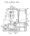
- FIG. 4 is a sectional side view schematically showing the constitution of the conventional circuit breaker, and especially showing the conventional overcurrent tripping device of the circuit breaker.
- the conventional circuit breaker comprises a housing 1 made of a resin.
- the housing 1 consists of a base member 1a and a cover member 1b.
- a conductor 2, whereon a load current flows, is fixed on the base member 1.
- An end 2a of the conductor 2 is connected to a known moving contact mechanism (which is not shown in the figure) and the other end 2b is connected to a terminal member 3.
- a fixed core 4 which has substantially U-letter shaped section in a plane vertical to the paper sheet of FIG. 4, is provided on the conductor 2 for generating a magnetic force by the load current flowing on the conductor 2.
- a bimetal 5 is fixed to the conductor 2 on an end 5a thereof.
- An adjustable screw 6 is provided on the other free end 5b of the bimetal 5 in a manner such that an end 6a of the screw 6 faces to a trip lever 7.
- the trip lever 7 is rotatably borne by a pivot 8.
- An operation arm 9 is rotatably borne by another pivot 11 and has a moving core 10 which is fixed on an end 9b and a pushing part 9a which is formed on the other end 9a for pushing the trip lever 7 when the operation arm 9 rotates in clockwise direction in the figure.
- An extension spring 12 is provided for supplying a rotation force to the operation arm 9 in a direction to make the moving core 10 separate from the fixed core 4.
- Another adjustable screw 13 is provided on a fixed part 14 for adjusting a gap between the fixed core 4 and the moving core 10.
- the above-mentioned pivots 8 and 11 and the fixed part 14 are provided on a frame which is not shown in the figure.
- Tripping operation of the above-mentioned conventional circuit breaker with an overcurrent tripping device is described in the following:
- an overload current which is a little larger than a rated current of the conductor 2 flows, the bimetal 5 warps. Thereby, the end 6a of the screw 6 contacts the trip lever 7.
- the trip lever 7 rotates in clockwise direction in the figure.
- an overload current which is larger than a predetermined value flows on the conductor 2
- the fixed core 4 generates a magnetic attraction force, and the moving core 10 is momentarily attracted to the fixed core 4.
- the operation arm 9 rotates in clockwise direction in the figure.
- the end 9a of the operation lever 9 pushes the trip lever 7.
- US-A-3 3 317 867 shows a circuit breaker with thermal-magnetic tripping allowing for overtravel of the thermal means. From this known circuit breaker the present invention starts from.
- a conductor an end thereof being connected to a moving contact mechanism and the other end being connected to a terminal member.
- a fixed core is provided in the vicinity of said conductor for generating a magnetic attraction force responding to a current value flowing on said conductor.
- a bimetal which warps responding to a current flowing on said conductor for driving a trip member.
- An operation arm is rotatably borne on a holder and has one end facing said fixed core and an action part for actuating said trip member when said operation arm is rotated in a predetermined direction.
- the circuit breaker according to US-A-3 317 867 suffers from a couple of disadvantages: Upon a current value above the normal or rated value of the circuit breaker, the bimetal warps in order to move the latch member so that the contact mechanism is released. If due to a whatsoever reason there still flows a current, the bimetal warps further and the latch member reaches a specific position, thereby resting on an apex between two inclined surfaces of the fixed core. Simultaneously notches of the latch member must slide on lugs against the force of the spring. It is this tilting movement of the latch member, which is the core concept of the invention according to US-A-3 317 867.
- the whole current breaker of US-A-3 317 867 suffers from the disadvantages that there are severe restraints as to the mounting position of the whole circuit breaker in order to not obstruct movement of the notches along the lugs and in order to prevent the latch member falling off the fixed core or its lugs, respectively.
- the whole circuit breaker is furthermore susceptible to vibrations and shocks and its whole operation characteristics are unreliable and unsafe.
- a further disadvantage of the circuit breaker according to US-A-3 317 867 is that there is no predetermined gap between the fixed core and the movable core, which is constituted by the latch member itself. Accordingly, in the latched position the gap between this fixed core and the movable core is - after restoring of the latch member - not always constant and accordingly the tripping values of this known circuit breaker cannot be fixed to a given value in a reliable way.
- the bimetal is carried by the holder; one end of the operation arm facing the fixed core has a moving core for being attracted by the fixed core; and a stopper part is provided at the operation arm for contacting the holder in a manner to keep a predeterminded gap between the fixed core and the moving core when the stopper part contacts the holder, wherein a holder pre-assembly unit is formed by piling up the holder, the fixed core, the conductor, the bimetal and a presser plate in the mentioned order and by fixing them together.
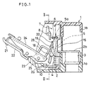
- FIG. 1 is a sectional side view showing a constitution of a main part of the circuit breaker with an overcurrent tripping device in accordance with the present invention.
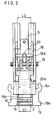
- FIG.2 is a front view showing the constitution of an overcurrent tripping device of the circuit breaker.
- FIG.3 is an exploded perspective view showing the constitution of the assembly unit shown in FIG.2.
- a housing 1 of the circuit breaker consists of a base member 1a and a cover member 1b.
- An end 2a of a conductor 2 is connected to a moving contact mechanism which is described in detail below, and the other end 2b of the conductor 2 is connected to a terminal member 3.
- a fixed core 4 which has substantially U-letter shaped section in a plane vertical to the paper sheet of FIG.1 and generates a magnetic attraction force responding to a current value flowing on the conductor 2, is provided to be fixed on the conductor 2.
- a bimetal 5 is provided to be fixed on the conductor 2 at an end 5b thereof.
- An adjustable screw 6 is provided on the other end Sa of the bimetal 5.
- a trip lever 7 is rotatably borne by a pivot 8.
- the conductor 2, the fixed core 4, the bimetal 5 and so on are mounted on a holder 15, and these elements constitute a holder pre-assembly unit.
- the holder pre-assembly unit is formed by piling-up of the holder 15, the fixed core 4, the conductor 2, the bimetal 5 and a presser plate 16 which has a substantially U-letter shaped section in this order.
- These elements are fixed by caulking of rivets 17 with the presser plate 16.
- the holder 15 has through-holes 15a wherethrough the rivets 17 penetrate and protrusions 15b and 15c which are to be engaged with grooves formed on the base member 1a (not shown in the figure).
- Bracket parts 15d are formed substantially in the center of the holder 15 for bearing an operation arm 18. Stopper parts 15e are formed in the vicinity of the top end for regulating the rotation of the operation arm 18. Furthermore, engaging parts 15f are formed in the vicinity of the top end which is to be engaged with the cover member 1b.
- the operation arm 18 is borne so as to be rotatable on the above-mentioned holder pre-assembly unit via a shaft 19.
- a moving core 10 is fixed on an end 18e of the operation arm 18 in a manner to face the fixed core 4.
- Stopper parts 18a which are to contact the stopper parts 15e of the holder 15 and a pushing part 18b for pushing the trip lever 7 are formed in the vicinity of the other end of the operation arm 18.
- bearing holes 18c wherethrough the shaft 19 penetrates and a spring engaging part 18d whereby a spring 20 is suspended are formed substantially at the center of the operation arm 18.
- An operation arm pre-assembly unit consists of the operation arm 18, the moving core 10 and the like.
- the spring 20 is configured in a double torsion type. Coil parts 20b of the spring 20 are penetrated and held by the shaft 19. Center arm part 20c of the spring 20 is to be engaged with the spring engaging part 18d of the operation arm 18. As shown in FIG.2, both arms 20a of the spring 20 are respectively engaged with the presser plate 16.
- the holder pre-assembly unit, the operation arm pre-assembly unit and the spring 20 are further assembled in one unit, thereby configuring the overcurrent tripping device.
- such overcurrent tripping device is put between the base member 1a and the cover member 1b, and thereby, it is contained in the housing 1 of the circuit breaker.
- the end 2a of the conductor 2 is connected to a flexible conductor 23 of the moving contact mechanism.
- the other end 2b of the conductor 2 is connected to the terminal member 3.
- the moving contact mechanism comprises: a moving contact 21 which is to contact a known stationary contact (not shown in the figure because of being obvious); a moving member 22 which supports the moving contact 21; the flexible conductor 23 which electrically connects the conductor 2 and the moving member 22; a moving contact arm 24 which is rotatably pivoted by a pivot 25; a cross-bar 26 which mechanically connects a plurality of moving contact members and is to be coupled to a known handle (not shown in the figure).
- FIG.1 shows a tripped condition in that the moving contact 23 is separated from the stationary contact (which is not shown in the figure).
- link mechanisms for linking the moving contact mechanism and the trip lever 7, a handle and the like are omitted.
- the operation arm 18 In the circuit breaker with the overcurrent tripping device as configured above, the operation arm 18 always receives a rotation force of the spring 20 in a direction to separate the moving core 10 from the fixed core 4. Since the stopper part 18a of the operation arm 18 contacts the stopper parts 15e of the holder 15, a gap between the fixed core 4 and the moving core 10 is maintained within a predetermined dimension tolerance. Under this condition, when an overload current such as a shortcircuited current, which is above a predetermined value, flows on the conductor 2, the fixed core 4 generates a magnetic attraction force, and thereby the moving core 10 is attracted to the fixed core 4 against the force of the spring 20.
- an overload current such as a shortcircuited current, which is above a predetermined value
- the operation arm 18 starts to rotate, and the pushing part 18b of the operation arm 18 pushes and rotates the trip lever 7.
- the trip lever 7 When the trip lever 7 is rotated, the circuit breaker turns to the tripping state.
- the bimetal 5 warps responding to the temperature rise of the conductor 2. Thereby, the trip lever 7 is rotated by the warped bimetal 5, after passing a predetermined time from the start of the temperature rise.
- the arms 20a-of the spring 20 are respectively engaged with the inner face 16a of the U-letter shaped section of the presser plate 16 (that is, the distance between both arms 20a is kept smaller than the length L1), and the distance is not expanded to the width L2 of the operation arm 18. d Accordingly, the operation arm 18 smoothly moved without any interference of the spring 20.
- the double torsion spring is used as the spring 20.
- a tension spring or a compression spring which is provided between the holder pre-assembly unit and the operation arm pre-assembly unit, can be used for supplying the rotation force of the operation arm pre-assembly unit.
- the torsion spring when used as the spring 20, hooking holes are provided on the conductor 2 or the presser plate 16, and the arms 20a of the spring 20 can be engaged with the hooking holes. Thereby, the distance between both arms 20a can be regulated so as not to interfere the motion of the operation arm pre-assembly unit.
- the fixed core 4 is previously fixed on the holder 15, and the moving core 10 is also previously fixed on the operation arm 18.
- the operation arm 18 is borne on the holder 15 via the shaft 19 before assembling the overcurrent tripping device. Therefore, the gap between the moving core 10 and the fixed core 4 can be adjusted in the predetermined dimension tolerance during the previous assemblage of the operation arm 18 on the holder 15.
- the adjustable screw for adjusting the gap between the fixed core 4 and the moving core 10 which has been necessary in the conventional circuit breaker, is no more need in the circuit breaker in accordance with the present invention.
- the overcurrent tripping device becomes smaller, and thereby, the total size of the circuit breaker also becomes smaller.
- the assemble work of the circuit breaker becomes easy.
Landscapes
- Physics & Mathematics (AREA)
- Electromagnetism (AREA)
- Engineering & Computer Science (AREA)
- Power Engineering (AREA)
- Breakers (AREA)
Claims (5)
- Ein Schutzschalter mit Überstromauslösevorrichtung mit:einem Leiter (2), dessen eines Ende mit einem beweglichen Kontaktmechanismus (24) und dessen anderes Ende mit einem Anschlußteil (3) verbunden ist;einem festen Kern (4), der im Nahbereich des Leiters (2) angeordnet ist, um eine magnetische Anziehungskraft in Antwort auf einen Stromwert zu erzeugen, der in dem Leiter (2) fließt;einem Bimetall (5), welches sich in Antwort auf einen Strom verformt, der in dem Leiter (2) fließt, um ein Auslöseteil (7) anzutreiben; undeinem Betätigungsarm (18), der drehbeweglich an einem Halter (15) gelagert ist und ein Ende aufweist, das dem festen Kern (4) gegenüberliegt und ein Betätigungsteil (18b) aufweist, um das Auslöseteil (7) zu betätigen, wenn der Betätigungsarm (18) in eine bestimmte Richtung gedreht wird,dadurch gekennzeichnet, daßdas Bimetall (5) von dem Halter (15) getragen wird;das eine Ende des Betätigungsarms (18), das dem festen Kern (4) gegenüberliegt, einen beweglichen Kern (10) aufweist zur Anziehung durch den festen Kern (4); undein Anschlagteil (18a) an dem Betätigungsarm (18) angeordnet ist, um den Halter (15) derart zu berühren, daß ein vorherbestimmter Spalt zwischen festem Kern (4) und beweglichem Kern (10) aufrechterhalten wird, wenn das Anschlagteil (18a) den Halter (15) berührt,wobei eine Halter-Vormontageeinheit dadurch gebildet wird, daß der Halter (15), der feste Kern (4), der Leiter (2), das Bimetall (5) und eine Druckplatte (16) in der erwähnten Reihenfolge aneinandergereiht und untereinander befestigt werden.
- Ein Schutzschalter nach Anspruch 1, wobei eine Feder (20) zwischen dem Halter (15) und dem Betätigungsarm (18) angeordnet ist, um eine Drehkraft auf den Betätigungsarm (18) in einer Richtung aufzubringen, in der der bewegliche Kern (10) von dem festen Kern (4) getrennt wird.
- Ein Schutzschalter nach Anspruch 1 oder 2, wobei die Druckplatte (16) einen im wesentlichen U-förmigen Querschnitt hat.
- Ein Schutzschalter nach Anspruch 1, 2 oder 3, wobei eine Betätigungs-Vormontageeinheit durch den Betätigungsarm (18), der drehbeweglich an der Halter-Vormontageeinheit gelagert ist und den beweglichen Kern (10) gebildet wird, der an dem Betätigungsarm (18) befestigt ist.
- Ein Schutzschalter nach einem der vorhergehenden Ansprüche, wobei der Halter (15), der feste Kern (4), der Leiter (2), das Bimetall (5) und eine Druckplatte (16) miteinander durch verstemmen von Nieten (17) mit der Druckplatte (16) verbunden werden.
Applications Claiming Priority (2)
| Application Number | Priority Date | Filing Date | Title |
|---|---|---|---|
| JP144227/92 | 1992-06-04 | ||
| JP4144227A JPH05342967A (ja) | 1992-06-04 | 1992-06-04 | 回路遮断器 |
Publications (2)
| Publication Number | Publication Date |
|---|---|
| EP0572773A1 EP0572773A1 (de) | 1993-12-08 |
| EP0572773B1 true EP0572773B1 (de) | 1997-06-04 |
Family
ID=15357204
Family Applications (1)
| Application Number | Title | Priority Date | Filing Date |
|---|---|---|---|
| EP93104790A Expired - Lifetime EP0572773B1 (de) | 1992-06-04 | 1993-03-23 | Schutzschalter mit Überstromauslösevorrichtung |
Country Status (6)
| Country | Link |
|---|---|
| US (1) | US5329264A (de) |
| EP (1) | EP0572773B1 (de) |
| JP (1) | JPH05342967A (de) |
| KR (1) | KR970007775B1 (de) |
| CN (1) | CN1031434C (de) |
| DE (1) | DE69311205T2 (de) |
Families Citing this family (12)
| Publication number | Priority date | Publication date | Assignee | Title |
|---|---|---|---|---|
| US6259341B1 (en) * | 1999-08-27 | 2001-07-10 | Eaton Corporation | Circuit interrupter with an automatic trip assembly having an improved bimetal configuration |
| KR100474381B1 (ko) * | 2002-08-30 | 2005-03-10 | 엘지산전 주식회사 | 배선용 차단기의 순시트립장치 |
| JP5170657B2 (ja) * | 2008-04-03 | 2013-03-27 | 河村電器産業株式会社 | 過電流引外し機構 |
| FR2943455B1 (fr) * | 2009-03-23 | 2011-05-06 | Hager Electro Sas | Declencheur magnetothermique |
| KR101759594B1 (ko) * | 2011-06-24 | 2017-07-20 | 엘에스산전 주식회사 | 회로차단기 |
| US9601296B2 (en) * | 2012-04-13 | 2017-03-21 | Siemens Industry, Inc. | Low tripping level circuit breakers, tripping units, and methods |
| CN102820182B (zh) * | 2012-08-22 | 2015-07-01 | 温州市新蓝天电器有限公司 | 一种大电流微型断路器 |
| EP2770521B1 (de) * | 2013-02-20 | 2015-10-28 | Siemens Aktiengesellschaft | Thermomagnetische Auslöseeinheit für einen Schutzschalter und Schutzschalter |
| CN104124114B (zh) | 2014-06-24 | 2016-08-24 | 上海诺雅克电气有限公司 | 多极电磁脱扣器的短路保护动作电流调节方法和装置 |
| CN104779127B (zh) * | 2015-04-30 | 2017-05-24 | 德力西电气有限公司 | 可调电磁脱扣器和断路器 |
| CN111886668B (zh) * | 2018-03-23 | 2023-03-10 | 三菱电机株式会社 | 跳闸装置 |
| JP6945499B2 (ja) * | 2018-05-31 | 2021-10-06 | 三菱電機株式会社 | 回路遮断器 |
Family Cites Families (10)
| Publication number | Priority date | Publication date | Assignee | Title |
|---|---|---|---|---|
| US2902560A (en) * | 1955-05-18 | 1959-09-01 | Square D Co | Circuit breaker |
| US3264435A (en) * | 1962-06-25 | 1966-08-02 | Gen Electric | Circuit breaker with removable trip unit having improved mounting means for terminal strap and thermal responsive means |
| US3305653A (en) * | 1965-06-21 | 1967-02-21 | Ite Circuit Breaker Ltd | Circuit breaker trip assembly with increased compensation for misalignment |
| US3317867A (en) * | 1965-12-13 | 1967-05-02 | Gen Electric | Electric circuit breaker with thermalmagnetic tripping allowing for overtravel of the thermal means |
| DE1588507B2 (de) * | 1967-12-12 | 1971-06-03 | Licentia Patent Verwaltungs GmbH, 6000 Frankfurt | Kombinierter bimetall und magnetausloeser |
| FR2261615B1 (de) * | 1974-02-20 | 1978-12-01 | Unelec | |
| US4074218A (en) * | 1976-05-07 | 1978-02-14 | Westinghouse Electric Corporation | Circuit breaker |
| US4503408A (en) * | 1982-11-10 | 1985-03-05 | Westinghouse Electric Corp. | Molded case circuit breaker apparatus having trip bar with flexible armature interconnection |
| US4691182A (en) * | 1986-04-30 | 1987-09-01 | Westinghouse Electric Corp. | Circuit breaker with adjustable magnetic trip unit |
| JPH0319236A (ja) * | 1989-06-15 | 1991-01-28 | Matsushita Electron Corp | バイポーラ型トランジスタ |
-
1992
- 1992-06-04 JP JP4144227A patent/JPH05342967A/ja active Pending
- 1992-12-28 KR KR1019920025747A patent/KR970007775B1/ko not_active Expired - Fee Related
-
1993
- 1993-03-23 EP EP93104790A patent/EP0572773B1/de not_active Expired - Lifetime
- 1993-03-23 DE DE69311205T patent/DE69311205T2/de not_active Expired - Fee Related
- 1993-03-25 US US08/043,469 patent/US5329264A/en not_active Expired - Fee Related
- 1993-05-28 CN CN93106572A patent/CN1031434C/zh not_active Expired - Fee Related
Also Published As
| Publication number | Publication date |
|---|---|
| HK1006760A1 (en) | 1999-03-12 |
| EP0572773A1 (de) | 1993-12-08 |
| JPH05342967A (ja) | 1993-12-24 |
| US5329264A (en) | 1994-07-12 |
| CN1087748A (zh) | 1994-06-08 |
| DE69311205T2 (de) | 1997-10-30 |
| CN1031434C (zh) | 1996-03-27 |
| DE69311205D1 (de) | 1997-07-10 |
| KR940001216A (ko) | 1994-01-11 |
| KR970007775B1 (ko) | 1997-05-16 |
Similar Documents
| Publication | Publication Date | Title |
|---|---|---|
| EP0572773B1 (de) | Schutzschalter mit Überstromauslösevorrichtung | |
| US5223813A (en) | Circuit breaker rocker actuator switch | |
| EP0111140B1 (de) | Selbstschalter mit Gussgehäuse und mit flexibel mit einem Anker verbundener Auslösewelle | |
| US4622530A (en) | Circuit breaker assembly for high speed manufacture | |
| JPH04500744A (ja) | 回路遮断器用単体遮断器組立体 | |
| JPS634530A (ja) | 回路遮断器 | |
| US5097589A (en) | Method of manufacturing a circuit breaker | |
| US4546336A (en) | Residential circuit breaker with combination slot motor and arc chute | |
| US3288965A (en) | Multiple circuit breaker assembly with common tripping | |
| AU721606B2 (en) | Roller latching and release mechanism for electrical switching apparatus | |
| US5173674A (en) | Thermal-magnetic trip unit with low current response | |
| US4546337A (en) | Residential circuit breaker with one piece slot motor | |
| US5285180A (en) | Circuit breaker | |
| HK1006760B (en) | Circuit breaker with overcurrent tripping device | |
| JP2505011B2 (ja) | 回路遮断器の電磁装置 | |
| US5237297A (en) | Tripping apparatus for use with an electrical circuit breaker having magnetic tripping responsive to low overcurrent | |
| US2934620A (en) | Circuit breaker | |
| US4799037A (en) | Circuit interrupter | |
| US4521756A (en) | Circuit breaker having increased contact opening velocity at trip operation | |
| JPS6340228A (ja) | 回路しや断器 | |
| EP0020311B1 (de) | Auslösezunge für einpolige Schutzschalter | |
| JPH0220747Y2 (de) | ||
| JPS6326908Y2 (de) | ||
| US4794357A (en) | Multi-pole circuit interrupter | |
| JPS6325647Y2 (de) |
Legal Events
| Date | Code | Title | Description |
|---|---|---|---|
| PUAI | Public reference made under article 153(3) epc to a published international application that has entered the european phase |
Free format text: ORIGINAL CODE: 0009012 |
|
| AK | Designated contracting states |
Kind code of ref document: A1 Designated state(s): DE FR GB NL |
|
| 17P | Request for examination filed |
Effective date: 19940314 |
|
| 17Q | First examination report despatched |
Effective date: 19950612 |
|
| GRAG | Despatch of communication of intention to grant |
Free format text: ORIGINAL CODE: EPIDOS AGRA |
|
| GRAH | Despatch of communication of intention to grant a patent |
Free format text: ORIGINAL CODE: EPIDOS IGRA |
|
| GRAH | Despatch of communication of intention to grant a patent |
Free format text: ORIGINAL CODE: EPIDOS IGRA |
|
| GRAA | (expected) grant |
Free format text: ORIGINAL CODE: 0009210 |
|
| AK | Designated contracting states |
Kind code of ref document: B1 Designated state(s): DE FR GB NL |
|
| REF | Corresponds to: |
Ref document number: 69311205 Country of ref document: DE Date of ref document: 19970710 |
|
| ET | Fr: translation filed | ||
| PLBE | No opposition filed within time limit |
Free format text: ORIGINAL CODE: 0009261 |
|
| 26N | No opposition filed | ||
| PGFP | Annual fee paid to national office [announced via postgrant information from national office to epo] |
Ref country code: NL Payment date: 19990329 Year of fee payment: 7 |
|
| REG | Reference to a national code |
Ref country code: GB Ref legal event code: 746 Effective date: 19990519 |
|
| REG | Reference to a national code |
Ref country code: FR Ref legal event code: D6 |
|
| PG25 | Lapsed in a contracting state [announced via postgrant information from national office to epo] |
Ref country code: NL Free format text: LAPSE BECAUSE OF NON-PAYMENT OF DUE FEES Effective date: 20001001 |
|
| NLV4 | Nl: lapsed or anulled due to non-payment of the annual fee |
Effective date: 20001001 |
|
| REG | Reference to a national code |
Ref country code: GB Ref legal event code: IF02 |
|
| PGFP | Annual fee paid to national office [announced via postgrant information from national office to epo] |
Ref country code: FR Payment date: 20020312 Year of fee payment: 10 |
|
| PGFP | Annual fee paid to national office [announced via postgrant information from national office to epo] |
Ref country code: GB Payment date: 20020327 Year of fee payment: 10 |
|
| PGFP | Annual fee paid to national office [announced via postgrant information from national office to epo] |
Ref country code: DE Payment date: 20020404 Year of fee payment: 10 |
|
| PG25 | Lapsed in a contracting state [announced via postgrant information from national office to epo] |
Ref country code: GB Free format text: LAPSE BECAUSE OF NON-PAYMENT OF DUE FEES Effective date: 20030323 |
|
| PG25 | Lapsed in a contracting state [announced via postgrant information from national office to epo] |
Ref country code: DE Free format text: LAPSE BECAUSE OF NON-PAYMENT OF DUE FEES Effective date: 20031001 |
|
| GBPC | Gb: european patent ceased through non-payment of renewal fee |
Effective date: 20030323 |
|
| PG25 | Lapsed in a contracting state [announced via postgrant information from national office to epo] |
Ref country code: FR Free format text: LAPSE BECAUSE OF NON-PAYMENT OF DUE FEES Effective date: 20031127 |
|
| REG | Reference to a national code |
Ref country code: FR Ref legal event code: ST |