EP0572538B1 - Holographisches aufnahme- und abtastsystem und methode - Google Patents
Holographisches aufnahme- und abtastsystem und methode Download PDFInfo
- Publication number
- EP0572538B1 EP0572538B1 EP92907363A EP92907363A EP0572538B1 EP 0572538 B1 EP0572538 B1 EP 0572538B1 EP 92907363 A EP92907363 A EP 92907363A EP 92907363 A EP92907363 A EP 92907363A EP 0572538 B1 EP0572538 B1 EP 0572538B1
- Authority
- EP
- European Patent Office
- Prior art keywords
- hologram
- scan
- light beam
- disk
- post
- Prior art date
- Legal status (The legal status is an assumption and is not a legal conclusion. Google has not performed a legal analysis and makes no representation as to the accuracy of the status listed.)
- Expired - Lifetime
Links
Images


Classifications
-
- G—PHYSICS
- G02—OPTICS
- G02B—OPTICAL ELEMENTS, SYSTEMS OR APPARATUS
- G02B26/00—Optical devices or arrangements for the control of light using movable or deformable optical elements
- G02B26/08—Optical devices or arrangements for the control of light using movable or deformable optical elements for controlling the direction of light
- G02B26/10—Scanning systems
- G02B26/106—Scanning systems having diffraction gratings as scanning elements, e.g. holographic scanners
Definitions
- This invention relates to holographic recording and scanner systems and specifically to a holographic scanner which is both less expensive and at least as accurate as prior art holographic scanning systems.
- U.S. Patent 4,753,503 discloses a laser scanning system utilizing a laser beam conditioned to provide proper beam shape prior to the passage of the beam through a diffraction grating on a rotating holographic disc. Mirrors and similar optics allow the laser beam to be scanned along a straight line on a rotating drum for the recording of information.
- the system of the '503 patent uses a solid-state laser diode 11 together with collecting lens 12 to collect and collimate the output light from diode 11.
- the processed laser beam is then deflected by a holographic scanner consisting of a rotating disc with a plurality of diffraction gratings formed thereon to produce a rotating diffracted beam which is used to store information on a photoconductive surface.
- the system of the '503 patent uses optics to process the beam produced by the laser diode to ensure that the processed beam has the appropriate characteristics for use in generating a scan line on the photoconducting surface of the recording drum.
- the optics add cost to the scanning system.
- a holographic and recording scanning system which overcomes certain of the disadvantages of the prior art.
- the holographic scanning system of this invention eliminates certain optical components previously required in prior art scanners thereby significantly reducing the cost of the system.
- the holographic scanning system of this invention is substantially less sensitive to disc wobble and variation in the frequency of the monochromatic light source than are prior art systems.
- This invention provides a structure which makes use of a recording geometry in which no significant Seidel induced aberrations arise.
- the recording geometry comprises a first point source monochromatic object beam and a second point source coherent with the object beam source.
- the object and reference beams interfere to produce a pattern recorded on a photosensitive surface, thereby creating the pattern from which the hologram on the scanning disc is created.
- Reconstruction of the object is made by exposing the scanning disc to substantially monochromatic light from a point source generated by any commercially available laser diode at the same or different frequency. This enables reconstruction at a different wavelength, i.e., in the range of 700-1000 nm which is typical of low-cost laser diodes, than what is used for recording the hologram.
- One or two hologram surfaces can be used in this reconstruction.
- the hologram on the scanning disc not only directs the reconstruction beam, but also focuses it. Further, the reconstruction beam is at a large enough angle to the scanning disc to insure all diffracted light goes into one first order.
- a curved mirror which creates nearly equal optical path length increments for each equal angular increment of rotation of the scanning disc, can be used.
- This mirror corrects for bow or curvature of the scan line, and ensures linearity.
- the curved mirror also optimizes flatness of the focal plane. Disc wobble is minimized by insuring that the incident angle of the reconstruction beam to the scanning disc is equivalent to the diffraction angle.
- This invention provides a structure for achromatization, or correction of beam placement because of mode hops or drift in laser frequency.
- This structure corrects for both in-scan change, (i.e., the change in the focal point along the line of scan), and cross-scan change, (i.e., the change in the focal point perpendicular to the line of scan).
- In-scan correction of beam position as a function of change in beam wavelength can be done by two methods.
- a pre-scan hologram can be used so that its spatial frequency provides an angular dispersion of the amount required to move the beam to the correct position on the scanning disc.
- a second method uses a prism as a dispersive element to move the system aperture (i.e., the spot of light incident on the scanning disc) along the scanning disc radius with subsequent wavelength changes to achieve in-scan correction.
- Cross-scan correction is accomplished with a post-scan hologram (i.e., a hologram placed in the optical path after the scanning disc).
- This correction comprises placing a hologram near the focal plane which creates an astigmatic beam, i.e., a beam that is unable to form approximately point images.
- Three methods are disclosed to correct the astigmatism.
- an optical element with an astigmatism is placed near the scanning disc to substantially cancel the astigmatism created by the post-scan hologram.
- the second method comprises using a radially symmetric laser collimator which emits an astigmatic beam. Once again, the astigmatic beam corrects for the astigmatism produced by the post-scan hologram.
- the third method involves the adjustment of the degree of astigmatism specified for in the collimator lens, together with the degree of natural astigmatism in a typical laser diode, in order to substantially cancel the astigmatism created by the post-scan hologram.
- the pre-scan hologram is removed and the post-scan hologram is moved closer to the focal plane.
- the astigmatism created by the post-scan hologram is corrected by an optical element placed before the post-scan hologram which serves the same function as the pre-scan hologram.
- the position of the system aperture is adjusted with an aperture mask to control the shape of the beam cross-section.
- Recording of the post-scan hologram is achieved with a plurality of lenses which possess different collimating properties in the vertical and horizontal planes.
- a scanning disc may be replicated on various transparent materials.
- this invention provides a structure which allows for a commercially viable holographic optical system.
- This system offers significant cost savings over other systems because of its use of inexpensive laser diodes and the replacement of expensive optical lenses which are generally used in a conventional system with holographic surfaces which focus and correct the beam.
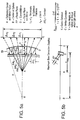
- Figs. 1a and 1b illustrate a prior art method of recording a hologram wherein reconstruction is made by exposing the recorded hologram to a collimated light source at normal incidence.
- Figs. 2a and 2b show two embodiments of the present invention which use a spherical wave of light originating from a point source as a reconstruction beam.
- Fig. 3 illustrates one example of the recording geometry that would allow reconstruction of the object with a point source of light and a coherent virtual point source.
- Fig. 4a shows a bow in the reconstruction beam which is produced by deflector hologram recording geometry.
- Fig. 4b illustrates the inclusion of a curved mirror to correct for bow in the scan line.
- Fig. 4c illustrates a detailed geometry used to eliminate bow.
- Fig. 5a illustrates a structure for obtaining bow correction, linearity, and a flat field.
- Fig. 5b illustrates the structure and equation to obtain maximum bow correction.
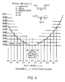
- Fig. 6 shows a plot of diffraction angles for a range of wobble angles.
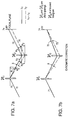
- Fig. 7a shows a light ray diffracted by two holograms of the same spatial frequency in series.
- Fig. 7b shows a light ray diffracted by two holograms where the second hologram focuses the light in order to reduce cross-scan chromatic error.
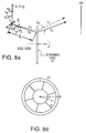
- Fig. 8a illustrates irregular scan lines which produce in-scan dot placement errors.
- Fig. 8b shows a top view of a portion of the scanner system without an in-scan corrector.
- Fig. 8c shows a top view of a portion of the scanner system with an in-scan corrector.
- Fig. 8d shows a plan view of the facets on the scanning disc.
- Fig. 9 illustrates one embodiment of the present invention which includes correction of cross-scan errors by placing a hologram near the focal plane.
- Fig. 10 illustrates another embodiment which includes an in-scan correction hologram.
- Fig. 11a shows a light beam being focused onto a focal plane without a cross-scan corrector or an optical element.
- Fig. 11b shows the effect of the cross-scan corrector on the light beam.
- Fig. 11c shows the effect of an optical element with the cross-scan corrector which changes the focal plane.
- Fig. 12a comprises a configuration for recording the post-scan hologram, i.e., cross-scan corrector.
- Fig. 12b shows a side view of the reference path of Fig. 12a.
- Fig. 13 illustrates a side view of the object path of Fig. 12a.
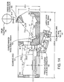
- Fig. 14 shows a side view of an actual embodiment of the present invention.
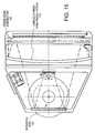
- Fig. 15 shows a top view of an actual embodiment of the present invention.
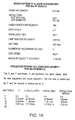
- Fig. 16 illustrates the specifications and deflection errors including bow and linearity for a 300 DPI (i.e., dots per inch) module of the type shown in Figs. 15 and 16.
- 300 DPI i.e., dots per inch
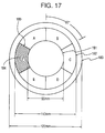
- Fig. 17 shows an actual embodiment of the scanning disc with six facets.
- the prior art makes use of a pre-scan hologram which produces a wave-front aberration of approximately the same shape but of opposite curvature as the aberration function of the holograms on the scanning disc.
- the object is to cancel the Seidel induced aberrations which include: spherical aberrations, blurring of the image when parallel light is incident on a spherical mirror; coma, a comet-like appearance of an image of an object point located just off the lens axis; and astigmatism, a difference in focal length for rays coming in different planes from an off-axis object. Seidel aberrations are discussed in more detail by F. Jenkins and H. White in Fundamentals of Optics , 151-171 (1976).
- One means for aberration correction is a system which makes use of a recording geometry in which no significant aberration arises. This system avoids the cost associated with precise aberrated wave front alignment and curvature matching.
- a principle used in this system for recording wavelength ⁇ 1 , (for example 441.6 nm) and readout at ⁇ 2 (780 nm) without aberrations is described by Clay in the Handbook of Optical Holography, 441-444 (1979). The recording parameters are calculated from considerations of the desired readout geometry and wavelength shift between recording and readout.
- the recording geometry comprises a first point source 12 of monochromatic light as the object beam 12a and a second point source 10 of monochromatic light as the reference beam 10a in which the first and second points lie on a straight line perpendicular to the hologram plane 11.
- a photosensitive surface comprised of Shipley Microposit 1400-37. Other comparable photoresists can also be used.
- the object beam 12a and reference beam 10a create interference fringes, i.e., regions of alternating bright and dark intensity, that are recorded on a layer of photosensitive material the surface of which is the hologram plane 11.
- this hologram on scanning disc 11a is illuminated by a collimated monochromatic light beam 13 at normal incidence to the disc in order to reconstruct the object.
- Holograms as recorded above have yielded reconstructed images free from chromatically induced Seidel aberrations over a frequency shift of more than an octave. (Diffraction limits the operation for an object consisting of an array of 11 x 11 dots covering a detector array of 11 x 11 elements with overall dimension of 6.5 x 6.5 mm. Clay, supra, at 443. However, only one dot is reconstructed here.)
- Figs. 2a and 2b show that the readout beam is no longer a collimated beam. Instead, there is a spherical wave 21 originating from p 1 such that p 1 and p 2 are at equal conjugates, i.e., p 1 and p 2 are at equal distance from the holographic plane(s).
- the recording medium is placed on both sides of the substrate 20 whereby identical holograms and are recorded on both sides.
- the beam is collimated in the space between the two hologram surfaces, i.e., within the substrate 20.
- Fig. 2b shows a layout conforming to this requirement.
- a transmission grating is used.
- a transmission grating is a diffraction grating with many fringes in it. The depth of the fringes is the groove height. The distance between midpoints of two grooves is the grating constant.
- Fig. 3 illustrates the relative locations of the monochromatic beams and the holographic surface for recording the scanning disc Fig. 3 further illustrates that it is unnecessary for the point source 31 of the object beam and the point source 30 of the reference beam to be located in a straight line perpendicular to the hologram plane
- a curved mirror 40 is added as shown in Figs. 4a and 4b.
- the curved mirror 40 in one implementation, is a cylindrical curved mirror which has no power in the cross-scan direction. Hence, other system components would have to be adjusted to provide the necessary power in the cross-scan direction.
- the preferred embodiment comprises a two dimensional curved oblate spheroid mirror. This mirror's curvature is determined by solving for the vertex curvature C in the equation below.
- Z sag CY 2 1+ 1-( K +1) C 2 Y 2
- K is the conic constant
- Y is the zone height, i.e., radius on the lens at which light strikes it
- Z sag is the mirror's sagitta of arc. See Figs. 5a and 5b.
- Its position and curvature make the system approximately telecentric, i.e., when the axis of the scan beam is everywhere normal to the focal plane.
- the scan line curvature is affected by the angular incidence of the beam 41 on the mirror 40, which allows adjustment of the bow 42 at the focal plane 43 without significantly affecting the system's telecentricity. This adjustment yields a very straight line for a line length of 216 mm (8.5 in) as the bow is only 4 micrometers (four parts in 216,000 or .00185%).
- a plane triangular fan of light A-0"-0' is placed with its apex on a normal to the center of the mirror 40 and at a distance of one half a radius R from the mirror vertex, or point of greatest curvature on the mirror. (Note: point A is located on the scanning disc which is not shown in Fig. 4b. Point A also indicates where the apex of the fan of light is placed.) That fan of light will be reflected as a parallel-sided plane sheet of light having the width of the intercept distance EE', i.e., the mirror of radius R collimates the fan of light where the fan is the envelope of the scanned beam and the deflection center is at A.
- the depth of bow (sagitta of arc, or distance from the mid-point of an arc to the mid-point of its cord) is a function of the angle of incidence and of the radius of the mirror. The direction of the bow will depend on the direction of incidence.
- the input fan of light is bowed, then at some angle of incidence other than zero the reflected sheet of light can be made plane by adjusting the mirror angle.
- the curved mirror 40 (which is approximately spherical), can be angularly adjusted to bring about a change in incidence, resulting in a correction of the bowed line. If the curvature of the mirror is made less, then the incidence deviation must increase to accommodate the correction. However, for the spot of light to travel in equal length intervals on the focal plane for equal time intervals, a specific curvature, as described more fully below, is disclosed.
- Fig. 4b the rotor 44 which is connected to scanning disc 45 travels at a constant angular velocity and, therefore, scanning disc 45 deflects the beam 41 in equal increments with time.
- Fig. 5a shows that the line is scanned in unequal length increments with time starting with ⁇ 1 where ⁇ X 1 is the length of the line segment.
- the goal of a f- ⁇ lens is to perform in this way, but the effect is imperfect.
- the distortion curve produced by the f- ⁇ lens does not quite fit the required error curve for the system.
- the f- ⁇ lens can change the amplitude, but cannot exactly match the shape of the curve.
- a spherical mirror segment D as shown in Figs. 5a and 5b, more accurately creates the desired curve. Additionally, the spherical mirror D is much cheaper than an f- ⁇ lens.
- This correction is valid for small fields-of-view.
- an aspheric surface is used.
- the actual surface to be written on, or focal plane FP is a straight line element on a drum or in some cases a photoreceptor having a planar surface.
- the curved mirror D eliminates the problem of the f- ⁇ lens which tends to enlarge the focused spot near the edge of the field.
- the curved mirror corrects bow and linearity while producing a flat field.
- the scanning disc is positioned at the angle of minimum deviation to eliminate dot position errors caused by the wobble of the rotating disc. This necessitates that the incident angle ⁇ equals the diffraction angle ⁇ .
- the wobble angle ⁇ at any instant changes the input to ⁇ ⁇ ⁇ and the output to that shown as plotted in Fig. 6.
- Fig. 6 shows that for a specified shaft wobble of 1.0 degree, the output angle shifts by 0.0004 degrees for a mean deflection of 30 degrees.
- the dot position error on a scan line then varies 4 microns for a system having a focal length of 480 mm.
- the spatial frequency used in this example is 1282.05 cycles per millimeter.
- Diffraction gratings have a wavelength dispersion which is directly proportional to their spatial frequency (i.e., 1 / d where d is the distance between fringes). Therefore, a hologram used to deflect a beam a specified amount for a given input wavelength will do so only at that wavelength. A change in wavelength will cause a change in deflection resulting in a beam position error.
- Fig. 7a shows a ray 70 diffracted by two holograms in series and of the same spatial frequency.
- Figs. 8a and 8b show that the length of a scan line W 2 will be greater for ⁇ 2 than for ⁇ 1 with scant line W 1 , where ⁇ 2 > ⁇ 1 . Hence, a separate means must be found to correct for in-scan dot placement errors.
- the pre-scan hologram could provide correction for in-scan errors. But since the fringe field is generally distorted, the ability to correct for in-scan errors is compromised. Precise alignment to the deflector in x, y, z and ⁇ (rotation of a hologram about its normal axis) is required to obtain a null.
- Fig. 8a shows a pre-scan hologram 80 (hereinafter the in-scan corrector), which is a plane, constant frequency linear grating, oriented to increase rather than decrease the dispersion angle difference.
- the in-scan corrector is a plane, constant frequency linear grating, oriented to increase rather than decrease the dispersion angle difference.
- Increasing the dispersion angle occurs when in-scan corrector 80 is not parallel to the scanning disc 81. This orientation will be discussed in more detail below.
- the in-scan corrector actually worsens cross-scan correction.
- This in-scan corrector 80 behaves in a way that takes advantage of the distortion of the scanning disc which creates greater magnification at the borders of the reconstructed object, i.e., pincushion distortion.
- the effective system aperture i.e., the illuminated spot on the scanning disc which is produced by the light beam from the source being diffracted by the in-scan corrector
- the effective system aperture is moved toward the center of the scanning disc 81 by a changing wavelength
- the angular change in incidence on the scanning disc 81 causes the length of the scan line to be minimized.
- the effective system aperture is moved toward the periphery of the in-scan corrector 80, the scan line is lengthened.
- this movement increases bow (bow is treated as a separate problem and is dealt with in preceding paragraphs).
- the in-scan corrector 80 provides the means of positioning the system's aperture on the scanning disc 81. Therefore, the angle from the source 81, i.e., laser or collimator lens to the scanning disc varies as a function of wavelength. A longer wavelength, such as ⁇ 2 , causes the in-scan corrector 80 to diffract the beam through a greater angle and consequently toward the center of the scanning disc 81.
- Figs. 8a, b, c show these effects. As seen in Fig.
- r l tan ⁇ 1 where l is the distance from the in-scan corrector to the facet A on scanning disc 81.
- ⁇ 1 sin ⁇ + sin ⁇ ⁇ where ⁇ is the angle of incidence, ⁇ is the angle of diffraction, and ⁇ 1 is the spatial frequency of the hologram.
- correction for in-scan error is achieved by providing an in-scan corrector having a spatial frequency yielding an angular dispersion of the amount required to move the beam to the correct position on the disc, thereby achieving a constant line-length.
- the in-scan corrector is 30 mm from the scanning disc, as seen in an actual embodiment of the present invention in Fig. 14, then the input and output angle is 31.5°, thereby creating a spatial frequency equal to 1339.7 cycles per millimeter.
- Another embodiment makes use of a prism (not shown) as a dispersive element, rather than the in-scan corrector, to move the system aperture along the disc radius with subsequent wavelength change.
- a prism (not shown) as a dispersive element, rather than the in-scan corrector, to move the system aperture along the disc radius with subsequent wavelength change.
- the use of a prism is less accurate because the dispersion of a prism is a function of wavelength, and therefore, beam displacement is non-linear. For very small wavelength changes, the non-linearity of the prism correction would not be a problem.
- a diffraction grating on an in-scan corrector has a constant dispersion and the beam displacement is linear. Additionally, in-scan correctors cost less than prisms. Therefore, because of both flexibility and cost, most embodiments of the present invention include holographic in-scan correctors.
- Cross-scan errors may also be corrected by placing post-scan holograms 91 and 101 (hereinafter the cross-scan correctors) near the focal plane, as seen in Figs. 9 and 10, respectively.
- These cross-scan correctors have power in the cross-scan, but not in the in-scan meridian. Their effects are similar to a cylinder with the zero power axis parallel to the scan line.
- the cross-scan corrector, 91 or 101 has a dispersive component which diffracts the beam.
- the cross-scan corrector is positioned to cause the light, as a result of this component addition, to fall at normal incidence on the focal plane (92 or 102 of Figs. 9 and 10, respectively).
- the beam is now astigmatic, i.e., the focal plane for the cross-scan meridian is not coincident with that of the in-scan meridian.
- three alternative solutions are possible.
- an optical element 95 or 105 can be placed near the scanning disc, as in Figs. 9 and 10, respectively.
- this optical element 115 has positive cylindrical power which introduces an astigmatism which corrects for the astigmatism created by the cross-scan corrector 111.
- f 1 is the focal length of the astigmatic component in the system before the optical element
- f 2 is the focal length of the optical element
- f is focal length of the combination of f 1 and f 2 .
- the sum of this cylindrical power and the power of the cross-scan corrector brings the two focal planes, FP 1 and FP 2 , of the cross-scan and in-scan meridian into coincidence.
- collimators 94 and 104 in Figures 9 and 10 are, in general, not circularly symmetric but contain a cylindrical component to accommodate the radiation pattern from the laser diode of this class.
- the radiation pattern is characterized by an angle of about 20 degrees in one meridian and about 30 degrees in the orthogonal meridian resulting in an elliptical beam cross-section. Since optical systems, in general, must have circular cross-section input beams, then a means for converting this ellipse to a circle is necessary.
- this conversion means comprise either a cylindrical component placed in the collimator or a pair of prisms mounted therein.
- this invention can make use of an uncorrected beam, i.e., an astigmatic beam emerging from an uncorrected collimator. Since the laser beam is already astigmatic, this becomes an advantage; the laser is mounted so that the elliptical emergent beam cross-section is oriented in a direction to provide the required astigmatism for substantially reducing that caused by the cross-scan corrector. Specifically, the laser is turned so that the emerging ellipse has its major axis along the groove direction.
- the degree of astigmatism can be adjusted to cancel that produced by the cross-scan corrector.
- the adjustment involves the degree of astigmatism correction specified for in the collimator lens, together with the degree of natural astigmatism in the laser. This is desirable since it enables the system to use different laser types having different amounts of astigmatism.
- the in-scan corrector is removed and the cross-scan corrector 91 is moved to a position of greater proximity to the focal plane 92.
- the cross-scan corrector acts in a manner similar to a cylindrical lens of zero power in the in-scan meridian and strong power (for example, 30 diopters) in the cross-scan meridian. Placing the cross-scan corrector at about 21 mm or less from the focal plane 92 eliminates cross-scan errors and reduces the dot dimension in the vertical direction, but not in the orthogonal direction.
- the dot shape can be corrected by the introduction of astigmatism with the use of a cylinder 95 as previously mentioned, and/or by adjusting the system aperture shape with an aperture mask 96 so that the Numerical Aperture (NA) is made smaller in the cross-scan meridian.
- the aperture mask can be fabricated out of any opaque or relatively opaque material common in the industry.
- the cross-scan corrector 91 images the deflector aperture, i.e., the aperture of aperture mask 96, on the focal plane 92.
- This implementation can be used in those applications in which some in-scan error can be tolerated, but not in very high resolution systems, such as those requiring 900 to 1200 dots per inch where in-scan errors are usually specified to be on the order of 1/4 to 1/2 dot.
- Fig. 12a The configuration for recording the cross-scan corrector is shown in Fig. 12a.
- a beam splitter splits this light beam into two beams. One beam becomes the reference beam 121.
- the second beam becomes the object beam 123.
- the reference beam 121 is expanded by the microscope objective L R to fill lens L 1 .
- the reference beam 121 is collimated in both the vertical and horizontal planes by lens L 1 and L 2 . In this way, light is conserved.
- Fig. 12b shows a side view of the reference beam.
- the width and height of lenses L 1 and L 2 are determined by the size of the hologram 122 to be recorded.
- the object beam 123 is in a path containing lenses L 3 and L 4 which produce a collimated beam in the horizontal plane but only L 4 produces a collimated beam in the vertical plane.
- L 5 focuses the collimated light to a line focus at a distance of Z R from the hologram. After Z R , the beam then expands in the horizontal plane, but remains collimated in the vertical plane.
- the fringe pattern produced on the hologram 122 has a Fresnel distribution, i.e., higher spatial frequency at the edge fringes than at the middle, in the horizontal plane and has straight fringes in the vertical direction.
- Z n is the focal length of lens L 3 .
- the focal length of L 4 is Z s and that of L 5 is Z t .
- the pre-deflection hologram is a plane constant frequency grating, ordinary standard procedures are used in its recording.
- Figs. 9 and 10 show the layout of the complete system showing the correctors.
- the optical element 95 or 105 is oriented so that its dispersive power subtracts from the system dispersion error.
- Fig. 10 illustrates the principle ray paths P 1 , P 2 , P 3 as a function of different wavelengths.
- the focal plane In the absence of optical element 111, the focal plane, as shown in Fig. lla, is positioned at FP 1 .
- FP 1 is a property of the uncorrected system.
- a second focal plane is at FP 2 .
- Optical element 111 has a positive cylindrical power and is inserted at a distance l 1 from focal plane FP 1 .
- One embodiment of this invention uses a cylinder for an optical element. The power of cylinder 111 results in convergance of the rays on FP 2 , but only in the power meridian. The rays in the cylinder's zero power are still converged at FP 1 .
- these focal planes FP 1 and FP 2 should coincide.
- the distance between FP 1 and FP 2 is approximately equal to the focal length f cy of cylinder 111.
- f cy ⁇ l 1 - l 2 .
- the actual distance is modified slightly because of the original power of the system before the cylinder, but this original power is negligible in comparison with f cy and therefore does not affect the separation of the two planes.
- an elliptical spot is needed. With an elliptical spot, the major axis is vertical and slightly larger than the line interval to ensure that no white paper will show through when black multiple horizontal lines are written.
- the minor axis dimension is made less than the horizontal dot interval so that vertical lines of smaller thickness than a dot width may be written. Thicker lines require longer "on times", which is a software function.
- Figs. 14 and 15 illustrate an actual scanning system which embodies the present invention.
- an index-guided laser diode 140 puts out 5 mW of power and emits light at a wavelength of approximately 780 nm which is collimated by collimating lens 141.
- This collimator lens has a focal length of 9 mm and has a Numerical Aperture of 0.25.
- This collimation beam is defocused slightly giving rise to a curved rather than a plane wavefront. This is done to satisfy the need for a finite distance virtual point source.
- This reconstruction beam is then diffracted by the in-scan corrector 146 to pass through the spinning scanning disc 142.
- Scanning disc 142 diffracts and focuses the light beam. This light beam is then reflected off a series of folding mirrors M 1 , M 2 , and M 3 which serve to make the scanning system as compact as possible. Mirrors M 1 , M 2 , and M 3 are all plane flat mirrors. After reflection off M 3 , the light beam is reflected off curved mirror 143 5 which has a vertex radius of 645 mm onto the cross-scan corrector 144. Referring back to Figs. 12a, 12b, and 12c, the cross-scan corrector was recorded with the following paramters.
- L R is a microscope objective of 40x with a focal length of 4 millimeters.
- the angle ⁇ formed by the reference and object path is 27.2 degrees.
- L o is a microscope objective of 40x with a focal length of 4 millimeters.
- L 3 is a lens with a focal length of 15.24 millimeters, while L 4 has a focal length of 500 millimeters.
- the dimension of the beam from L 3 to L 4 is 7.62 millimeters.
- L 5 is a lens with a focal length of 80 millimeters.
- Z T as seen in Fig. 13, is 80 millimeters and Z R is 272 millimeters. The distance between L 4 and L 5 does not affect the invention because the beam is parallel in both planes.
- Z P is 500 millimeters.
- L 1 has a focal length of 50 millimeters while L 2 has a focal length of 500 millimeters.
- Using the preceding parameters yields a hologram with a spatial frequency of 1035 cycles per millimeter in the center. This cross-scan corrector diffracts the beam onto focal plan 145. All distances illustrated in Figs. 14 and 15 are in millimeters.
- Fig. 16 lists the specifications for a 300 DPI module and deflection errors including bow and linearity.
- holograms can be replicated on plastic which further reduces the cost of the scanning system.
- the holograms can be replicated on a thin transparent plastic with a diameter and thickness comparable to the substrate of a compact audio disc. While the dimensions of a compact disc are satisfactory, they represent one of many possible implementations, e.g., the disc may be thin such as a floppy disc. The diameter is not confined to 5 inches but may be sized according to the application--from 1 inch in diameter to 10 inches in diameter. The thickness of the disc may be varied to suit the application. Additionally, the substrate material may be virtually any transparent material such as glass, plastic, etc.
- the process of replicating a hologram comprises the following steps.
- embossing Prior art replication has been done by embossing directly into the substrate material. See, for example, R. Bartolini et al., "Embossed Holograms Motion Pictures,” Applied Optics (Vol. 9, p. 2283) 1970.
- embossing, step k is preceded by coating the substrate, step j, with a U.V. polymerizable transparent plastic.
- h/d 1.45
- U.V. polymerizable transparent plastic has been developed by E.I. duPont de Nemours & Co., Barley Hill Plaza of Wilmington, Delaware 19898 and is available as DuPont Dry Photopolymer Film #2. The preferred embodiments of the present invention use this particular plastic.
- This system provides several advantages.
Landscapes
- Physics & Mathematics (AREA)
- General Physics & Mathematics (AREA)
- Optics & Photonics (AREA)
- Holo Graphy (AREA)
- Mechanical Optical Scanning Systems (AREA)
Claims (36)
- Scanner-System zum Ablenken eines Strahls entlang einer Linie in einer abzutastenden Fokalebene, umfassend:eine Vorrichtung zum Emittieren des Strahls;ein Scheiben-Hologramm (45, 81, 93, 103, 142), angeordnet in den Strahlengang zum Ablenken des Strahls auf die Fokalebene; wobei das Scheiben-Hologramm drehbar ist, um das Strahlenbündel entlang dieser Linie zu scannen bzw. zu steuern; undein dispersives Element (80, 95, 108, 146), das zwischen die Emissionsvorrichtung und das Scheiben-Hologramm zum Ablenken des Strahls in Richtung des Scheiben-Hologramms eingebracht ist, wobei diese Ablenkung derart erfolgt, daß in Abhängigkeit von einer Wellenlängenänderung in diesem Strahl, der Strahl auf der Hologrammscheibe radial verlagert wird, wobei das Scanner-System gekennzeichnet ist durch:Das Scheiben-Hologramm fokussiert das Strahlenbündel und besitzt eine radiale Variation in der Vergrößerung, wobei die radiale Verlagerung durch das dispersive Element und die radiale Variation in dem Scheiben-Hologramm zusammenwirken, um in-scan-Fehler zu korrigieren; unddas Scanner-System umfaßt darüber hinaus ein post-scan-Hologramm (91, 101, 144), das zwischen dem Scheiben-Hologramm und der Fokalebene vorgesehen ist, wobei dieses post-scan-Hologramm im cross-scan-Meridian optisch aktiv ist, so daß entlang des cross-scan-Meridians versetzte Strahlen in der Fokalebene konvergieren.
- Scanner-System gemäß Anspruch 1,
in dem das dispersive Element ein pre-scan-Hologramm umfaßt. - Scanner-System gemäß Anspruch 1,
in dem das dispersive Element ein Prisma umfaßt. - Scanner-System gemäß Anspruch 1, 2 oder 3,
in dem die Emissionsvorrichtung eine Laserdiode ist. - Scanner-System gemäß Anspruch 4,
in dem die Laserdiode in etwa einer punktförmigen Lichtquelle entspricht, die angeordnet ist, um es dem Scheiben-Hologramm zu ermöglichen, den im wesentlichen gesamten Lichtstrahl in das Maximum der ersten Ordnung zu beugen. - Scanner-System gemäß Anspruch 1, 2 oder 3,
in dem das Licht mittels des Scheiben-Hologramms abgelenkt wird, wodurch ein Einfallswinkel mit diesem Scheiben-Hologramm und ein Ausfallswinkel mit diesem Scheiben-Hologramm gebildet werden. - Scanner-System gemäß Anspruch 6,
in dem die Einfalls- und Ausfallswinkel gleich sind. - Scanner-System gemäß Anspruch 6,
in dem die Einfalls- und Ausfallswinkel in dem Bereich von etwa 20° Grad bis etwa 60° Grad liegen. - Scanner-System gemäß einem der vorangehenden Ansprüche,
in dem das Scheiben-Hologramm ein Transmissionshologramm umfaßt. - Scanner-System gemäß Anspruch 9,
in dem das Transmissionshologramm eine Rillenhöhe und eine Gitterkonstante besitzt, und darüber hinaus das Verhältnis dieser Rillenhöhe zu dieser Gitterkonstante näherungsweise 1.44 ist. - Scanner-System gemäß einem der Ansprüche 1 bis 8,
in dem das Scheiben-Hologramm ein Reflexionshologramm umfaßt. - Scanner-System gemäß Anspruch 11,
in dem das Reflexionshologramm eine Rillenhöhe und eine Gitterkonstante besitzt, und darüber hinaus das Verhältnis dieser Rillenhöhe zu dieser Gitterkonstante näherungsweise 0.36 ist. - Scanner-System gemäß Anspruch 1, 2 oder 3,
in dem das Scheiben-Hologramm aus einem transparenten Material besteht. - Scanner-System gemäß Anspruch 2,
in dem die post-scan- und pre-scan-Hologramme Abweichungen des Lichtstrahls korrigieren, die durch Drift und Modensprünge in der Frequenz des Strahls der Emissionsvorrichtung verursacht werden. - Scanner-System gemäß Anspruch 1, 2, 3 oder 14,
die darüber hinaus eine Vorrichtung zum Reflektieren des Lichtstrahls umfaßt, um eine Bildfeldwölbung zu korrigieren und die Linearität und Flachheit zu optimieren. - Scanner-System gemäß Anspruch 15,
in dem die Reflexionsvorrichtung ein gewölbter Spiegel ist. - Scanner-System gemäß einem der vorangehenden Ansprüche,
in dem das post-scan-Hologramm das Lichtstrahlenbündel beugt und dadurch einen Astigmatismus erzeugt. - Scanner-System gemäß Anspruch 17,
das darüber hinaus ein nahe des Scheiben-Hologramms angeordnetes optisches Element umfaßt, um diesen Astigmatismus zu korrigieren. - Scanner-System gemäß Anspruch 17,
in dem die Kollimatorvorrichtung ein radial-symmetrischer Laser-Kollimator ist. - Scanner-System gemäß Anspruch 17,
in dem die Emissionsvorrichtung einen natürlichen Astigmatismus hat und die Kollimatorvorrichtung einen Astigmatismus hat, und darüber hinaus die Emissionsvorrichtung und die Kollimatorvorrichtung in Kombination im wesentlichen diesen Astigmatismus aufheben, der durch das post-scan-Hologramm erzeugt wird. - Scanner-System gemäß Anspruch 1,
das darüber hinaus umfaßt:eine Mehrzahl von Hologrammen, die relativ zu diesem Scheiben-Hologramm angeordnet sind, um die Lage des Strahls zu korrigieren, wobei diese Mehrzahl von Hologrammen das post-scan-Hologramm enthält;eine Vorrichtung zum Reflektieren des Lichtstrahls, die relativ zu dem Scheiben-Hologramm angeordnet ist, um eine Bildfeldwölbung zu korrigieren und die Linearität und Flachheit zu optimieren; undeine Vorrichtung zum Kollimieren des Lichtstrahlenbündels von der Emissionsvorrichtung,wobei eines aus der Mehrzahl der Hologramme nahe der Fokalebene angeordnet ist. - Scanner-System gemäß Anspruch 21,
das darüber hinaus ein optisches Element umfaßt, das nahe dem Scheiben-Hologramm angeordnet ist, wobei dieses eine aus der Mehrzahl der Hologramme einen Astigmatismus erzeugt und worin das optische Element diesen Astigmatismus im wesentlichen korrigiert. - Scanner-System gemäß Anspruch 22,
das darüber hinaus eine Lochmaske zum Einstellen einer wirksamen System-Apertur umfaßt. - Verfahren zum Scannen bzw. Steuern eines Lichtstrahls entlang einer Linie in einer Fokalebene, umfassend:Ausrichten des Lichtstahls von einer Strahlenquelle durch ein dispersives Element, das den Strahl auf ein Scheibenhologramm ablenkt, das eine radiale Variation in der Vergrößerung hat, wobei in Abhängigkeit von einer Wellenlängenänderung in diesem Lichtstrahl das dispersive Element den Strahl radial auf der Hologrammscheibe verlagert; undRotieren des Scheibenhologramms um den Lichtstrahl entlang der Zeile zu steuern, wobei das Scheibenhologramm den Lichtstrahl auf die Fokalebene fokussiert und ablenkt, und das dispersive Element, das den Lichtstrahl radial verlagert und die radiale Variation in diesem Scheiben-Hologramm zusammenwirken, um in-scan-Fehler zu korrigieren.
- Verfahren gemäß Anspruch 24,
in dem das Ausrichten des Lichtstrahls eine Beugung des Lichtstrahls mit einem pre-scan-Hologramm umfaßt. - Verfahren gemäß Anspruch 24 oder 25,
das darüber hinaus ein Ausrichten einer Zentralachse des Lichtstrahls in einem Winkel auf das Scheiben-Hologramm umfaßt, der eine Beugung des im wesentlichen gesamten Lichtstrahls in das Maximum erster Ordnung erlaubt. - Verfahren gemäß Anspruch 24, 25 oder 26,
das darüber hinaus ein Korrigieren eines cross-scan-Fehlers des Lichtstrahlenbündels mit einem post-scan-Hologramm umfaßt. - Verfahren gemäß Anspruch 27,
das darüber hinaus ein Kollimieren des Lichtstrahls vor dem Fokussieren mit dem Scheiben-Hologramm umfaßt. - Verfahren gemäß Anspruch 28,
das darüber hinaus ein Reflektieren des Lichtstrahlenbündels von einem gewölbten Spiegel umfaßt, der eine Bildfeldwölbung korrigiert und die Linearität und Flachheit optimiert. - Verfahren gemäß Anspruch 25,
das darüber hinaus umfaßt:Kollimieren des Lichtstrahls, vor der Beugung des Lichtstrahls mit dem pre-scan-Hologramm;Reflektieren des Lichtstrahls von einem gewölbten Spiegel, der eine Bildfeldwölbung korrigiert und die Linearität und Flachheit optimiert; undBeugen des Lichtstrahls mit einem post-scan-Hologramm nach dem Fokussieren und Ablenken durch das Scheiben-Hologramm. - Verfahren gemäß Anspruch 30,
das darüber hinaus umfaßt:Erzeugen einer ersten Dispersion während des Beugens mit dem pre-scan-Hologramm;Erzeugen einer zweiten Dispersion während des Fokussierens und Ablenkens des Lichtstrahls mit dem Scheiben-Hologramm; undErzeugen einer dritten Dispersion während des Beugens des Lichtstrahls mit dem post-scan-Hologramm,wobei diese erste, zweite und dritte Dispersion sich gegenseitig aufheben, um ein achromatisches System zu schaffen. - Verfahren gemäß Anspruch 30,
das darüber hinaus das Korrigieren des Astigmatismus in dem post-scan-Hologramm unter Verwendung eines optischen Elements umfaßt, das vor dem pre-scan-Hologramm angeordnet ist. - Verfahren gemäß Anspruch 32,
das darüber hinaus ein Begrenzen des Lichtstrahlenbündels mit einer Lochmaske umfaßt, die vor dem pre-scan-Hologramm angeordnet ist. - Verfahren gemäß Anspruch 31,
in dem das post-scan-Hologramm ein rechtwinkliges Einfallen des Lichts auf die Fokalebene verursacht. - Verfahren gemäß Anspruch 34,
das darüber hinaus umfaßt: Erzeugen eines astigmatischen Lichtstrahls mit einem optischen Element, das nach dem Scheiben-Hologramm angeordnet ist und Korrigieren des astigmatischen Lichtstrahls mit dem post-scan-Hologramm. - Verfahren gemäß Anspruch 34,
das darüber hinaus umfaßt: Erzeugen eines astigmatischen Lichtstrahls mit einem radial-symmetrischen Laser-Kollimator, der vor dem pre-scan-Hologramm angeordnet ist und Korrigieren des astigmatischen Lichtstrahls mit dem post-scan-Hologramm.
Applications Claiming Priority (3)
| Application Number | Priority Date | Filing Date | Title |
|---|---|---|---|
| US07/657,915 US5182659A (en) | 1991-02-20 | 1991-02-20 | Holographic recording and scanning system and method |
| PCT/US1992/001261 WO1992015028A1 (en) | 1991-02-20 | 1992-02-14 | Holographic recording and scanning system and method |
| US657915 | 1996-06-07 |
Publications (3)
| Publication Number | Publication Date |
|---|---|
| EP0572538A1 EP0572538A1 (de) | 1993-12-08 |
| EP0572538A4 EP0572538A4 (de) | 1994-02-16 |
| EP0572538B1 true EP0572538B1 (de) | 1999-04-14 |
Family
ID=24639166
Family Applications (1)
| Application Number | Title | Priority Date | Filing Date |
|---|---|---|---|
| EP92907363A Expired - Lifetime EP0572538B1 (de) | 1991-02-20 | 1992-02-14 | Holographisches aufnahme- und abtastsystem und methode |
Country Status (6)
| Country | Link |
|---|---|
| US (1) | US5182659A (de) |
| EP (1) | EP0572538B1 (de) |
| JP (1) | JPH09500217A (de) |
| AU (1) | AU1463492A (de) |
| DE (1) | DE69228926T2 (de) |
| WO (1) | WO1992015028A1 (de) |
Families Citing this family (52)
| Publication number | Priority date | Publication date | Assignee | Title |
|---|---|---|---|---|
| AU703916B2 (en) * | 1991-03-27 | 1999-04-01 | Fujitsu Limited | Optical beam scanning apparatus, and method for manufacturing stationary hologram plate, and hologram rotor, and optical wiring apparatus |
| WO1992017808A1 (en) * | 1991-03-27 | 1992-10-15 | Fujitsu Limited | Optical beam scanning apparatus, and method for manufacturing stationary hologram plate, and hologram rotor, and optical wiring apparatus |
| EP0622001A1 (de) * | 1992-01-14 | 1994-11-02 | SUSSMAN, Michael | Bildeingabevorrichtung mit optischen ablenkungselementen zur aufnahme mehrer teilbilder |
| US5686960A (en) * | 1992-01-14 | 1997-11-11 | Michael Sussman | Image input device having optical deflection elements for capturing multiple sub-images |
| EP0553503A2 (de) * | 1992-01-28 | 1993-08-04 | Opticon Sensors Europe B.V. | Verfahren zur Aufzeichnung eines Hologrammes für einen optischen Abtaster |
| DE69305889T2 (de) * | 1992-03-05 | 1997-04-10 | Sharp Kk | Holographischer Scanner |
| US5504595A (en) * | 1992-05-26 | 1996-04-02 | Symbol Technologies, Inc. | Holographic scanning |
| US5900954A (en) * | 1992-06-01 | 1999-05-04 | Symbol Technologies, Inc. | Machine readable record carrier with hologram |
| KR960014059B1 (ko) * | 1992-11-09 | 1996-10-12 | 엘지전자 주식회사 | 홀로그램 주사 장치 |
| CA2107194C (en) * | 1992-12-11 | 1999-08-31 | Ellis D. Harris | Binary diffractive optical element scanner |
| US5343039A (en) * | 1993-06-17 | 1994-08-30 | Goldstar Co., Ltd. | Scan start detecting device for laser beam printer having a wavelength variation correcting means |
| JP3218138B2 (ja) * | 1994-02-22 | 2001-10-15 | ブラザー工業株式会社 | 光走査装置 |
| US5506702A (en) * | 1994-04-07 | 1996-04-09 | Northrop Grumman Corporation | Holographic optical element providing an artificial star for an optical system |
| US5691831A (en) * | 1994-06-29 | 1997-11-25 | Brother Kogyo Kabushiki Kaisha | Optical beam scanning device with hologram disc |
| US6073846A (en) * | 1994-08-17 | 2000-06-13 | Metrologic Instruments, Inc. | Holographic laser scanning system and process and apparatus and method |
| US5859715A (en) * | 1996-07-19 | 1999-01-12 | Eastman Kodak Company | Diffractive laser scanner |
| AUPP176898A0 (en) * | 1998-02-12 | 1998-03-05 | Moldflow Pty Ltd | Automated machine technology for thermoplastic injection molding |
| KR100354746B1 (ko) * | 1998-11-14 | 2002-12-26 | 삼성전자 주식회사 | 멀티광주사유니트 |
| KR20000032433A (ko) * | 1998-11-14 | 2000-06-15 | 윤종용 | 편향 디스크를 채용한 빔 주사장치 |
| JP2003535405A (ja) * | 2000-05-29 | 2003-11-25 | ブイケービー インコーポレイティド | 文字・数字及び他のデータを入力する仮想データ入力装置及び方法 |
| CA2433791A1 (en) * | 2001-01-08 | 2002-07-11 | Vkb Inc. | A data input device |
| JP3631182B2 (ja) * | 2001-09-04 | 2005-03-23 | キヤノン株式会社 | 画像投射装置 |
| JP2005533463A (ja) * | 2002-06-26 | 2005-11-04 | ヴイケイビー・インコーポレーテッド | 多機能統合画像センサおよび仮想インタフェース技術への適用 |
| US20060217695A1 (en) * | 2003-12-31 | 2006-09-28 | Debenedictis Leonard C | Optically-induced treatment of internal tissue |
| KR20060111472A (ko) * | 2003-10-31 | 2006-10-27 | 브이케이비 인코포레이티드 | 가상 인터페이스 투사 및 검출을 위한 광학 장치 |
| US7184184B2 (en) * | 2003-12-31 | 2007-02-27 | Reliant Technologies, Inc. | High speed, high efficiency optical pattern generator using rotating optical elements |
| US7196831B2 (en) * | 2003-12-31 | 2007-03-27 | Reliant Technologies, Inc. | Two-dimensional optical scan system using a counter-rotating disk scanner |
| US20100297027A1 (en) * | 2004-12-20 | 2010-11-25 | Nanolnk, Inc. | Overt authentication features for compositions and objects and methods of fabrication and verification thereof |
| WO2006090386A2 (en) * | 2005-02-24 | 2006-08-31 | Vkb Inc. | A virtual keyboard device |
| US7474286B2 (en) * | 2005-04-01 | 2009-01-06 | Spudnik, Inc. | Laser displays using UV-excitable phosphors emitting visible colored light |
| US7733310B2 (en) * | 2005-04-01 | 2010-06-08 | Prysm, Inc. | Display screens having optical fluorescent materials |
| US7791561B2 (en) * | 2005-04-01 | 2010-09-07 | Prysm, Inc. | Display systems having screens with optical fluorescent materials |
| US7994702B2 (en) * | 2005-04-27 | 2011-08-09 | Prysm, Inc. | Scanning beams displays based on light-emitting screens having phosphors |
| US8089425B2 (en) * | 2006-03-03 | 2012-01-03 | Prysm, Inc. | Optical designs for scanning beam display systems using fluorescent screens |
| US8000005B2 (en) | 2006-03-31 | 2011-08-16 | Prysm, Inc. | Multilayered fluorescent screens for scanning beam display systems |
| US7649111B2 (en) * | 2005-07-25 | 2010-01-19 | Saudi Basic Industries Corporation | Catalyst for the oxidation of a mixed aldehyde feedstock to methacrylic acid and methods for making and using same |
| US20070019099A1 (en) * | 2005-07-25 | 2007-01-25 | Vkb Inc. | Optical apparatus for virtual interface projection and sensing |
| US20070019103A1 (en) * | 2005-07-25 | 2007-01-25 | Vkb Inc. | Optical apparatus for virtual interface projection and sensing |
| US7884816B2 (en) * | 2006-02-15 | 2011-02-08 | Prysm, Inc. | Correcting pyramidal error of polygon scanner in scanning beam display systems |
| US8451195B2 (en) | 2006-02-15 | 2013-05-28 | Prysm, Inc. | Servo-assisted scanning beam display systems using fluorescent screens |
| US20080068295A1 (en) * | 2006-09-19 | 2008-03-20 | Hajjar Roger A | Compensation for Spatial Variation in Displayed Image in Scanning Beam Display Systems Using Light-Emitting Screens |
| US8013506B2 (en) * | 2006-12-12 | 2011-09-06 | Prysm, Inc. | Organic compounds for adjusting phosphor chromaticity |
| GB2460802B (en) * | 2007-03-20 | 2012-09-05 | Prysm Inc | Delivering and displaying advertisment or other application data to display systems |
| US8169454B1 (en) | 2007-04-06 | 2012-05-01 | Prysm, Inc. | Patterning a surface using pre-objective and post-objective raster scanning systems |
| US7697183B2 (en) * | 2007-04-06 | 2010-04-13 | Prysm, Inc. | Post-objective scanning beam systems |
| CN101950122B (zh) | 2007-05-17 | 2012-01-04 | Prysm公司 | 用于扫描光束显示系统的具有发光带的多层屏幕 |
| US8556430B2 (en) | 2007-06-27 | 2013-10-15 | Prysm, Inc. | Servo feedback control based on designated scanning servo beam in scanning beam display systems with light-emitting screens |
| US7878657B2 (en) * | 2007-06-27 | 2011-02-01 | Prysm, Inc. | Servo feedback control based on invisible scanning servo beam in scanning beam display systems with light-emitting screens |
| US20090004231A1 (en) * | 2007-06-30 | 2009-01-01 | Popp Shane M | Pharmaceutical dosage forms fabricated with nanomaterials for quality monitoring |
| US7869112B2 (en) * | 2008-07-25 | 2011-01-11 | Prysm, Inc. | Beam scanning based on two-dimensional polygon scanner for display and other applications |
| KR101327918B1 (ko) * | 2012-08-08 | 2013-11-13 | 김은규 | 집광(集光) 시스템 |
| USD757010S1 (en) * | 2015-05-28 | 2016-05-24 | Hewlett-Packard Development Company, L.P. | Scanner turntable |
Citations (1)
| Publication number | Priority date | Publication date | Assignee | Title |
|---|---|---|---|---|
| EP0214018A2 (de) * | 1985-07-31 | 1987-03-11 | Fujitsu Limited | Laserstrahlscanner und Herstellungsverfahren |
Family Cites Families (17)
| Publication number | Priority date | Publication date | Assignee | Title |
|---|---|---|---|---|
| US3630593A (en) * | 1970-05-08 | 1971-12-28 | Bell Telephone Labor Inc | Holographically produced image arrays for photolithography |
| FR2096982B1 (de) * | 1970-07-23 | 1974-06-14 | Jobin & Yvon | |
| US3951509A (en) * | 1973-04-17 | 1976-04-20 | Fuji Photo Film Co., Ltd. | Apparatus for deflecting light and scanning line conversion system |
| US4180046A (en) * | 1976-03-29 | 1979-12-25 | Kerner Ronald E | Radius and angle dresser |
| FR2346735A1 (fr) * | 1976-04-02 | 1977-10-28 | Ibm | Dispositif de balayage optique a lignes droites utilisant des hologrammes rotatifs |
| US4243293A (en) * | 1978-07-03 | 1981-01-06 | Xerox Corporation | Holographic scanner insensitive to mechanical wobble |
| US4304459A (en) * | 1979-07-02 | 1981-12-08 | Xerox Corporation | Reflective holographic scanning system insensitive to spinner wobble effects |
| US4364627A (en) * | 1979-09-07 | 1982-12-21 | Eidetic Images, Inc. | Method and system for constructing a composite hologram |
| US4753503A (en) * | 1981-02-25 | 1988-06-28 | Benson, Incorporated | Laser scanning system |
| US4428643A (en) * | 1981-04-08 | 1984-01-31 | Xerox Corporation | Optical scanning system with wavelength shift correction |
| US4505537A (en) * | 1982-06-24 | 1985-03-19 | Ricoh Company, Ltd. | Light scanning apparatus |
| JP2532049B2 (ja) * | 1983-06-30 | 1996-09-11 | 富士通株式会社 | 光ビ−ム走査装置 |
| US4923262A (en) * | 1985-11-06 | 1990-05-08 | Holographix, Inc. | Scanner system having rotating deflector hologram |
| WO1987006016A1 (en) * | 1986-04-04 | 1987-10-08 | Eastman Kodak Company | Scanning apparatus |
| US4790612A (en) * | 1986-09-15 | 1988-12-13 | International Business Machines Corporation | Method and apparatus for copying holographic disks |
| US5007709A (en) * | 1987-12-28 | 1991-04-16 | Matsushita Electric Industrial Co., Ltd. | Diffraction grating and manufacturing method thereof |
| US5039183A (en) * | 1989-09-05 | 1991-08-13 | Eastman Kodak Company | Holographic laser scanner |
-
1991
- 1991-02-20 US US07/657,915 patent/US5182659A/en not_active Expired - Lifetime
-
1992
- 1992-02-14 AU AU14634/92A patent/AU1463492A/en not_active Abandoned
- 1992-02-14 EP EP92907363A patent/EP0572538B1/de not_active Expired - Lifetime
- 1992-02-14 WO PCT/US1992/001261 patent/WO1992015028A1/en active IP Right Grant
- 1992-02-14 DE DE69228926T patent/DE69228926T2/de not_active Expired - Fee Related
- 1992-02-14 JP JP4507318A patent/JPH09500217A/ja active Pending
Patent Citations (1)
| Publication number | Priority date | Publication date | Assignee | Title |
|---|---|---|---|---|
| EP0214018A2 (de) * | 1985-07-31 | 1987-03-11 | Fujitsu Limited | Laserstrahlscanner und Herstellungsverfahren |
Non-Patent Citations (1)
| Title |
|---|
| Fujitsu Scientific and Technical Journal 23 (1987) No.3, pages 125 - 144, Kawasaki, Japan * |
Also Published As
| Publication number | Publication date |
|---|---|
| US5182659A (en) | 1993-01-26 |
| EP0572538A1 (de) | 1993-12-08 |
| EP0572538A4 (de) | 1994-02-16 |
| DE69228926D1 (de) | 1999-05-20 |
| AU1463492A (en) | 1992-09-15 |
| DE69228926T2 (de) | 1999-08-12 |
| WO1992015028A1 (en) | 1992-09-03 |
| JPH09500217A (ja) | 1997-01-07 |
Similar Documents
| Publication | Publication Date | Title |
|---|---|---|
| EP0572538B1 (de) | Holographisches aufnahme- und abtastsystem und methode | |
| US5270842A (en) | Holographic recording and scanning system and method | |
| US4923262A (en) | Scanner system having rotating deflector hologram | |
| EP0020076B1 (de) | Vorrichtung zum optischen Abtasten | |
| CA1323229C (en) | Diffractive optical imaging lens systems | |
| AU714216B2 (en) | Optical beam scanning apparatus, and method for manufacturing stationary hologram plate, and hologram rotor, and optical wiring apparatus | |
| US6847472B2 (en) | Optical scanning device image forming apparatus and optical scanning method | |
| EP0547205B1 (de) | Einstrahl vielfarben holographisches abtastgerät | |
| EP0132956B1 (de) | Abtastvorrichtung für Lichtstrahl | |
| US4832429A (en) | Scanning imaging system and method | |
| GB2024449A (en) | Holographic scanner | |
| US5455708A (en) | Passive scan angle doubling optical system | |
| US4621892A (en) | Light scanning device using lenses | |
| US5309272A (en) | Dual pass binary diffractive optical element scanner | |
| US5859715A (en) | Diffractive laser scanner | |
| US5039183A (en) | Holographic laser scanner | |
| US5365364A (en) | Optical scanner and printer | |
| US4626062A (en) | Light beam scanning apparatus | |
| WO1982002955A1 (en) | Improved diffraction grating scanner with anamorphic correction of scan curvatures | |
| Kramer | Holographic deflectors for graphic arts applications: an overview | |
| Kramer | Hologon deflectors incorporating dispersive optical elements for scan line bow correction | |
| JPH04123016A (ja) | レーザ装置 | |
| US4632499A (en) | Light beam scanning apparatus | |
| EP1130447A2 (de) | Holographische Abtasteinrichtung und Verfahren zum Aufzeichnen und Kopieren eines Hologramms in dieser Abtasteinrichtung | |
| EP0223508A2 (de) | Abtastsystem mit einem rotierenden Hologrammm als Ablenkvorrichtung |
Legal Events
| Date | Code | Title | Description |
|---|---|---|---|
| PUAI | Public reference made under article 153(3) epc to a published international application that has entered the european phase |
Free format text: ORIGINAL CODE: 0009012 |
|
| 17P | Request for examination filed |
Effective date: 19930802 |
|
| AK | Designated contracting states |
Kind code of ref document: A1 Designated state(s): DE FR GB IT |
|
| RAP1 | Party data changed (applicant data changed or rights of an application transferred) |
Owner name: HOLOGRAPHIX, INC. |
|
| A4 | Supplementary search report drawn up and despatched |
Effective date: 19931230 |
|
| AK | Designated contracting states |
Kind code of ref document: A4 Designated state(s): DE FR GB IT |
|
| 17Q | First examination report despatched |
Effective date: 19950821 |
|
| GRAG | Despatch of communication of intention to grant |
Free format text: ORIGINAL CODE: EPIDOS AGRA |
|
| GRAG | Despatch of communication of intention to grant |
Free format text: ORIGINAL CODE: EPIDOS AGRA |
|
| GRAH | Despatch of communication of intention to grant a patent |
Free format text: ORIGINAL CODE: EPIDOS IGRA |
|
| GRAH | Despatch of communication of intention to grant a patent |
Free format text: ORIGINAL CODE: EPIDOS IGRA |
|
| GRAA | (expected) grant |
Free format text: ORIGINAL CODE: 0009210 |
|
| AK | Designated contracting states |
Kind code of ref document: B1 Designated state(s): DE FR GB IT |
|
| PG25 | Lapsed in a contracting state [announced via postgrant information from national office to epo] |
Ref country code: IT Free format text: LAPSE BECAUSE OF FAILURE TO SUBMIT A TRANSLATION OF THE DESCRIPTION OR TO PAY THE FEE WITHIN THE PRE;WARNING: LAPSES OF ITALIAN PATENTS WITH EFFECTIVE DATE BEFORE 2007 MAY HAVE OCCURRED AT ANY TIME BEFORE 2007. THE CORRECT EFFECTIVE DATE MAY BE DIFFERENT FROM THE ONE RECORDED.SCRIBED TIME-LIMIT Effective date: 19990414 Ref country code: FR Free format text: LAPSE BECAUSE OF FAILURE TO SUBMIT A TRANSLATION OF THE DESCRIPTION OR TO PAY THE FEE WITHIN THE PRESCRIBED TIME-LIMIT Effective date: 19990414 |
|
| REF | Corresponds to: |
Ref document number: 69228926 Country of ref document: DE Date of ref document: 19990520 |
|
| EN | Fr: translation not filed | ||
| PLBE | No opposition filed within time limit |
Free format text: ORIGINAL CODE: 0009261 |
|
| STAA | Information on the status of an ep patent application or granted ep patent |
Free format text: STATUS: NO OPPOSITION FILED WITHIN TIME LIMIT |
|
| 26N | No opposition filed | ||
| REG | Reference to a national code |
Ref country code: GB Ref legal event code: 732E |
|
| REG | Reference to a national code |
Ref country code: GB Ref legal event code: IF02 |
|
| PGFP | Annual fee paid to national office [announced via postgrant information from national office to epo] |
Ref country code: GB Payment date: 20030217 Year of fee payment: 12 |
|
| PGFP | Annual fee paid to national office [announced via postgrant information from national office to epo] |
Ref country code: DE Payment date: 20030227 Year of fee payment: 12 |
|
| PG25 | Lapsed in a contracting state [announced via postgrant information from national office to epo] |
Ref country code: GB Free format text: LAPSE BECAUSE OF NON-PAYMENT OF DUE FEES Effective date: 20040214 |
|
| PG25 | Lapsed in a contracting state [announced via postgrant information from national office to epo] |
Ref country code: DE Free format text: LAPSE BECAUSE OF NON-PAYMENT OF DUE FEES Effective date: 20040901 |
|
| GBPC | Gb: european patent ceased through non-payment of renewal fee |
Effective date: 20040214 |