EP0572370A2 - Ballast plow - Google Patents
Ballast plow Download PDFInfo
- Publication number
- EP0572370A2 EP0572370A2 EP93890083A EP93890083A EP0572370A2 EP 0572370 A2 EP0572370 A2 EP 0572370A2 EP 93890083 A EP93890083 A EP 93890083A EP 93890083 A EP93890083 A EP 93890083A EP 0572370 A2 EP0572370 A2 EP 0572370A2
- Authority
- EP
- European Patent Office
- Prior art keywords
- plow
- machine
- ballast
- support frame
- drive
- Prior art date
- Legal status (The legal status is an assumption and is not a legal conclusion. Google has not performed a legal analysis and makes no representation as to the accuracy of the status listed.)
- Granted
Links
Images


Classifications
-
- E—FIXED CONSTRUCTIONS
- E01—CONSTRUCTION OF ROADS, RAILWAYS, OR BRIDGES
- E01B—PERMANENT WAY; PERMANENT-WAY TOOLS; MACHINES FOR MAKING RAILWAYS OF ALL KINDS
- E01B27/00—Placing, renewing, working, cleaning, or taking-up the ballast, with or without concurrent work on the track; Devices therefor; Packing sleepers
- E01B27/02—Placing the ballast; Making ballastway; Redistributing ballasting material; Machines or devices therefor; Levelling means
-
- E—FIXED CONSTRUCTIONS
- E01—CONSTRUCTION OF ROADS, RAILWAYS, OR BRIDGES
- E01B—PERMANENT WAY; PERMANENT-WAY TOOLS; MACHINES FOR MAKING RAILWAYS OF ALL KINDS
- E01B2203/00—Devices for working the railway-superstructure
- E01B2203/08—Levelling ballast or ground beneath
- E01B2203/083—Ploughs
-
- E—FIXED CONSTRUCTIONS
- E01—CONSTRUCTION OF ROADS, RAILWAYS, OR BRIDGES
- E01B—PERMANENT WAY; PERMANENT-WAY TOOLS; MACHINES FOR MAKING RAILWAYS OF ALL KINDS
- E01B2203/00—Devices for working the railway-superstructure
- E01B2203/14—Way of locomotion or support
- E01B2203/141—Way of locomotion or support on the track to be treated
Definitions
- the invention relates to a ballast plow with a machine frame supported on rail bogies, to which a center plow that is height-adjustable by drives and a height-adjustable side plow that has a plow blade that can be brought into contact with ballast and has a linkage point and a telescopically extendable support frame that extends perpendicular to the machine longitudinal direction is assigned to each side of the machine.
- ballast plow with a machine frame supported on rail bogies is known. This has a height-adjustable middle plow between the rail carriages and this upstream side plows.
- Each side plow is connected to the machine frame by a articulation point arranged on the side of the machine frame and having an axis running in the longitudinal direction of the machine, and has a support frame that can be extended telescopically in the cross-machine direction by a drive.
- the object of the present invention is now to create a ballast plow of the type described in the introduction, the side plows of which can also be used for machining the edge path area adjoining the crown foot of the ballast bed.
- ballast plow of the type described at the outset in that the articulation point - viewed in the machine transverse direction - is arranged on the longitudinal side of the machine which is farther from the associated plow shield of the side plow and the plow shield is mounted so as to be pivotable about an axis running in the machine longitudinal direction and with a side angle Adjusting drive is connected.
- both an extension of the support frame and thus the working area as well as a rapid change in the flank angle can be achieved, so that in addition to the bedding flank, the edge path area, which in most cases forms a horizontal surface, can be processed without problems.
- the special articulation of the support frame on the machine frame also ensures an arrangement of the support frame below the machine frame which is very advantageous for the transfer run. This does not affect the view from the cab on the track there is still an adverse impairment in the event that, using only the center plow, the two side plows are in an inoperative position.
- the double pivotable mounting of the plow blade according to a development according to claim 2 or 3 enables a relatively large pivoting angle, so that the machining of an edge path adjacent to the outer rail of an elevation section is also possible without restriction.
- the ballast plow 1 shown in FIG. 1 can be moved via rail carriages 2 on a track 3 formed from sleepers and rails by means of a travel drive 4. Between the two rail carriages 2, a middle plow 5 is connected to a machine frame 6 so as to be adjustable in height. In a section of the machine frame 6 which is designed to be cranked upwards, there is a height-adjustable sweeping device 7 with a cross conveyor belt for removing excess ballast. In the end area of the machine frame 6 opposite the sweeping device 7, two side plows 8 are arranged, which in the following refer to the 2 and 3 will be described in more detail. A driving cabin 9 with a central control device 10 and an energy center 11 are located on the machine frame 6.
- the side plow 8 shown in FIGS. 2 and 3 is fastened on a telescopic support frame 12 running perpendicular to the longitudinal direction of the machine. This, in turn, is attached to the machine longitudinal side of the machine frame 6, which is further away from the side plow 8 in the machine transverse direction, so as to be pivotable about an axis 14 running in the machine longitudinal direction.
- the plow blade 20 is mounted together with a flank angle adjustment drive 15 and a height adjustment drive 16 on a support body 17, which in turn is pivotably mounted on the telescopic support frame 12 about a pivot axis 18 running in the machine longitudinal direction and is connected to a pivot drive 19.
- the plow shield 20 of the side plow 8 extending in the machine longitudinal direction is fastened to the lower end of an inner telescopic tube 22 of the supporting body 17 so as to be pivotable about an axis 21 running in the machine longitudinal direction.
- This is slidably mounted in its longitudinal direction in an outer telescopic tube 23 which is pivotably mounted about the pivot axis 18.
- a flank angle adjusting cylinder 24 is provided for adjusting the plow blade 20 about said axis 21.
- Two drives 25 are provided for the transverse adjustment of the support frame 12 with respect to the machine longitudinal direction.
- the support frame 12 is composed of three parts 26 which can be displaced one inside the other, the part 26 furthest away from the plow plate 20 being connected both to the articulation point 13 and to a drive 34 for the height adjustment.
- This drive 34 is fastened between two longitudinal beams 27 of the machine frame 6, which are spaced apart from one another in the transverse direction of the machine, on the longitudinal beam 27 which is further away from the articulation point 13.
- the plow plate 20 is already located on an edge path region 30 adjoining a crown base 29 of a ballast bed side 28 (the feeder plow plates are not shown in FIG. 2 for the sake of a better overview).
- the distance between the articulation point 13 of the support frame 12 and the plow-side end connected to the drive 34 Support frame part 26 is less than or equal to the distance between the two longitudinal beams 27 to one another.
- flank plow 8 Viewed in the longitudinal direction of the machine, a further flank plow 8 is located in a transfer position immediately behind the flank plow 8 shown in work.
- a feeder plow plate 31 connects to both the front and rear ends of the plow plate 20. These are each designed to be pivotable by a drive 32 about an axis 33 running perpendicular to the lower edge of the plow blade 20. By appropriately angling these feeder plow shields 31 (see illustration with full or dash-dotted lines), it is possible to use the side plow 8 in both directions of travel of the ballast plow 1.
Landscapes
- Engineering & Computer Science (AREA)
- Architecture (AREA)
- Civil Engineering (AREA)
- Structural Engineering (AREA)
- Soil Working Implements (AREA)
- Machines For Laying And Maintaining Railways (AREA)
- Steroid Compounds (AREA)
- Processing Of Solid Wastes (AREA)
- Treatment Of Sludge (AREA)
- Consolidation Of Soil By Introduction Of Solidifying Substances Into Soil (AREA)
Abstract
Ein Schotterpflug (1) besteht aus einem auf Schienenfahrwerken (2) abgestützten Maschinenrahmen (6), dem ein durch Antriebe höhenverstellbarer Mittelpflug (5) und an jeder Maschinenlängsseite ein höhenverstellbarer, einen mit Schotter in Kontakt bringbaren Pflugschild (20) aufweisender Flankenpflug (8) zugeordnet ist. Dieser ist mit einer Anlenkstelle (13) und einem teleskopförmig verlängerbaren, senkrecht zur Maschinenlängsrichtung verlaufenden Tragrahmen (12) ausgestattet. Die Anlenkstelle (13) befindet sich - in Maschinenquerrichtung gesehen - jeweils auf der vom zugeordneten Pflugschild (20) des Flankenpfluges (8) weiter entfernten Maschinenlängsseite. Der Pflugschild (20) ist um eine in Maschinenlängsrichtung verlaufende Achse (21) verschwenkbar gelagert und mit einem Flankenwinkel-Einstellantrieb (15) verbunden.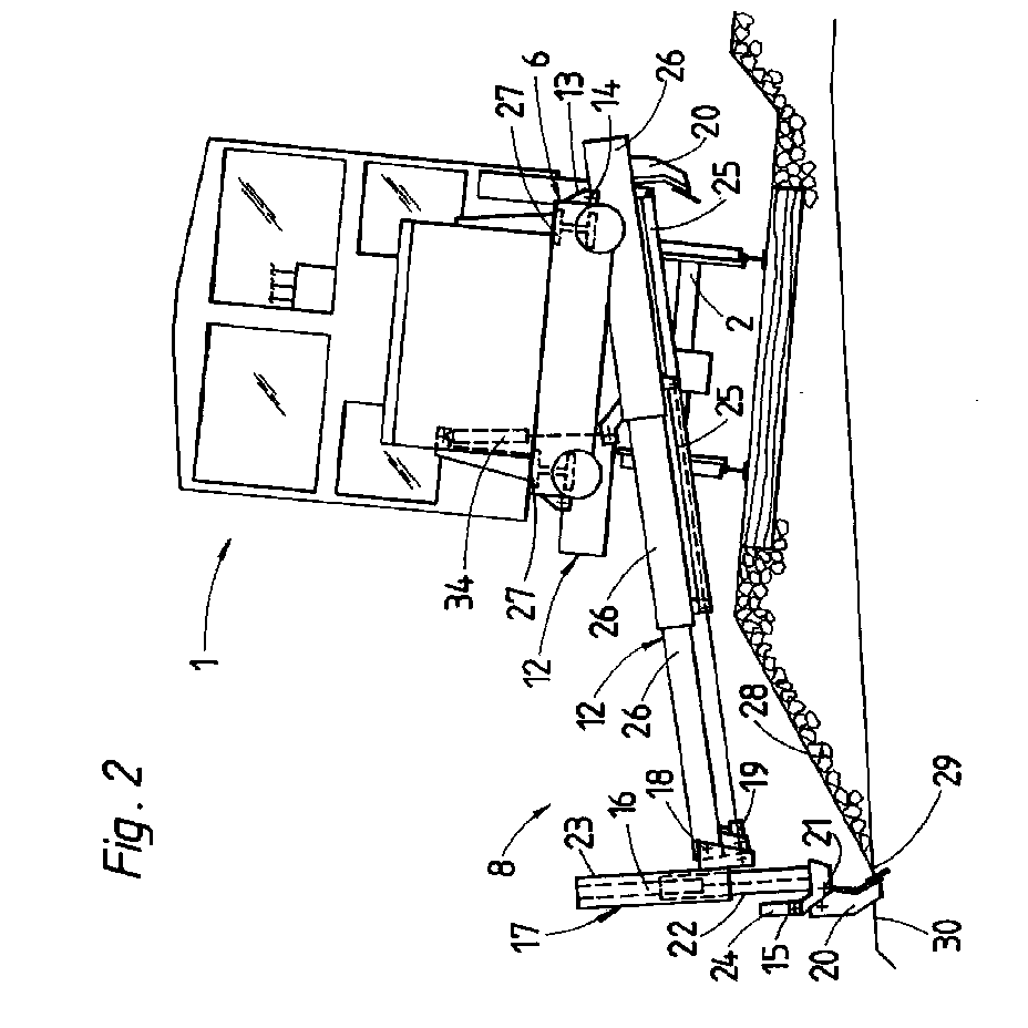
Description
Die Erfindung betrifft einen Schotterpflug mit einem auf Schienenfahrwerken abgestützten Maschinenrahmen, dem ein durch Antriebe höhenverstellbarer Mittelpflug und an jeder Maschinenlängsseite ein höhenverstellbarer, einen mit Schotter in Kontakt bringbaren Pflugschild aufweisender Flankenpflug mit einer Anlenkstelle und einem teleskopförmig verlängerbaren, senkrecht zur Maschinenlängsrichtung verlaufenden Tragrahmen zugeordnet ist.The invention relates to a ballast plow with a machine frame supported on rail bogies, to which a center plow that is height-adjustable by drives and a height-adjustable side plow that has a plow blade that can be brought into contact with ballast and has a linkage point and a telescopically extendable support frame that extends perpendicular to the machine longitudinal direction is assigned to each side of the machine.
Durch die US 5,097,608 B ist ein Schotterpflug mit einem auf Schienenfahrwerken abgestützten Maschinenrahmen bekannt. Dieser weist zwischen den Schienenfahrwerken einen höhenverstellbaren Mittelpflug und diesem vorgeordnete Flankenpflüge auf. Jeder Flankenpflug ist durch eine seitliche am Maschinenrahmen angeordnete, eine in Maschinenlängsrichtung verlaufende Achse aufweisende Anlenkstelle mit dem Maschinenrahmen verbunden und weist einen durch einen Antrieb teleskopförmig in Maschinenquerrichtung verlängerbaren Tragrahmen auf.From US 5,097,608 B a ballast plow with a machine frame supported on rail bogies is known. This has a height-adjustable middle plow between the rail carriages and this upstream side plows. Each side plow is connected to the machine frame by a articulation point arranged on the side of the machine frame and having an axis running in the longitudinal direction of the machine, and has a support frame that can be extended telescopically in the cross-machine direction by a drive.
Die Aufgabe der vorliegenden Erfindung liegt nun in der Schaffung eines Schotterpfluges der eingangs beschriebenen Art, dessen Flankenpflüge auch zur Bearbeitung des an den Kronenfuß der Schotterbettung anschließenden Randwegbereiches einsetzbar sind.The object of the present invention is now to create a ballast plow of the type described in the introduction, the side plows of which can also be used for machining the edge path area adjoining the crown foot of the ballast bed.
Diese Aufgabe wird mit einem Schotterpflug der eingangs beschriebenen Art dadurch gelöst, daß die Anlenkstelle - in Maschinenquerrichtung gesehen - jeweils auf der vom zugeordneten Pflugschild des Flankenpfluges weiter entfernten Maschinenlängsseite angeordnet ist und der Pflugschild um eine in Maschinenlängsrichtung verlaufende Achse verschwenkbar gelagert und mit einem Flankenwinkel-Einstellantrieb verbunden ist.This object is achieved with a ballast plow of the type described at the outset in that the articulation point - viewed in the machine transverse direction - is arranged on the longitudinal side of the machine which is farther from the associated plow shield of the side plow and the plow shield is mounted so as to be pivotable about an axis running in the machine longitudinal direction and with a side angle Adjusting drive is connected.
Durch diese Merkmalskombination ist sowohl eine Verlängerung des Tragrahmens und damit des Arbeitsbereiches als auch eine rasche Änderung des Flankenwinkels erzielbar, sodaß zusätzlich zur Bettungsflanke auch der in den meisten Fällen eine horizontale Fläche bildende Randwegbereich problemlos bearbeitbar ist. Die spezielle Anlenkung des Tragrahmens am Maschinenrahmen gewährleistet außerdem noch eine für die Überstellfahrt sehr vorteilhafte Anordnung des Tragrahmens unterhalb des Maschinenrahmens. Dies beeinflußt weder die Sicht von der Fahrkabine auf das Gleis noch liegt eine nachteilige Beeinträchtigung für den Fall vor, daß unter Einsatz lediglich des Mittelpfluges die beiden Flankenpflüge sich in einer Außerbetriebstellung befinden.With this combination of features, both an extension of the support frame and thus the working area as well as a rapid change in the flank angle can be achieved, so that in addition to the bedding flank, the edge path area, which in most cases forms a horizontal surface, can be processed without problems. The special articulation of the support frame on the machine frame also ensures an arrangement of the support frame below the machine frame which is very advantageous for the transfer run. This does not affect the view from the cab on the track there is still an adverse impairment in the event that, using only the center plow, the two side plows are in an inoperative position.
Die zweifache schwenkbare Lagerung des Pflugschildes gemäß einer Weiterbildung nach Anspruch 2 oder 3 ermöglicht einen relativ großen Schwenkwinkel, sodaß auch die Bearbeitung eines der Außenschiene eines Überhöhungsabschnittes benachbarten Randweges uneingeschränkt möglich ist.The double pivotable mounting of the plow blade according to a development according to
Die Weiterbildung nach den Ansprüchen 4 bis 6 ermöglicht eine besonders vorteilhafte Konstruktion des Tragrahmens für einen möglichst weiten Verstellbereich des Flankenpfluges, wobei jedoch für die Überstellung des Schotterpfluges das Lichtraumprofil nicht überschritten wird.The development according to
Im folgenden wird die Erfindung anhand eines Ausführungsbeispieles näher beschrieben.The invention is described in more detail below using an exemplary embodiment.
Es zeigen:
- Fig. 1 eine schematisch vereinfachte Seitenansicht eines Schotterpfluges mit einem Mittel- und zwei Flankenpflügen,
- Fig. 2 eine Ansicht der Maschine in Maschinenlängsrichtung, wobei ein Flankenpflug zur Bearbeitung eines Randweges ausgefahren ist, und
- Fig. 3 eine teilweise schematisch dargestellte Draufsicht auf den Flankenpflug gemäß Fig. 2.
- 1 is a schematically simplified side view of a ballast plow with a central and two flank plows,
- Fig. 2 is a view of the machine in the longitudinal direction of the machine, with a side plow extended for processing an edge path, and
- FIG. 3 shows a top view of the side plow according to FIG. 2, shown partially schematically.
Der in Fig. 1 ersichtliche Schotterpflug 1 ist über Schienenfahrwerke 2 auf einem aus Schwellen und Schienen gebildeten Gleis 3 mit Hilfe eines Fahrantriebes 4 verfahrbar. Zwischen den beiden Schienenfahrwerken 2 ist ein Mittelpflug 5 höhenverstellbar mit einem Maschinenrahmen 6 verbunden. In einem nach oben gekröpft ausgebildeten Abschnitt des Maschinenrahmens 6 befindet sich eine höhenverstellbare Kehreinrichtung 7 mit einem Querförderband zum Abtransport von überschüssigem Schotter. Im der Kehreinrichtung 7 gegenüberliegenden Endbereich des Maschinenrahmens 6 sind zwei Flankenpflüge 8 angeordnet, die im folgenden zu den Fig. 2 und 3 noch näher beschrieben werden. Auf dem Maschinenrahmen 6 befindet sich eine Fahrkabine 9 mit einer zentralen Steuereinrichtung 10 sowie eine Energiezentrale 11.The ballast plow 1 shown in FIG. 1 can be moved via
Der in Fig. 2 und 3 ersichtliche Flankenpflug 8 ist auf einem senkrecht zur Maschinenlängsrichtung verlaufenden, teleskopförmig ausgebildeten Tragrahmen 12 befestigt. Dieser ist wiederum unter Bildung einer Anlenkstelle 13 um eine in Maschinenlängsrichtung verlaufende Achse 14 verschwenkbar auf der vom Flankenpflug 8 in Maschinenquerrichtung weiter entfernten Maschinenlängsseite des Maschinenrahmens 6 befestigt.The
Der Pflugschild 20 ist mitsamt einem Flankenwinkel-Einstellantrieb 15 und einem Höhenverstellantrieb 16 auf einem Tragkörper 17 gelagert, der seinerseits um eine in Maschinenlängsrichtung verlaufende Schwenkachse 18 verschwenkbar am teleskopförmigen Tragrahmen 12 gelagert und mit einem Schwenkantrieb 19 verbunden ist. Der in Maschinenlängsrichtung verlaufende Pflugschild 20 des Flankenpfluges 8 ist um eine in Maschinenlängsrichtung verlaufende Achse 21 verschwenkbar am unteren Ende eines inneren Teleskoprohres 22 des Tragkörpers 17 befestigt. Dieses ist in dessen Längsrichtung in einem äußeren, um die Schwenkachse 18 verschwenkbar gelagerten Teleskoprohr 23 verschiebbar gelagert. Zur Verstellung des Pflugschildes 20 um die genannte Achse 21 ist ein Flankenwinkel-Einstellzylinder 24 vorgesehen.The
Für die - bezüglich der Maschinenlängsrichtung - Querverstellung des Tragrahmens 12 sind zwei Antriebe 25 vorgesehen. Der Tragrahmen 12 setzt sich aus drei ineinander querverschiebbaren Teilen 26 zusammen, wobei der vom Pflugschild 20 am weitesten entfernte Teil 26 sowohl mit der Anlenkstelle 13 als auch mit einem Antrieb 34 für die Höhenverstellung verbunden ist. Dieser Antrieb 34 ist zwischen zwei in Maschinenquerrichtung voneinander distanzierten Längsträgern 27 des Maschinenrahmens 6 auf dem von der Anlenkstelle 13 weiter entfernten Längsträger 27 befestigt.Two
In der in Fig. 2 dargestellten Arbeitsstellung befindet sich der Pflugschild 20 bereits auf einem an einem Kronenfuß 29 einer Schotterbettflanke 28 anschließenden Randwegbereich 30 (Die Zubringer-Pflugschilder sind der besseren Übersicht wegen in Fig. 2 nicht dargestellt). Die Distanz zwischen der Anlenkstelle 13 des Tragrahmens 12 und dem pflugseitigen, mit dem Antrieb 34 verbundenen Ende des Tragrahmen-Teiles 26 ist kleiner als die bzw. gleich der Distanz der beiden Längsträger 27 zueinander.In the working position shown in FIG. 2, the
In Maschinenlängsrichtung gesehen befindet sich unmittelbar hinter dem im Arbeitseinsatz dargestellten Flankenpflug 8 noch ein weiterer Flankenpflug 8 in einer Überstellposition.Viewed in the longitudinal direction of the machine, a
Wie in Fig. 3 ersichtlich, schließt sowohl an das vordere als auch hintere Ende des Pflugschildes 20 jeweils ein Zubringer-Pflugschild 31 an. Diese sind jeweils durch einen Antrieb 32 um eine senkrecht zur unteren Kante des Pflugschildes 20 verlaufende Achse 33 verschwenkbar ausgebildet. Durch entsprechende Abwinkelung dieser Zubringer-Pflugschilde 31 (siehe Darstellung mit vollen bzw. strichpunktierten Linien) besteht die Möglichkeit, den Flankenpflug 8 in beiden Fahrtrichtungen des Schotterpfluges 1 einzusetzen.As can be seen in FIG. 3, a
Claims (6)
Applications Claiming Priority (2)
| Application Number | Priority Date | Filing Date | Title |
|---|---|---|---|
| AT108492 | 1992-05-25 | ||
| AT1084/92 | 1992-05-25 |
Publications (3)
| Publication Number | Publication Date |
|---|---|
| EP0572370A2 true EP0572370A2 (en) | 1993-12-01 |
| EP0572370A3 EP0572370A3 (en) | 1994-03-30 |
| EP0572370B1 EP0572370B1 (en) | 1996-05-29 |
Family
ID=3506242
Family Applications (1)
| Application Number | Title | Priority Date | Filing Date |
|---|---|---|---|
| EP93890083A Expired - Lifetime EP0572370B1 (en) | 1992-05-25 | 1993-04-21 | Ballast plow |
Country Status (13)
| Country | Link |
|---|---|
| US (1) | US5435081A (en) |
| EP (1) | EP0572370B1 (en) |
| JP (1) | JP3093516B2 (en) |
| CN (1) | CN1030262C (en) |
| AT (1) | ATE138706T1 (en) |
| AU (1) | AU661148B2 (en) |
| CA (1) | CA2093311C (en) |
| CZ (1) | CZ279091B6 (en) |
| DE (1) | DE59302729D1 (en) |
| ES (1) | ES2088658T3 (en) |
| PL (1) | PL171647B1 (en) |
| RU (1) | RU2044810C1 (en) |
| SK (1) | SK279073B6 (en) |
Cited By (4)
| Publication number | Priority date | Publication date | Assignee | Title |
|---|---|---|---|---|
| WO2008089732A3 (en) * | 2007-01-22 | 2008-10-16 | Lima Gmbh & Co Betr S Kg | Method for cleaning, clearing, and/or treating an elongate path |
| EP2213795A3 (en) * | 2009-02-03 | 2013-01-09 | Ralf Zürcher | Device for carrying out work outside the vicinity of tracks of rail sections |
| WO2020191420A1 (en) | 2019-03-27 | 2020-10-01 | Stmg-Gmbh | Ballast levelling machine |
| EP3943663A1 (en) | 2020-07-22 | 2022-01-26 | System 7 Ballast Regulator GmbH | Bulkhead levelling machine |
Families Citing this family (13)
| Publication number | Priority date | Publication date | Assignee | Title |
|---|---|---|---|---|
| US5701693A (en) * | 1996-01-22 | 1997-12-30 | Edge Development, Inc. | Berm clearing attachment for road clearing vehicles |
| US6382329B2 (en) * | 1999-05-04 | 2002-05-07 | John G. Pitts | Ballast plow |
| AT3879U3 (en) * | 2000-06-09 | 2001-03-26 | Plasser Bahnbaumasch Franz | MACHINE FOR RENEWING A TRACK |
| AT4241U3 (en) * | 2001-01-29 | 2001-11-26 | Plasser Bahnbaumasch Franz | MACHINE WITH A BULLET DEVICE AND METHOD |
| US20080313933A1 (en) * | 2007-06-19 | 2008-12-25 | James Dwain Cooper | Backfill attachment device |
| DE102009007224A1 (en) * | 2009-02-03 | 2010-08-05 | Zürcher, Ralf | Method for laying U-shaped channel elements next to the track of a railway line |
| DE102009007222B4 (en) * | 2009-02-03 | 2015-02-12 | Ralf Zürcher | Track vehicle for excavating a trench parallel to a track on railway lines |
| DE102009007226B4 (en) * | 2009-02-03 | 2012-11-22 | Ralf Zürcher | Method for creating a drainage device next to the track of a railway line |
| JP6062302B2 (en) * | 2013-03-28 | 2017-01-18 | サトーホールディングス株式会社 | Bicycle parking ticket, temporary storage system using the same, and temporary storage method |
| CN104060506B (en) * | 2014-06-30 | 2017-01-04 | 中国铁建高新装备股份有限公司 | A kind of railway roadbed side slope shaping methods and device |
| US9428866B2 (en) | 2014-09-23 | 2016-08-30 | Nordco Inc. | Segmented railway regulator blade |
| CN108265574B (en) * | 2018-02-09 | 2024-05-03 | 湖北时瑞达重型工程机械有限公司 | Side plow device of ballasting and shaping vehicle |
| CN109667202B (en) * | 2019-01-25 | 2024-03-08 | 泉州市劲力工程机械有限公司 | A kind of ballast removing machine |
Family Cites Families (13)
| Publication number | Priority date | Publication date | Assignee | Title |
|---|---|---|---|---|
| US971460A (en) * | 1910-04-05 | 1910-09-27 | Rasmus J Meland | Marking and trimming device. |
| US1167900A (en) * | 1915-01-22 | 1916-01-11 | Jorgen Jacobsen | Ballast-trimmer. |
| US3019536A (en) * | 1957-07-19 | 1962-02-06 | Kershaw Mfg Company Inc | Railway ballast equipment |
| DE1952715B1 (en) * | 1969-10-20 | 1971-05-06 | Windhoff Rheiner Maschf | Machine movable on the track for ballasting the track |
| CH600043A5 (en) * | 1977-06-16 | 1978-06-15 | Matisa Materiel Ind Sa | |
| CA1157318A (en) * | 1979-02-22 | 1983-11-22 | Loram Maintenance Of Way, Inc. | Method and apparatus for removing railway ties |
| US4464995A (en) * | 1979-02-22 | 1984-08-14 | Loram Maintenance Of Way, Inc. | Method and apparatus for removing railway ties |
| US4266352A (en) * | 1979-10-11 | 1981-05-12 | Canron Corporation | Ballast side plow |
| IT1181182B (en) * | 1984-06-07 | 1987-09-23 | Danieli Off Mecc | PROFILING GROUP FOR TRANSFERING MACHINES FOR MASS |
| EP0164163B1 (en) * | 1984-06-07 | 1989-02-08 | DANIELI & C. OFFICINE MECCANICHE S.p.A. | Self-propelled machine to dress and re-distribute railway road bed ballast |
| ES2032604T3 (en) * | 1988-08-31 | 1993-02-16 | Franz Plasser Bahnbaumaschinen- Industriegesellschaft M.B.H. | MOBILE MACHINE ON RAILS FOR DISTRIBUTOR AND PROFILING THE BALLAST BED OF A VIA. |
| US4951573A (en) * | 1988-09-06 | 1990-08-28 | Harsco Corporation | Tie remover and inserter |
| AT398213B (en) * | 1989-10-31 | 1994-10-25 | Plasser Bahnbaumasch Franz | MACHINE FOR RECEIVING AND DISTRIBUTING THE BEDGING BALL |
-
1993
- 1993-04-02 CA CA002093311A patent/CA2093311C/en not_active Expired - Fee Related
- 1993-04-21 AT AT93890083T patent/ATE138706T1/en not_active IP Right Cessation
- 1993-04-21 ES ES93890083T patent/ES2088658T3/en not_active Expired - Lifetime
- 1993-04-21 DE DE59302729T patent/DE59302729D1/en not_active Expired - Fee Related
- 1993-04-21 EP EP93890083A patent/EP0572370B1/en not_active Expired - Lifetime
- 1993-05-17 CZ CZ93914A patent/CZ279091B6/en not_active IP Right Cessation
- 1993-05-18 US US08/063,454 patent/US5435081A/en not_active Expired - Fee Related
- 1993-05-19 SK SK503-93A patent/SK279073B6/en unknown
- 1993-05-20 PL PL93299012A patent/PL171647B1/en not_active IP Right Cessation
- 1993-05-24 AU AU38755/93A patent/AU661148B2/en not_active Ceased
- 1993-05-24 CN CN93106455A patent/CN1030262C/en not_active Expired - Fee Related
- 1993-05-24 JP JP05121236A patent/JP3093516B2/en not_active Expired - Fee Related
- 1993-05-24 RU RU9393005083A patent/RU2044810C1/en not_active IP Right Cessation
Cited By (4)
| Publication number | Priority date | Publication date | Assignee | Title |
|---|---|---|---|---|
| WO2008089732A3 (en) * | 2007-01-22 | 2008-10-16 | Lima Gmbh & Co Betr S Kg | Method for cleaning, clearing, and/or treating an elongate path |
| EP2213795A3 (en) * | 2009-02-03 | 2013-01-09 | Ralf Zürcher | Device for carrying out work outside the vicinity of tracks of rail sections |
| WO2020191420A1 (en) | 2019-03-27 | 2020-10-01 | Stmg-Gmbh | Ballast levelling machine |
| EP3943663A1 (en) | 2020-07-22 | 2022-01-26 | System 7 Ballast Regulator GmbH | Bulkhead levelling machine |
Also Published As
| Publication number | Publication date |
|---|---|
| CZ279091B6 (en) | 1994-12-15 |
| JPH0633401A (en) | 1994-02-08 |
| JP3093516B2 (en) | 2000-10-03 |
| AU661148B2 (en) | 1995-07-13 |
| RU2044810C1 (en) | 1995-09-27 |
| SK50393A3 (en) | 1993-12-08 |
| PL171647B1 (en) | 1997-05-30 |
| US5435081A (en) | 1995-07-25 |
| CZ91493A3 (en) | 1993-12-15 |
| EP0572370B1 (en) | 1996-05-29 |
| PL299012A1 (en) | 1994-01-10 |
| AU3875593A (en) | 1993-12-02 |
| SK279073B6 (en) | 1998-06-03 |
| EP0572370A3 (en) | 1994-03-30 |
| ATE138706T1 (en) | 1996-06-15 |
| DE59302729D1 (en) | 1996-07-04 |
| CA2093311C (en) | 2003-12-16 |
| CA2093311A1 (en) | 1993-11-26 |
| CN1030262C (en) | 1995-11-15 |
| CN1079791A (en) | 1993-12-22 |
| ES2088658T3 (en) | 1996-08-16 |
Similar Documents
| Publication | Publication Date | Title |
|---|---|---|
| EP0572370B1 (en) | Ballast plow | |
| AT400337B (en) | TRACKING MACHINE WITH STAMPING UNITS ADJUSTABLE IN THE TRACK DIRECTION | |
| DD292492A5 (en) | RUNNING RUNNING, LEVELING AND DIRECTION MACHINE | |
| AT506585B1 (en) | tamping machine | |
| AT402952B (en) | TRACK CONSTRUCTION MACHINE FOR CONTROLLED LOWERING OF A TRACK | |
| DE2709435C3 (en) | Screed | |
| DE1658339C3 (en) | Track tamping and straightening machine | |
| DE2926045C2 (en) | Track construction machine for distributing and profiling the ballast of a track | |
| EP0416135B1 (en) | Track-mobile machine for distributing and profiling the bedding ballast of a railway track | |
| DE2649797C2 (en) | Track maintenance machine for leveling and straightening switches and crossings | |
| DD153404A5 (en) | Tamping machine | |
| DE2945482A1 (en) | TRACK CONSTRUCTION MACHINE WITH A GRAVEL PLOW ARRANGEMENT | |
| DE19511539B4 (en) | Work car with a working platform | |
| DD293853A5 (en) | RUNNING DRIPPING MACHINE | |
| DE2615629B2 (en) | Shield support frame | |
| DE19645615C2 (en) | Single or double-sided vine leaf cutter | |
| EP0428781A1 (en) | Track maintenance machine for distributing and profiling the track bedding ballast | |
| DE2851947C2 (en) | Track construction machine for distributing and profiling the ballast of a track | |
| DE29509349U1 (en) | Combined rail road vehicle with a working platform | |
| DE2745446C2 (en) | Device for level control of a mining machine, in particular a planer | |
| AT392498B (en) | MOBILE TRACKING MACHINE WITH CROSS- AND HEIGHT-ADJUSTABLE STOPPING UNITS | |
| DE2911604C2 (en) | Space loader with assigned tripper car | |
| DD200031A5 (en) | DEVICE FOR SETTING UP RIDING BEDS | |
| DE69200309T2 (en) | Plow with a device for regulating the inclination and the side grip. | |
| EP0270096A1 (en) | Snow track vehicle with a tool carrier |
Legal Events
| Date | Code | Title | Description |
|---|---|---|---|
| PUAI | Public reference made under article 153(3) epc to a published international application that has entered the european phase |
Free format text: ORIGINAL CODE: 0009012 |
|
| AK | Designated contracting states |
Kind code of ref document: A2 Designated state(s): AT CH DE ES FR GB IT LI NL |
|
| 17P | Request for examination filed |
Effective date: 19931210 |
|
| PUAL | Search report despatched |
Free format text: ORIGINAL CODE: 0009013 |
|
| AK | Designated contracting states |
Kind code of ref document: A3 Designated state(s): AT CH DE ES FR GB IT LI NL |
|
| 17Q | First examination report despatched |
Effective date: 19951109 |
|
| GRAH | Despatch of communication of intention to grant a patent |
Free format text: ORIGINAL CODE: EPIDOS IGRA |
|
| GRAA | (expected) grant |
Free format text: ORIGINAL CODE: 0009210 |
|
| AK | Designated contracting states |
Kind code of ref document: B1 Designated state(s): AT CH DE ES FR GB IT LI NL |
|
| REF | Corresponds to: |
Ref document number: 138706 Country of ref document: AT Date of ref document: 19960615 Kind code of ref document: T |
|
| REG | Reference to a national code |
Ref country code: CH Ref legal event code: NV Representative=s name: DIPL.-ING. ETH H. R. WERFFELI PATENTANWALT |
|
| ITF | It: translation for a ep patent filed | ||
| REF | Corresponds to: |
Ref document number: 59302729 Country of ref document: DE Date of ref document: 19960704 |
|
| REG | Reference to a national code |
Ref country code: ES Ref legal event code: BA2A Ref document number: 2088658 Country of ref document: ES Kind code of ref document: T3 |
|
| GBT | Gb: translation of ep patent filed (gb section 77(6)(a)/1977) |
Effective date: 19960625 |
|
| REG | Reference to a national code |
Ref country code: ES Ref legal event code: FG2A Ref document number: 2088658 Country of ref document: ES Kind code of ref document: T3 |
|
| ET | Fr: translation filed | ||
| PLBE | No opposition filed within time limit |
Free format text: ORIGINAL CODE: 0009261 |
|
| STAA | Information on the status of an ep patent application or granted ep patent |
Free format text: STATUS: NO OPPOSITION FILED WITHIN TIME LIMIT |
|
| 26N | No opposition filed | ||
| REG | Reference to a national code |
Ref country code: GB Ref legal event code: IF02 |
|
| PGFP | Annual fee paid to national office [announced via postgrant information from national office to epo] |
Ref country code: GB Payment date: 20050225 Year of fee payment: 13 |
|
| PGFP | Annual fee paid to national office [announced via postgrant information from national office to epo] |
Ref country code: AT Payment date: 20050304 Year of fee payment: 13 |
|
| PGFP | Annual fee paid to national office [announced via postgrant information from national office to epo] |
Ref country code: FR Payment date: 20050324 Year of fee payment: 13 |
|
| PGFP | Annual fee paid to national office [announced via postgrant information from national office to epo] |
Ref country code: CH Payment date: 20050325 Year of fee payment: 13 |
|
| PGFP | Annual fee paid to national office [announced via postgrant information from national office to epo] |
Ref country code: NL Payment date: 20050331 Year of fee payment: 13 |
|
| PGFP | Annual fee paid to national office [announced via postgrant information from national office to epo] |
Ref country code: ES Payment date: 20050421 Year of fee payment: 13 |
|
| PGFP | Annual fee paid to national office [announced via postgrant information from national office to epo] |
Ref country code: DE Payment date: 20050627 Year of fee payment: 13 |
|
| PG25 | Lapsed in a contracting state [announced via postgrant information from national office to epo] |
Ref country code: GB Free format text: LAPSE BECAUSE OF NON-PAYMENT OF DUE FEES Effective date: 20060421 Ref country code: AT Free format text: LAPSE BECAUSE OF NON-PAYMENT OF DUE FEES Effective date: 20060421 |
|
| PG25 | Lapsed in a contracting state [announced via postgrant information from national office to epo] |
Ref country code: ES Free format text: LAPSE BECAUSE OF NON-PAYMENT OF DUE FEES Effective date: 20060422 |
|
| PG25 | Lapsed in a contracting state [announced via postgrant information from national office to epo] |
Ref country code: LI Free format text: LAPSE BECAUSE OF NON-PAYMENT OF DUE FEES Effective date: 20060430 Ref country code: CH Free format text: LAPSE BECAUSE OF NON-PAYMENT OF DUE FEES Effective date: 20060430 |
|
| PGFP | Annual fee paid to national office [announced via postgrant information from national office to epo] |
Ref country code: IT Payment date: 20060430 Year of fee payment: 14 |
|
| PG25 | Lapsed in a contracting state [announced via postgrant information from national office to epo] |
Ref country code: NL Free format text: LAPSE BECAUSE OF NON-PAYMENT OF DUE FEES Effective date: 20061101 Ref country code: DE Free format text: LAPSE BECAUSE OF NON-PAYMENT OF DUE FEES Effective date: 20061101 |
|
| REG | Reference to a national code |
Ref country code: CH Ref legal event code: PL |
|
| GBPC | Gb: european patent ceased through non-payment of renewal fee |
Effective date: 20060421 |
|
| NLV4 | Nl: lapsed or anulled due to non-payment of the annual fee |
Effective date: 20061101 |
|
| REG | Reference to a national code |
Ref country code: FR Ref legal event code: ST Effective date: 20061230 |
|
| REG | Reference to a national code |
Ref country code: ES Ref legal event code: FD2A Effective date: 20060422 |
|
| PG25 | Lapsed in a contracting state [announced via postgrant information from national office to epo] |
Ref country code: FR Free format text: LAPSE BECAUSE OF NON-PAYMENT OF DUE FEES Effective date: 20060502 |
|
| PG25 | Lapsed in a contracting state [announced via postgrant information from national office to epo] |
Ref country code: IT Free format text: LAPSE BECAUSE OF NON-PAYMENT OF DUE FEES Effective date: 20070421 |