EP0572357A2 - Wardrobe-type unit with coaxially hinged, double-leaved doors fitted with mirrors on the sides facing each other when the doors are closed - Google Patents
Wardrobe-type unit with coaxially hinged, double-leaved doors fitted with mirrors on the sides facing each other when the doors are closed Download PDFInfo
- Publication number
- EP0572357A2 EP0572357A2 EP19930830155 EP93830155A EP0572357A2 EP 0572357 A2 EP0572357 A2 EP 0572357A2 EP 19930830155 EP19930830155 EP 19930830155 EP 93830155 A EP93830155 A EP 93830155A EP 0572357 A2 EP0572357 A2 EP 0572357A2
- Authority
- EP
- European Patent Office
- Prior art keywords
- panels
- doors
- fitted
- mirrors
- wardrobe
- Prior art date
- Legal status (The legal status is an assumption and is not a legal conclusion. Google has not performed a legal analysis and makes no representation as to the accuracy of the status listed.)
- Withdrawn
Links
- 238000002955 isolation Methods 0.000 description 3
- 230000000007 visual effect Effects 0.000 description 1
Images

Classifications
-
- A—HUMAN NECESSITIES
- A47—FURNITURE; DOMESTIC ARTICLES OR APPLIANCES; COFFEE MILLS; SPICE MILLS; SUCTION CLEANERS IN GENERAL
- A47B—TABLES; DESKS; OFFICE FURNITURE; CABINETS; DRAWERS; GENERAL DETAILS OF FURNITURE
- A47B61/00—Wardrobes
Definitions
- the subject of the invention is a wardrobe-type unit offering the option of a very large mirrored surface having several parts which can be orientated in various ways to enhance the visual effect and make it more functional.
- the wardrobe-type unit in question has a leaved door formed by two coaxially hinged panels with the two facing sides fitted with mirrors; said two panels can be moved angularly remaining joined together or they can be moved independently so as to open the outer panel, thereby exposing the two sides fitted with mirrors, one of which can be orientated, which remain adjacent to each other.
- the wardrobe-type unit has two leaved doors, each door being formed by two panels with mirrors on the two facing sides, the outer panel of which can be opened even independently of the inner panel.
- This arrangement gives up to four mirrored sides, the outer two of which can be orientated.
- a bolt means can be provided on the or on each outer panel in order to lock onto or release the inner panel, thereby moving the two panels together as one or moving only the outer panel.
- the or each inner panel can be fitted with a catch or bolt or better still with force-operated means such as a magnetic means, a mechanical pressure means, or other equivalent means.
- the two panels of the or each leave can be fitted using hinges having three attachment points, one for the wardrobe frame, one for the outer panel and one for the inner panel; the last can be connected to the hinge via a small intermediate shaped block.
- the reference numeral 1 indicates the frame or carcass of the piece of furniture, the inside 3 of which can be accessed by opening a pair of doors or leaves which are symmetrical about a vertical plane.
- a smaller piece of furniture could have a single leaf instead of two symmetrical leaves.
- each door i.e. each leaf consists of two panels, i.e. an outer panel 5 and an inner panel 7; the two panels 5 and 7 are coaxially hinged together whereby they can be moved angularly in order to obtain the closed and the open positions either independently of each other or simultaneously.
- the two panels are side by side, they are very close together and have two facing surfaces, as can be seen in Fig.
- Independent closing and opening means may be provided on the inner panels and on the outer panels, or alternatively means connecting the inner leaf to the outer leaf may also be provided; it is therefore possible either to open the outer panel and the inner panel independently one after the other, or to open the two adjacent panels simultaneously in order to obtain the arrangement shown in Fig. 1; the same applies to closing the panels.
- the reference 1A indicates an upright which forms part of the carcass 1 and which is vertically adjacent to the access openings which are closed by the pairs of panels.
- the reference 10 indicates a hinge which extends vertically and has at least one triple attachment point or better still at least two triple attachment points, specifically: an attachment point 10A for the upright 1A (see Fig. 3); an attachment point 10B for the outer panel 5 (see Fig. 4); and an attachment point 10C for the inner panel 7.
- 10A and 10B are attached directly to the upright 1A and the panel 5 respectively, whereas 10C is attached to the inner panel 7 by means of the interposition of a small block 12 (see Fig. 5); the block 12 is comprehensively shown in Figs. 10, 11 and 12 in isolation. Said block 12 fits in a recess 1B in the upright 1A.
- the outer panels 5 can be coupled together in various ways, for example in a tongue-and-grooved manner as shown at 14 in Fig. 9.
- the inner panels can be kept in the closed position by means of a mechanical spring latch or magnetic type system which, to a limited extent, keeps them fastened to the frame 1.
- Each outer panel 5 can be provided with a vertical sliding bolt as indicated at 16 in Fig. 9, which can engage with a mouth 18 fixed via a bracket element 20 which is firmly attached to the top edge or to the bottom edge of the corresponding inner panel 7. Therefore, by keeping the bolt 16, 18 locked, when the outer panels 5 are opened using the handles or knobs this also causes the corresponding inner panels 7 to be opened at the same time; by unlocking the bolt 16, 18, when the outer panel is opened it does not also carry with it the corresponding inner panel 7, which remains fastened to the carcass of the piece of furniture by the spring lock or magnetic or other equivalent means.
Landscapes
- Mirrors, Picture Frames, Photograph Stands, And Related Fastening Devices (AREA)
Abstract
The wardrobe-type unit has coaxially hinged, double-leaved doors (5, 7), the two facing sides being fitted with mirrors (S1, S2); the two panels can be moved as one, remaining joined together, or they can be moved independently so as to open only the outer panel (5), thereby exposing the two sides fitted with mirrors which remain adjacent to each other.
Description
- The subject of the invention is a wardrobe-type unit offering the option of a very large mirrored surface having several parts which can be orientated in various ways to enhance the visual effect and make it more functional.
- These and other aims and advantages will emerge from the following text.
- Basically, the wardrobe-type unit in question has a leaved door formed by two coaxially hinged panels with the two facing sides fitted with mirrors; said two panels can be moved angularly remaining joined together or they can be moved independently so as to open the outer panel, thereby exposing the two sides fitted with mirrors, one of which can be orientated, which remain adjacent to each other.
- In practice, the wardrobe-type unit has two leaved doors, each door being formed by two panels with mirrors on the two facing sides, the outer panel of which can be opened even independently of the inner panel. This arrangement gives up to four mirrored sides, the outer two of which can be orientated.
- A bolt means can be provided on the or on each outer panel in order to lock onto or release the inner panel, thereby moving the two panels together as one or moving only the outer panel. The or each inner panel can be fitted with a catch or bolt or better still with force-operated means such as a magnetic means, a mechanical pressure means, or other equivalent means.
- The two panels of the or each leave can be fitted using hinges having three attachment points, one for the wardrobe frame, one for the outer panel and one for the inner panel; the last can be connected to the hinge via a small intermediate shaped block.
- The drawing shows one possible embodiment of the invention, and specifically:
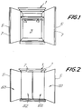
- Figs. 1 and 2 show perspective front views of a wardrobe with its doors open allowing access to the inside, and with only the outer panels open to form a quadruple mirrored surface, respectively;
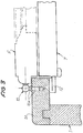
- Figs. 3, 4 and 5 show local horizontal cross-sections illustrating the hinged articulations between the frame of the piece of furniture, the outer panel and the inner panel;
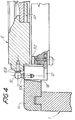
- Figs. 6, 7 and 8 show, in isolation, the area where the hinge is attached to the inner panel, respectively in isolation as viewed in Fig. 5 and through VII-VII and VIII-VIII as marked in Fig. 6;
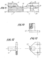
- Fig. 9 shows a detail of where the two double doors are coupled together when closed;
- Figs. 10, 11 and 12 show a small intermediate block used to hinge the inner panel of one door;
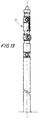
- Fig. 13 shows a partial view of a hinge which may be fitted according to the model.
- Following the illustrations for the attached drawing and with initial reference to Figs. 1 and 2, the
reference numeral 1 indicates the frame or carcass of the piece of furniture, the inside 3 of which can be accessed by opening a pair of doors or leaves which are symmetrical about a vertical plane. A smaller piece of furniture could have a single leaf instead of two symmetrical leaves. - The invention is characterised in that each door i.e. each leaf consists of two panels, i.e. an
outer panel 5 and aninner panel 7; the twopanels leaves 7 are kept closed and theouter panels 5 are opened, this gives four mirrored areas S1, S2, S2, S1 respectively; the two mirrored areas S2 face forwards in the same plane, whereas the two outer mirrored areas S1 can be oriented in various ways and independently of each other, either symmetrically or asymmetrically, thereby giving particular reflections so that the person using the mirror can look at him or herself from the back as well as from the front. - Independent closing and opening means may be provided on the inner panels and on the outer panels, or alternatively means connecting the inner leaf to the outer leaf may also be provided; it is therefore possible either to open the outer panel and the inner panel independently one after the other, or to open the two adjacent panels simultaneously in order to obtain the arrangement shown in Fig. 1; the same applies to closing the panels.
- Figs 4 to the end shows certain specific solutions for the concept set forth above. The
reference 1A indicates an upright which forms part of thecarcass 1 and which is vertically adjacent to the access openings which are closed by the pairs of panels. Thereference 10 indicates a hinge which extends vertically and has at least one triple attachment point or better still at least two triple attachment points, specifically: an attachment point 10A for the upright 1A (see Fig. 3); anattachment point 10B for the outer panel 5 (see Fig. 4); and anattachment point 10C for theinner panel 7. 10A and 10B are attached directly to the upright 1A and thepanel 5 respectively, whereas 10C is attached to theinner panel 7 by means of the interposition of a small block 12 (see Fig. 5); theblock 12 is comprehensively shown in Figs. 10, 11 and 12 in isolation. Said block 12 fits in arecess 1B in the upright 1A. - When the
inner panels 7 are closed they stand centrally side by side so that the mirrored areas S2 are substantially adjoining. Theouter panels 5 can be coupled together in various ways, for example in a tongue-and-grooved manner as shown at 14 in Fig. 9. - The inner panels can be kept in the closed position by means of a mechanical spring latch or magnetic type system which, to a limited extent, keeps them fastened to the
frame 1. Eachouter panel 5 can be provided with a vertical sliding bolt as indicated at 16 in Fig. 9, which can engage with amouth 18 fixed via abracket element 20 which is firmly attached to the top edge or to the bottom edge of the correspondinginner panel 7. Therefore, by keeping thebolt outer panels 5 are opened using the handles or knobs this also causes the correspondinginner panels 7 to be opened at the same time; by unlocking thebolt inner panel 7, which remains fastened to the carcass of the piece of furniture by the spring lock or magnetic or other equivalent means. The possibility of also providing means so that theinner panels 7 can be opened independently after theouter panels 5 have been opened, i.e. to give the arrangement shown in Fig. 1 from that shown in Fig. 2, is not excluded. Opening and closing the leaves via thebolt inner panels 7 are completely free from recesses or spaces for hand-holes for opening theinner panels 7; thus the coplanar surfaces S2 appear as a single large mirror. - By independently and suitably adjusting the orientation of the
panels 5 and therefore of the mirrored surfaces S1 in relation to the fixed position of the mirrored surfaces S2, a person standing in front of the mirror described herein can obtain extremely effective reflections of him or herself.
Claims (7)
- Wardrobe-type unit in which a leaved door is formed by two coaxially hinged panels with the two facing sides fitted with mirrors, said two panels being able to be moved angularly remaining joined together or being able to be moved independently so as to open only the outer panel, thereby exposing the two sides fitted with mirrors which remain adjacent to each other.
- Unit according to Claim 1, with two leaved doors, each door being formed by two panels with mirrors on the two facing sides, the outer panel of which can be opened independently of the inner panel.
- Unit according to Claim 1 or 2, in which a bolt means is provided on the or on each outer panel, in order to lock onto or release the corresponding inner panel, thereby moving the two panels together as one or moving only the outer panel.
- Unit according to Claim 3, in which the or each inner panel is fitted with a force-operated catch means, such as a magnetic means, a mechanical pressure means, or other equivalent means.
- Unit according to the preceding claims, in which the two panels are fitted using hinges having three attachment points, one for the wardrobe frame, one for the outer panel and one for the inner panel, the last being via a small intermediate shaped block.
- For a unit according to the preceding claims, a shaped block (12) to join the inner panel, via the back of its mirror, to the hinge.
- Wardrobe-type unit with coaxially hinged, double-leaved doors fitted with mirrors on the sides facing each other when the doors are closed; the whole as described above and illustrated.
Applications Claiming Priority (2)
| Application Number | Priority Date | Filing Date | Title |
|---|---|---|---|
| ITFI920055U | 1992-04-08 | ||
| IT000055 IT228149Y1 (en) | 1992-04-08 | 1992-04-08 | "CABINET CABINET WITH DOUBLE DOORS HINGED COAXIAL AND EQUIPPED WITH MIRRORS ON THE FACES OPPOSED IN |
Publications (1)
| Publication Number | Publication Date |
|---|---|
| EP0572357A2 true EP0572357A2 (en) | 1993-12-01 |
Family
ID=11349989
Family Applications (1)
| Application Number | Title | Priority Date | Filing Date |
|---|---|---|---|
| EP19930830155 Withdrawn EP0572357A2 (en) | 1992-04-08 | 1993-04-08 | Wardrobe-type unit with coaxially hinged, double-leaved doors fitted with mirrors on the sides facing each other when the doors are closed |
Country Status (2)
| Country | Link |
|---|---|
| EP (1) | EP0572357A2 (en) |
| IT (1) | IT228149Y1 (en) |
Cited By (2)
| Publication number | Priority date | Publication date | Assignee | Title |
|---|---|---|---|---|
| WO2012145565A3 (en) * | 2011-04-19 | 2012-12-27 | Thomson Matt | Securable concrete storage facility |
| CN103622380A (en) * | 2013-12-11 | 2014-03-12 | 杭庆永 | Children wardrobe |
-
1992
- 1992-04-08 IT IT000055 patent/IT228149Y1/en active IP Right Grant
-
1993
- 1993-04-08 EP EP19930830155 patent/EP0572357A2/en not_active Withdrawn
Cited By (3)
| Publication number | Priority date | Publication date | Assignee | Title |
|---|---|---|---|---|
| WO2012145565A3 (en) * | 2011-04-19 | 2012-12-27 | Thomson Matt | Securable concrete storage facility |
| US8640409B2 (en) | 2011-04-19 | 2014-02-04 | Matt Thomson | Secureable concrete storage facility |
| CN103622380A (en) * | 2013-12-11 | 2014-03-12 | 杭庆永 | Children wardrobe |
Also Published As
| Publication number | Publication date |
|---|---|
| ITFI920055V0 (en) | 1992-04-08 |
| ITFI920055U1 (en) | 1993-10-08 |
| IT228149Y1 (en) | 1998-02-05 |
Similar Documents
| Publication | Publication Date | Title |
|---|---|---|
| US3345777A (en) | Supporting bracket for windows | |
| US4389748A (en) | Concealed door hinge | |
| US4461120A (en) | Pass door assembly | |
| US2439664A (en) | Glass-lined metal shelf wall closet | |
| US6099096A (en) | Door assembly for a corner cabinet | |
| US6634727B2 (en) | Closet doors with integrated shelves | |
| US3054118A (en) | Shower doors | |
| US2578096A (en) | Medicine cabinet | |
| GB2207171A (en) | A sliding door fitting | |
| EP0572357A2 (en) | Wardrobe-type unit with coaxially hinged, double-leaved doors fitted with mirrors on the sides facing each other when the doors are closed | |
| US6862778B2 (en) | Self-supporting device to hinge toward opposite sides | |
| US4729615A (en) | Wardrobe or other container with folding doors | |
| US6152547A (en) | Wardrobe door structure | |
| GB2308404B (en) | Improvements relating to the security of doors and windows | |
| JPH07313271A (en) | Writing desk | |
| US4606145A (en) | Shutter-type window panel | |
| US3441976A (en) | Two-way hinge | |
| US460344A (en) | Voting-booth | |
| US4357981A (en) | Panic bar assembly | |
| US5201096A (en) | Hinge | |
| JPH024233Y2 (en) | ||
| JPS6133807Y2 (en) | ||
| JP3518681B2 (en) | Oridoor | |
| JPH078760Y2 (en) | Partition device | |
| JPS5820780Y2 (en) | furniture door device |
Legal Events
| Date | Code | Title | Description |
|---|---|---|---|
| PUAI | Public reference made under article 153(3) epc to a published international application that has entered the european phase |
Free format text: ORIGINAL CODE: 0009012 |
|
| AK | Designated contracting states |
Kind code of ref document: A2 Designated state(s): DE FR |
|
| STAA | Information on the status of an ep patent application or granted ep patent |
Free format text: STATUS: THE APPLICATION IS DEEMED TO BE WITHDRAWN |
|
| 18D | Application deemed to be withdrawn |
Effective date: 19951031 |