US6152547A - Wardrobe door structure - Google Patents
Wardrobe door structure Download PDFInfo
- Publication number
- US6152547A US6152547A US09/375,403 US37540399A US6152547A US 6152547 A US6152547 A US 6152547A US 37540399 A US37540399 A US 37540399A US 6152547 A US6152547 A US 6152547A
- Authority
- US
- United States
- Prior art keywords
- side edge
- horizontal
- wardrobe
- rail
- horizontal bottom
- Prior art date
- Legal status (The legal status is an assumption and is not a legal conclusion. Google has not performed a legal analysis and makes no representation as to the accuracy of the status listed.)
- Expired - Fee Related
Links
Images
Classifications
-
- A—HUMAN NECESSITIES
- A47—FURNITURE; DOMESTIC ARTICLES OR APPLIANCES; COFFEE MILLS; SPICE MILLS; SUCTION CLEANERS IN GENERAL
- A47B—TABLES; DESKS; OFFICE FURNITURE; CABINETS; DRAWERS; GENERAL DETAILS OF FURNITURE
- A47B61/00—Wardrobes
Definitions
- the present invention relates to wardrobes, and more specifically to a wardrobe door structure that can easily be opened/closed by sliding.
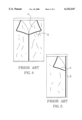
- the collapsible wardrobe covering comprises a double-panel zipper-controlled door structure (see FIG. 4), or a single-panel zipper-controlled door structure (see FIG. 5).
- the door panel A is fastened to the collapsible wardrobe covering by zippers B. When opening the door, the zippers B must be unfastened one after another. When unfastening the vertical zipper, the user may have to sit on the heel. Therefore, it is inconvenient to close/open the door structure at the wardrobe covering.
- the wardrobe door structure comprises a fixed horizontal top rail, a fixed horizontal bottom rail, and a sliding folding door, the sliding folding door having a horizontal top side edge, a horizontal bottom side edge, a first vertical side edge fixedly connected to a wardrobe, a second vertical side edge, a first set of loops arranged along the horizontal top side edge and respectively hung on the horizontal top rail, a second set of loops arranged along the horizontal bottom side edge and respectively hung on the horizontal bottom rail, a vertical rod member fixedly arranged along the second vertical side edge for pulling by hand to move the sliding folding door horizontally along the horizontal top rail and the horizontal bottom rail between the close position and the open position, and a hand hole on the middle adjacent to the vertical rod member through which the hand is inserted to hold the vertical rod member and to pull the vertical rod member in opening/closing the sliding folding door.
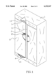
- FIG. 1 is a perspective view of a wardrobe with two sliding folding doors according to the present invention.
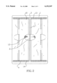
- FIG. 2 is a plain view of the present invention showing the moving direction of the folding sliding doors.
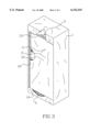
- FIG. 3 is a perspective view of a wardrobe with a single sliding folding door according to the present invention.
- FIG. 4 is a plain view of a wardrobe with a double-panel zipper-controlled door structure according to the prior art.
- FIG. 5 is a plain view of a wardrobe with a single-panel zipper-controlled door structure according to the prior art.
- a wardrobe 1 comprising a fixed transverse top rail 3, a fixed transverse bottom rail 4, two collapsible, rectangular sliding folding doors 10 coupled between the top rail 3 and the bottom rail 4.
- the door folding doors 10 are made of plastic sheet material or soft cloth, each having a horizontal top side edge, a horizontal bottom side edge, a first vertical side edge fixedly connected to the wardrobe 1, a second vertical side edge, a first set of loops 13 and a second set of loops 14 respectively arranged along the horizontal top side edge and the horizontal bottom side edge and hung on the horizontal top rail 3 and the horizontal bottom rail 4, a vertical rod member 2 arranged along the second vertical side edge and fixedly secured thereto by stitches 11, and a hand hole 12 on the middle adjacent to the vertical rod member 2.
- the hand can be inserted through the hand hole 12 at one sliding folding door 10 to hold the respective vertical rod member 2, and then to pull the respective vertical rod member 2 sideways, enabling the sliding folding door 10 to be moved horizontally along the horizontal top rail 3 and the horizontal bottom rail 4 between the close position and the open position.
- FIG. 3 shows an alternate form of the present invention.
- the wardrobe 1 comprises a fixed horizontal top rail 3, a fixed horizontal bottom rail 4, and a sliding folding door 10 moved horizontally along the horizontal top rail 3 and the horizontal bottom rail 4 between the close position and the open position.
- the sliding folding door 10 is made of plastic sheet material or soft cloth, having a horizontal top side edge, a horizontal bottom side edge, a first vertical side edge fixedly connected to the wardrobe 1, a second vertical side edge, a first set of loops 13 and a second set of loops 14 respectively arranged along the horizontal top side edge and the horizontal bottom side edge and hung on the horizontal top rail 3 and the horizontal bottom rail 4, a vertical rod member 2 arranged along the second vertical side edge and secured thereto by stitches 11, and a hand hole 12 on the middle adjacent to the vertical rod member 2.
- the sliding folding door 10 can easily be moved along the horizontal top rail 3 and the horizontal bottom rail 4 to close/open the wardrobe 1.
Abstract
A wardrobe door structure, which includes a fixed horizontal top rail, a fixed horizontal bottom rail, and a sliding folding door, the sliding folding door having a horizontal top side edge, a horizontal bottom side edge, a first vertical side edge fixedly connected to a wardrobe, a second vertical side edge, a first set of loops arranged along the horizontal top side edge and respectively hung on the horizontal top rail, a second set of loops arranged along the horizontal bottom side edge and respectively hung on the horizontal bottom rail, and a vertical rod member fixedly arranged along the second vertical side edge for pulling by hand to move the sliding folding door horizontally along the horizontal top rail and the horizontal bottom rail between the close position and the open position.
Description
The present invention relates to wardrobes, and more specifically to a wardrobe door structure that can easily be opened/closed by sliding.
Regular economic, folding collapsible wardrobes are commonly comprised of a collapsible wardrobe covering, and a folding collapsible frame structure set up in the collapsible covering to support the collapsible wardrobe covering in shape. The collapsible wardrobe covering comprises a double-panel zipper-controlled door structure (see FIG. 4), or a single-panel zipper-controlled door structure (see FIG. 5). The door panel A is fastened to the collapsible wardrobe covering by zippers B. When opening the door, the zippers B must be unfastened one after another. When unfastening the vertical zipper, the user may have to sit on the heel. Therefore, it is inconvenient to close/open the door structure at the wardrobe covering.
It is one object of the present invention to provide a wardrobe door structure for a wardrobe, which can conveniently and quickly opened/closed by sliding. It is another object of the present invention to provide a wardrobe door structure, which can be made in the form of a double sliding door type door structure, or a single sliding door type door structure. According to one embodiment of the present invention, the wardrobe door structure comprises a fixed horizontal top rail, a fixed horizontal bottom rail, and a sliding folding door, the sliding folding door having a horizontal top side edge, a horizontal bottom side edge, a first vertical side edge fixedly connected to a wardrobe, a second vertical side edge, a first set of loops arranged along the horizontal top side edge and respectively hung on the horizontal top rail, a second set of loops arranged along the horizontal bottom side edge and respectively hung on the horizontal bottom rail, a vertical rod member fixedly arranged along the second vertical side edge for pulling by hand to move the sliding folding door horizontally along the horizontal top rail and the horizontal bottom rail between the close position and the open position, and a hand hole on the middle adjacent to the vertical rod member through which the hand is inserted to hold the vertical rod member and to pull the vertical rod member in opening/closing the sliding folding door.
FIG. 1 is a perspective view of a wardrobe with two sliding folding doors according to the present invention.
FIG. 2 is a plain view of the present invention showing the moving direction of the folding sliding doors.
FIG. 3 is a perspective view of a wardrobe with a single sliding folding door according to the present invention.
FIG. 4 is a plain view of a wardrobe with a double-panel zipper-controlled door structure according to the prior art.
FIG. 5 is a plain view of a wardrobe with a single-panel zipper-controlled door structure according to the prior art.
Referring to FIGS. 1 and 2, a wardrobe 1 is shown comprising a fixed transverse top rail 3, a fixed transverse bottom rail 4, two collapsible, rectangular sliding folding doors 10 coupled between the top rail 3 and the bottom rail 4. The door folding doors 10 are made of plastic sheet material or soft cloth, each having a horizontal top side edge, a horizontal bottom side edge, a first vertical side edge fixedly connected to the wardrobe 1, a second vertical side edge, a first set of loops 13 and a second set of loops 14 respectively arranged along the horizontal top side edge and the horizontal bottom side edge and hung on the horizontal top rail 3 and the horizontal bottom rail 4, a vertical rod member 2 arranged along the second vertical side edge and fixedly secured thereto by stitches 11, and a hand hole 12 on the middle adjacent to the vertical rod member 2. The hand can be inserted through the hand hole 12 at one sliding folding door 10 to hold the respective vertical rod member 2, and then to pull the respective vertical rod member 2 sideways, enabling the sliding folding door 10 to be moved horizontally along the horizontal top rail 3 and the horizontal bottom rail 4 between the close position and the open position.
FIG. 3 shows an alternate form of the present invention. According to this alternate form, the wardrobe 1 comprises a fixed horizontal top rail 3, a fixed horizontal bottom rail 4, and a sliding folding door 10 moved horizontally along the horizontal top rail 3 and the horizontal bottom rail 4 between the close position and the open position. The sliding folding door 10 is made of plastic sheet material or soft cloth, having a horizontal top side edge, a horizontal bottom side edge, a first vertical side edge fixedly connected to the wardrobe 1, a second vertical side edge, a first set of loops 13 and a second set of loops 14 respectively arranged along the horizontal top side edge and the horizontal bottom side edge and hung on the horizontal top rail 3 and the horizontal bottom rail 4, a vertical rod member 2 arranged along the second vertical side edge and secured thereto by stitches 11, and a hand hole 12 on the middle adjacent to the vertical rod member 2. By pulling the vertical rod member 2, the sliding folding door 10 can easily be moved along the horizontal top rail 3 and the horizontal bottom rail 4 to close/open the wardrobe 1.
It is to be understood that the drawings are designed for purposes of illustration only, and are not intended for use as a definition of the limits and scope of the invention disclosed.
Claims (1)
1. In a wardrobe having a door structures said door structure comprising:
a fixed horizontal top rail; a fixed horizontal bottom rail; and
at least one sliding folding door made of plastic sheet material and having a horizontal top side edge, a horizontal bottom side edge, a first vertical side edge fixedly connected to the wardrobe, a second vertical side edge, a first set of loops arranged along said horizontal top side edge and respectively hung on said horizontal top rail, a second set of loops arranged along said horizontal bottom side edge and respectively hung on said horizontal bottom rail, a vertical rod member located in the sliding folding door arranged along the second vertical side edge, and a hand hole in an intermediate portion of the sliding folding door and adjacent to the vertical rod member revealing a portion of the rod member for grasping purposes.
Priority Applications (2)
| Application Number | Priority Date | Filing Date | Title |
|---|---|---|---|
| US09/375,403 US6152547A (en) | 1999-08-17 | 1999-08-17 | Wardrobe door structure |
| DE29914739U DE29914739U1 (en) | 1999-08-17 | 1999-08-23 | Door structure for wardrobes or wardrobes |
Applications Claiming Priority (2)
| Application Number | Priority Date | Filing Date | Title |
|---|---|---|---|
| US09/375,403 US6152547A (en) | 1999-08-17 | 1999-08-17 | Wardrobe door structure |
| DE29914739U DE29914739U1 (en) | 1999-08-17 | 1999-08-23 | Door structure for wardrobes or wardrobes |
Publications (1)
| Publication Number | Publication Date |
|---|---|
| US6152547A true US6152547A (en) | 2000-11-28 |
Family
ID=26062734
Family Applications (1)
| Application Number | Title | Priority Date | Filing Date |
|---|---|---|---|
| US09/375,403 Expired - Fee Related US6152547A (en) | 1999-08-17 | 1999-08-17 | Wardrobe door structure |
Country Status (2)
| Country | Link |
|---|---|
| US (1) | US6152547A (en) |
| DE (1) | DE29914739U1 (en) |
Cited By (3)
| Publication number | Priority date | Publication date | Assignee | Title |
|---|---|---|---|---|
| US20070251519A1 (en) * | 2006-04-27 | 2007-11-01 | General Electric Company | Vertical lift door assembly for an appliance |
| US8231185B1 (en) * | 2008-12-16 | 2012-07-31 | Jon Trusty | Portable video podium, presentation case, and dual storage boxes |
| USD809829S1 (en) * | 2015-10-15 | 2018-02-13 | Easy Home Organization Manufacturing Co., Ltd. | Portable wardrobe closet |
Families Citing this family (1)
| Publication number | Priority date | Publication date | Assignee | Title |
|---|---|---|---|---|
| CN101897517A (en) * | 2009-05-31 | 2010-12-01 | 李巧如 | Novel large artistic wardrobe |
Citations (4)
| Publication number | Priority date | Publication date | Assignee | Title |
|---|---|---|---|---|
| US180480A (en) * | 1876-08-01 | Improvement in wardrobes | ||
| CA477703A (en) * | 1951-10-09 | Robertson Factories | Window draperies and curtains | |
| US3066995A (en) * | 1960-04-08 | 1962-12-04 | Derman Sam | Knockdown cabinets |
| DE2421127A1 (en) * | 1974-05-02 | 1975-11-13 | Noss & Co | ROLL BREAD BOX |
-
1999
- 1999-08-17 US US09/375,403 patent/US6152547A/en not_active Expired - Fee Related
- 1999-08-23 DE DE29914739U patent/DE29914739U1/en not_active Expired - Lifetime
Patent Citations (4)
| Publication number | Priority date | Publication date | Assignee | Title |
|---|---|---|---|---|
| US180480A (en) * | 1876-08-01 | Improvement in wardrobes | ||
| CA477703A (en) * | 1951-10-09 | Robertson Factories | Window draperies and curtains | |
| US3066995A (en) * | 1960-04-08 | 1962-12-04 | Derman Sam | Knockdown cabinets |
| DE2421127A1 (en) * | 1974-05-02 | 1975-11-13 | Noss & Co | ROLL BREAD BOX |
Cited By (6)
| Publication number | Priority date | Publication date | Assignee | Title |
|---|---|---|---|---|
| US20070251519A1 (en) * | 2006-04-27 | 2007-11-01 | General Electric Company | Vertical lift door assembly for an appliance |
| US20070284057A1 (en) * | 2006-04-27 | 2007-12-13 | Anikhindi Sanjay M | Door assembly for an appliance and corresponding method |
| US7857402B2 (en) | 2006-04-27 | 2010-12-28 | General Electric Company | Door assembly for an appliance |
| US7871138B2 (en) | 2006-04-27 | 2011-01-18 | General Electric Company | Vertical lift door assembly for an appliance |
| US8231185B1 (en) * | 2008-12-16 | 2012-07-31 | Jon Trusty | Portable video podium, presentation case, and dual storage boxes |
| USD809829S1 (en) * | 2015-10-15 | 2018-02-13 | Easy Home Organization Manufacturing Co., Ltd. | Portable wardrobe closet |
Also Published As
| Publication number | Publication date |
|---|---|
| DE29914739U1 (en) | 1999-10-07 |
Similar Documents
| Publication | Publication Date | Title |
|---|---|---|
| US5761756A (en) | Portable bed rail | |
| US4184709A (en) | Hatchback station wagon with adjustable roof panel | |
| US20050189009A1 (en) | Portable shelter system | |
| US5765584A (en) | Tent door capable of high/low ventilation | |
| US6152547A (en) | Wardrobe door structure | |
| KR200272729Y1 (en) | Window for ventilation of tent | |
| JP4408198B2 (en) | Folding storage box | |
| US175308A (en) | Improvement in wardrobes | |
| EP1428968B1 (en) | Sliding door and wardrobe arrangement | |
| US6585333B1 (en) | Combination wardrobe with a replaceable door structure | |
| US5927856A (en) | Apparatus for stretching the mouth of a bag | |
| JPH024233Y2 (en) | ||
| USD998078S1 (en) | Roof top tent | |
| JPH04131485A (en) | Door device | |
| JPH078760Y2 (en) | Partition device | |
| KR100365297B1 (en) | A roller for sliding and folding windows and doors | |
| KR100351517B1 (en) | Fabricated screen door apparatus | |
| JPH051492A (en) | Door for furniture | |
| JPH0337449Y2 (en) | ||
| JPH022878Y2 (en) | ||
| CN210396463U (en) | Shower door | |
| US2274533A (en) | Doorframe for collapsible closets | |
| JPH051491A (en) | Door for furniture | |
| KR20090006989U (en) | Thing box door structure | |
| JPH0328131Y2 (en) |
Legal Events
| Date | Code | Title | Description |
|---|---|---|---|
| REMI | Maintenance fee reminder mailed | ||
| LAPS | Lapse for failure to pay maintenance fees | ||
| LAPS | Lapse for failure to pay maintenance fees |
Free format text: PATENT EXPIRED FOR FAILURE TO PAY MAINTENANCE FEES (ORIGINAL EVENT CODE: EXP.); ENTITY STATUS OF PATENT OWNER: SMALL ENTITY |
|
| STCH | Information on status: patent discontinuation |
Free format text: PATENT EXPIRED DUE TO NONPAYMENT OF MAINTENANCE FEES UNDER 37 CFR 1.362 |
|
| FP | Lapsed due to failure to pay maintenance fee |
Effective date: 20041128 |