EP0572334A1 - Klappenventil mit rohem Giessgehäuse - Google Patents
Klappenventil mit rohem Giessgehäuse Download PDFInfo
- Publication number
- EP0572334A1 EP0572334A1 EP93420206A EP93420206A EP0572334A1 EP 0572334 A1 EP0572334 A1 EP 0572334A1 EP 93420206 A EP93420206 A EP 93420206A EP 93420206 A EP93420206 A EP 93420206A EP 0572334 A1 EP0572334 A1 EP 0572334A1
- Authority
- EP
- European Patent Office
- Prior art keywords
- ring
- teeth
- butterfly valve
- bore
- transverse
- Prior art date
- Legal status (The legal status is an assumption and is not a legal conclusion. Google has not performed a legal analysis and makes no representation as to the accuracy of the status listed.)
- Granted
Links
Images


Classifications
-
- F—MECHANICAL ENGINEERING; LIGHTING; HEATING; WEAPONS; BLASTING
- F16—ENGINEERING ELEMENTS AND UNITS; GENERAL MEASURES FOR PRODUCING AND MAINTAINING EFFECTIVE FUNCTIONING OF MACHINES OR INSTALLATIONS; THERMAL INSULATION IN GENERAL
- F16C—SHAFTS; FLEXIBLE SHAFTS; ELEMENTS OR CRANKSHAFT MECHANISMS; ROTARY BODIES OTHER THAN GEARING ELEMENTS; BEARINGS
- F16C33/00—Parts of bearings; Special methods for making bearings or parts thereof
- F16C33/02—Parts of sliding-contact bearings
- F16C33/04—Brasses; Bushes; Linings
- F16C33/06—Sliding surface mainly made of metal
- F16C33/08—Attachment of brasses, bushes or linings to the bearing housing
-
- F—MECHANICAL ENGINEERING; LIGHTING; HEATING; WEAPONS; BLASTING
- F16—ENGINEERING ELEMENTS AND UNITS; GENERAL MEASURES FOR PRODUCING AND MAINTAINING EFFECTIVE FUNCTIONING OF MACHINES OR INSTALLATIONS; THERMAL INSULATION IN GENERAL
- F16K—VALVES; TAPS; COCKS; ACTUATING-FLOATS; DEVICES FOR VENTING OR AERATING
- F16K1/00—Lift valves or globe valves, i.e. cut-off apparatus with closure members having at least a component of their opening and closing motion perpendicular to the closing faces
- F16K1/16—Lift valves or globe valves, i.e. cut-off apparatus with closure members having at least a component of their opening and closing motion perpendicular to the closing faces with pivoted closure-members
- F16K1/18—Lift valves or globe valves, i.e. cut-off apparatus with closure members having at least a component of their opening and closing motion perpendicular to the closing faces with pivoted closure-members with pivoted discs or flaps
- F16K1/22—Lift valves or globe valves, i.e. cut-off apparatus with closure members having at least a component of their opening and closing motion perpendicular to the closing faces with pivoted closure-members with pivoted discs or flaps with axis of rotation crossing the valve member, e.g. butterfly valves
- F16K1/226—Shaping or arrangements of the sealing
- F16K1/2263—Shaping or arrangements of the sealing the sealing being arranged on the valve seat
- F16K1/2265—Shaping or arrangements of the sealing the sealing being arranged on the valve seat with a channel- or U-shaped seal covering a central body portion
Definitions
- the present invention relates to butterfly valves generally used to control the flow of fluids in industry or in installations for distributing water or other liquids.
- the butterfly valves comprise a valve body provided with a main bore for the passage of fluid, the bore being closable by a butterfly mounted to rotate about a transverse axis and actuated by a control shaft housed in a transverse bore.
- Document FR-A-2 462 630 describes a butterfly valve in which the control shaft is held in a bearing or self-lubricating bushing consisting of a cylindrical and smooth insert ring, interposed between the shaft and the body in the transverse bore.
- the valve body generally comprises means for fixing a clamping flange, and means for fixing a control head for controlling the shaft.
- valve body is produced in several successive steps, comprising a first casting step to produce a blank for the metal body, and comprising subsequent machining steps to pierce the transverse bore of the shaft passage of and for making the clamping flange and control head fixing parts.
- the problem proposed by the present invention is to design a new butterfly valve structure making it possible to directly use a completely raw valve body for foundry or molding, or at least a valve body with a transverse bore gross molding, to lower the production cost, and to eliminate any subsequent recovery step aimed at making the fixing holes and the transverse bore of the drive shaft passage.
- the difficulty is that the foundry processes cause relatively large dimensional variations in the bodies obtained, so that means must be provided for accepting larger dimensional tolerances than in machined parts.
- foundry methods do not make it possible to make axial passage holes for the fastening means simply and economically.
- the housings produced by foundry are open notches, which do not ensure reliable positioning of the elements.
- the solution according to the invention consists in providing an attached ring interposed between the body and the control shaft to form a bearing, the ring having an outside diameter which can be modified to conform to the inside diameter of the transverse bore, without appreciable modification. the inside diameter of the ring through which the control shaft passes.
- the ring includes longitudinal or helical grooves, the outside diameter of the groove teeth being greater than the maximum bore diameter provided according to the tolerances of the processes for producing the body, the foot diameter of the teeth of grooves being less than the minimum bore diameter provided by the tolerances of the processes for producing the body.
- the teeth of the grooves can have different profiles, for example a triangular transverse profile, an involute profile of a circle, a profile with parallel sides, a trapezoidal profile, a circular profile.
- the valve according to the invention advantageously comprises control head fixing means comprising at least two lateral notches open laterally towards the outside and shaped to receive control head fixing bolts parallel to the control shaft; the control head comprises protuberances closing the lateral opening of the notches to surround the fixing screw in its passage through the notch and to ensure its axial guidance.
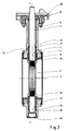
- the general butterfly valve structure as shown in FIGS. 1 and 2, comprises a valve body 1 provided with a main bore 2 for the passage of fluid which can be closed off by a butterfly valve 3 mounted to rotate along a transverse axis I-I.
- the butterfly 3 is integral with a control shaft 4 rotatably mounted along the transverse axis I-I and housed in a transverse bore 5 corresponding to the body 1.
- Means 6 for fixing clamps and fixing a control head with extension 20 are adapted on the body 1 at the end of the transverse bore 5.
- the control shaft 4 is held in a bearing constituted by an attached ring 7 interposed between the shaft 4 and the body 1 in the transverse bore 5.
- the transverse bore 5 of the valve body 1 is rough cast, the whole of the valve body 1 being produced by molding.
- the ring 7 forming a bearing comprises an internal bore 8 whose dimension is closely adapted to that of the control shaft 4.
- the external surface 9 of the ring 7 must be able to adapt to slightly different sizes from the transverse bore 5 of the body 1, as a function of the relatively large dimensional tolerances of this transverse bore 5 resulting from the foundry processes.
- the peripheral outer surface 9 of the ring 7 is grooved in longitudinal or helical grooves.
- a ring 7 comprising a tubular cylindrical portion 10 limited by a cylindrical inner surface of smooth revolution forming the bore 8 of the ring, and limited by an outer surface 9 grooved to longitudinal grooves.
- the cylindrical portion 10 is extended by an annular shoulder 11 limiting the depression of the ring 7 in the transverse bore 5 by coming to bear against a corresponding shoulder of the body 1, as shown in Figure 2.
- a seal 12 can advantageously be interposed between the internal transverse bore wall 5 of the body 1 and the control shaft 4, in a housing formed between the ring 7 and a shoulder 13 of the body 1.
- a cuff 14 made of elastomer seals between the body 1 and the butterfly 3.
- the throttle valve 3 is held on one side by the control shaft 4, and on the opposite side by a rear axle 15 engaged in a similar manner in a second transverse bore 16 of the body 1 coaxial with the first transverse bore 5.
- a second ring 17 is interposed between the rear axle 15 and the second transverse bore 16, this second ring 17 may be similar to the first ring 7.
- a seal 18 can also be interposed between the body 1 and the rear axle 15 in a similar manner to the first seal 12.
- a plug 19 can seal the end of the second transverse bore 16.
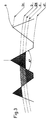
- the teeth of the grooves formed on the outer surface 9 of the ring 7 can have different profiles, and their size is a function of the dimensional tolerances of the transverse bore 5 which it is desired to compensate for by the ring 7.
- FIG. 3 there is shown a profile possible triangular fluted teeth with truncated base.
- a tooth head diameter D1 a tooth foot diameter d1
- a maximum admissible diameter D of the transverse bore 5 receiving the ring 7 a minimum admissible diameter d for the transverse bore 5 receiving the ring 7
- a nominal diameter DN of the transverse bore 5 a nominal diameter of the transverse bore 5.
- the average angle A formed by the inclined flanks of the teeth can advantageously be between 30 and 60 degrees; the diameter D1 can be between 1.0075 D and 1.0112 D; the diameter d1 of the tooth root can advantageously be between 0.9849 d and 0.09886 d.
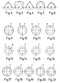
- the teeth of the grooves can admit relatively varied profiles, which each have their advantages and disadvantages.
- Figure 4 shows a triangular profile with a truncated top
- FIG. 5 represents a profile with parallel sides and slightly curved top
- Figure 6 is a triangular profile like that of Figure 3
- Figure 7 is a profile with parallel sides and circular apex
- Figure 8 shows an involute profile.
- the teeth are distributed over six zones offset each by 60 degrees, the external surface 9 of ring 7 thus being formed of a cylindrical surface of revolution with six serrated zones with prominent teeth.
- the outer surface 9 of ring 7 is a cylindrical surface of revolution with four serrated zones with prominent teeth, the zones being offset by 90 degrees.
- the external surface 9 of the ring 7 comprises three zones with prominent teeth offset by 120 degrees.
- the internal bore 8 of the ring 7 can either be a cylindrical surface of revolution as shown in FIG. 13 or FIGS. 23 and 24, or a surface itself grooved with much wider grooves as shown for example in Figures 14 to 16.
- the grooves of the inner bore 8 are not intended to be crushed, but constitute a dimensionally rigid surface for the correct maintenance of the control shaft 4.
- FIGS. 9 to 12 It is possible to combine each of the tooth distributions of FIGS. 9 to 12 with any of the interior bore shapes of FIGS. 13 to 16.
- FIGS. 17 to 21 illustrate some possible modes of combination according to the invention.
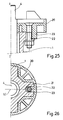
- control head fixing means for controlling the rotation of the shaft 4.
- these control head fixing means must traditionally adapt in axial bores of the body 1, and the bores are produced by machining so that they are of sufficiently precise dimensions.
- control head fixing means comprising an extension 20, comprise at least two diametrically opposite lateral notches 21, open laterally outwards, for example radially with respect to axis II of body 1, and shaped in body 1 to receive fixing bolts such as bolt 22 parallel to axis II.
- the extension 20 itself comprises protuberances 23 which are received in the notch 21 to close the lateral opening of said notch 21, thus surrounding the screw of the bolt 22 in its passage through the corresponding notch 21 and ensuring its guidance axial. In this way, the notch 21 can be made as a rough casting in the body 1.
- the body 1 can in particular be made of metal cast by the traditional foundry methods, or in other molded materials.
Landscapes
- Engineering & Computer Science (AREA)
- General Engineering & Computer Science (AREA)
- Mechanical Engineering (AREA)
- Lift Valve (AREA)
- Valve Housings (AREA)
Applications Claiming Priority (2)
| Application Number | Priority Date | Filing Date | Title |
|---|---|---|---|
| FR9206581A FR2691780B1 (fr) | 1992-05-26 | 1992-05-26 | Vanne papillon a corps brut de fonderie. |
| FR9206581 | 1992-05-26 |
Publications (2)
| Publication Number | Publication Date |
|---|---|
| EP0572334A1 true EP0572334A1 (de) | 1993-12-01 |
| EP0572334B1 EP0572334B1 (de) | 1996-10-30 |
Family
ID=9430292
Family Applications (1)
| Application Number | Title | Priority Date | Filing Date |
|---|---|---|---|
| EP93420206A Expired - Lifetime EP0572334B1 (de) | 1992-05-26 | 1993-05-21 | Klappenventil mit rohem Giessgehäuse |
Country Status (4)
| Country | Link |
|---|---|
| EP (1) | EP0572334B1 (de) |
| AT (1) | ATE144816T1 (de) |
| DE (1) | DE69305689T2 (de) |
| FR (1) | FR2691780B1 (de) |
Families Citing this family (1)
| Publication number | Priority date | Publication date | Assignee | Title |
|---|---|---|---|---|
| CN103899773B (zh) * | 2014-03-11 | 2017-01-04 | 国家电网公司 | 一种用于电力变压器油箱的防漏油阀门 |
Citations (3)
| Publication number | Priority date | Publication date | Assignee | Title |
|---|---|---|---|---|
| FR1070098A (fr) * | 1952-11-25 | 1954-07-16 | Aeroquip Corp | Coussinet avec zone de guidage rectifiée et zone de mandrinage |
| DE2411907A1 (de) * | 1973-03-15 | 1974-09-19 | Magneti Marelli Spa | Verbesserung an lagerausbildungen fuer drehende wellen aus poroesen, gesinterten lagerschalen |
| FR2462630A1 (fr) * | 1979-07-27 | 1981-02-13 | Crane Co | Vanne dont le papillon d'obturation coopere avec un siege reglable |
-
1992
- 1992-05-26 FR FR9206581A patent/FR2691780B1/fr not_active Expired - Fee Related
-
1993
- 1993-05-21 DE DE69305689T patent/DE69305689T2/de not_active Expired - Fee Related
- 1993-05-21 AT AT93420206T patent/ATE144816T1/de not_active IP Right Cessation
- 1993-05-21 EP EP93420206A patent/EP0572334B1/de not_active Expired - Lifetime
Patent Citations (3)
| Publication number | Priority date | Publication date | Assignee | Title |
|---|---|---|---|---|
| FR1070098A (fr) * | 1952-11-25 | 1954-07-16 | Aeroquip Corp | Coussinet avec zone de guidage rectifiée et zone de mandrinage |
| DE2411907A1 (de) * | 1973-03-15 | 1974-09-19 | Magneti Marelli Spa | Verbesserung an lagerausbildungen fuer drehende wellen aus poroesen, gesinterten lagerschalen |
| FR2462630A1 (fr) * | 1979-07-27 | 1981-02-13 | Crane Co | Vanne dont le papillon d'obturation coopere avec un siege reglable |
Also Published As
| Publication number | Publication date |
|---|---|
| DE69305689T2 (de) | 1997-05-28 |
| EP0572334B1 (de) | 1996-10-30 |
| FR2691780B1 (fr) | 1995-07-13 |
| DE69305689D1 (de) | 1996-12-05 |
| ATE144816T1 (de) | 1996-11-15 |
| FR2691780A1 (fr) | 1993-12-03 |
Similar Documents
| Publication | Publication Date | Title |
|---|---|---|
| CA2082301C (fr) | Joint verrouille pour canalisations | |
| EP0182676B1 (de) | Universelles Klappenventil und Verfahren zu dessen Herstellung | |
| FR2947592A1 (fr) | Dispositif de liaison mecanique d'au moins deux pieces a alesages coaxiaux | |
| EP0870967A1 (de) | Feste Verbindung für Rohrleitungen und geschlitzter Metallring zur Verwendung in einer solchen Verbindung | |
| EP0019496B1 (de) | Drosselklappe und Verfahren zu ihrer Herstellung | |
| FR3006029A1 (fr) | Ensemble pour la realisation d'un joint filete pour le forage et l'exploitation des puits d'hydrocarbures et joint filete resultant | |
| FR2657939A1 (fr) | Raccord etanche perfectionne pour conduites de transport d'un fluide quelconque. | |
| FR2712038A1 (fr) | Moteur oscillant hydraulique, et son procédé de montage. | |
| EP0526373B1 (de) | Verriegelbare Rohrverbindung mit Abdichtanordnung aus einem Verbundwerkstoff | |
| EP2347140A1 (de) | Ring für ein hydrostatisches und hydrodynamisches lager, mit solch einem ring versehene hydraulische maschine und verfahren zur befestigung solch eines rings auf einer welle | |
| CH619522A5 (de) | ||
| EP0572334B1 (de) | Klappenventil mit rohem Giessgehäuse | |
| FR2836955A1 (fr) | Systeme de commande des soupapes pour un moteur a combustion interne | |
| EP0027765A1 (de) | Kugelhahn und Verfahren zu dessen Herstellung | |
| EP3770472B1 (de) | Perfektioniertes drosselventil für den transport von fluiden unter hohem oder extremem druck | |
| FR2511751A1 (fr) | Raccord pour une conduite d'injection de carburant sous pression mettant en communication une pompe d'injection et un injecteur | |
| FR2664351A3 (fr) | Vanne papillon. | |
| FR2665509A1 (fr) | Collerette rapportee pour joint entre elements de tuyauterie, et ensemble pour tuyauterie comportant une telle collerette. | |
| EP4059467A1 (de) | Transmukosale basis mit verbessertem längsdurchgang | |
| FR3007495A1 (fr) | Ensemble pour la realisation d'un joint filete pour le forage et l'exploitation des puits d'hydrocarbures, joint filete et procede de realisation d'un tel joint | |
| EP1671811A1 (de) | Leichtrad insbesondere für landwirtschaftliche Maschinen | |
| EP0791490A1 (de) | Reifenventil mit elliptischem Sitz | |
| EP4007863B1 (de) | Tankverschlussvorrichtung und tank | |
| FR2461874A1 (fr) | Raccord pour canalisations souples ou semi-rigides | |
| FR3132555A1 (fr) | Elément femelle de raccord fluidique et raccord fluidique comprenant un tel élément |
Legal Events
| Date | Code | Title | Description |
|---|---|---|---|
| PUAI | Public reference made under article 153(3) epc to a published international application that has entered the european phase |
Free format text: ORIGINAL CODE: 0009012 |
|
| AK | Designated contracting states |
Kind code of ref document: A1 Designated state(s): AT BE CH DE DK ES FR GB GR IT LI LU NL PT SE |
|
| 17P | Request for examination filed |
Effective date: 19931217 |
|
| 17Q | First examination report despatched |
Effective date: 19950302 |
|
| GRAG | Despatch of communication of intention to grant |
Free format text: ORIGINAL CODE: EPIDOS AGRA |
|
| GRAH | Despatch of communication of intention to grant a patent |
Free format text: ORIGINAL CODE: EPIDOS IGRA |
|
| GRAH | Despatch of communication of intention to grant a patent |
Free format text: ORIGINAL CODE: EPIDOS IGRA |
|
| GRAA | (expected) grant |
Free format text: ORIGINAL CODE: 0009210 |
|
| AK | Designated contracting states |
Kind code of ref document: B1 Designated state(s): AT BE CH DE DK ES FR GB GR IT LI LU NL PT SE |
|
| PG25 | Lapsed in a contracting state [announced via postgrant information from national office to epo] |
Ref country code: NL Free format text: LAPSE BECAUSE OF FAILURE TO SUBMIT A TRANSLATION OF THE DESCRIPTION OR TO PAY THE FEE WITHIN THE PRESCRIBED TIME-LIMIT Effective date: 19961030 Ref country code: IT Free format text: LAPSE BECAUSE OF FAILURE TO SUBMIT A TRANSLATION OF THE DESCRIPTION OR TO PAY THE FEE WITHIN THE PRE;WARNING: LAPSES OF ITALIAN PATENTS WITH EFFECTIVE DATE BEFORE 2007 MAY HAVE OCCURRED AT ANY TIME BEFORE 2007. THE CORRECT EFFECTIVE DATE MAY BE DIFFERENT FROM THE ONE RECORDED.SCRIBED TIME-LIMIT Effective date: 19961030 Ref country code: GR Free format text: LAPSE BECAUSE OF FAILURE TO SUBMIT A TRANSLATION OF THE DESCRIPTION OR TO PAY THE FEE WITHIN THE PRESCRIBED TIME-LIMIT Effective date: 19961030 Ref country code: ES Free format text: THE PATENT HAS BEEN ANNULLED BY A DECISION OF A NATIONAL AUTHORITY Effective date: 19961030 Ref country code: DK Effective date: 19961030 Ref country code: AT Effective date: 19961030 |
|
| REF | Corresponds to: |
Ref document number: 144816 Country of ref document: AT Date of ref document: 19961115 Kind code of ref document: T |
|
| REF | Corresponds to: |
Ref document number: 69305689 Country of ref document: DE Date of ref document: 19961205 |
|
| PG25 | Lapsed in a contracting state [announced via postgrant information from national office to epo] |
Ref country code: SE Effective date: 19970130 Ref country code: PT Effective date: 19970130 |
|
| REG | Reference to a national code |
Ref country code: CH Ref legal event code: NV Representative=s name: ZIMMERLI, WAGNER & PARTNER AG |
|
| GBT | Gb: translation of ep patent filed (gb section 77(6)(a)/1977) |
Effective date: 19970203 |
|
| NLV1 | Nl: lapsed or annulled due to failure to fulfill the requirements of art. 29p and 29m of the patents act | ||
| PLBE | No opposition filed within time limit |
Free format text: ORIGINAL CODE: 0009261 |
|
| STAA | Information on the status of an ep patent application or granted ep patent |
Free format text: STATUS: NO OPPOSITION FILED WITHIN TIME LIMIT |
|
| 26N | No opposition filed | ||
| PGFP | Annual fee paid to national office [announced via postgrant information from national office to epo] |
Ref country code: BE Payment date: 19980512 Year of fee payment: 6 |
|
| PGFP | Annual fee paid to national office [announced via postgrant information from national office to epo] |
Ref country code: GB Payment date: 19980518 Year of fee payment: 6 |
|
| PGFP | Annual fee paid to national office [announced via postgrant information from national office to epo] |
Ref country code: FR Payment date: 19980519 Year of fee payment: 6 |
|
| PGFP | Annual fee paid to national office [announced via postgrant information from national office to epo] |
Ref country code: DE Payment date: 19980724 Year of fee payment: 6 |
|
| PGFP | Annual fee paid to national office [announced via postgrant information from national office to epo] |
Ref country code: CH Payment date: 19980818 Year of fee payment: 6 |
|
| PGFP | Annual fee paid to national office [announced via postgrant information from national office to epo] |
Ref country code: LU Payment date: 19980922 Year of fee payment: 6 |
|
| PG25 | Lapsed in a contracting state [announced via postgrant information from national office to epo] |
Ref country code: LU Free format text: LAPSE BECAUSE OF NON-PAYMENT OF DUE FEES Effective date: 19990521 Ref country code: GB Free format text: LAPSE BECAUSE OF NON-PAYMENT OF DUE FEES Effective date: 19990521 |
|
| PG25 | Lapsed in a contracting state [announced via postgrant information from national office to epo] |
Ref country code: LI Free format text: LAPSE BECAUSE OF NON-PAYMENT OF DUE FEES Effective date: 19990531 Ref country code: CH Free format text: LAPSE BECAUSE OF NON-PAYMENT OF DUE FEES Effective date: 19990531 Ref country code: BE Free format text: LAPSE BECAUSE OF NON-PAYMENT OF DUE FEES Effective date: 19990531 |
|
| BERE | Be: lapsed |
Owner name: S.A. OREG Effective date: 19990531 |
|
| REG | Reference to a national code |
Ref country code: CH Ref legal event code: PL |
|
| GBPC | Gb: european patent ceased through non-payment of renewal fee |
Effective date: 19990521 |
|
| PG25 | Lapsed in a contracting state [announced via postgrant information from national office to epo] |
Ref country code: FR Free format text: LAPSE BECAUSE OF NON-PAYMENT OF DUE FEES Effective date: 20000131 |
|
| PG25 | Lapsed in a contracting state [announced via postgrant information from national office to epo] |
Ref country code: DE Free format text: LAPSE BECAUSE OF NON-PAYMENT OF DUE FEES Effective date: 20000301 |
|
| REG | Reference to a national code |
Ref country code: FR Ref legal event code: ST |