EP0572312B1 - Dichtungseinrichtung zwischen Statorschaufelnstufen und einer Drehtrommel - Google Patents
Dichtungseinrichtung zwischen Statorschaufelnstufen und einer Drehtrommel Download PDFInfo
- Publication number
- EP0572312B1 EP0572312B1 EP93401334A EP93401334A EP0572312B1 EP 0572312 B1 EP0572312 B1 EP 0572312B1 EP 93401334 A EP93401334 A EP 93401334A EP 93401334 A EP93401334 A EP 93401334A EP 0572312 B1 EP0572312 B1 EP 0572312B1
- Authority
- EP
- European Patent Office
- Prior art keywords
- grooves
- seals
- rings
- transverse faces
- blades
- Prior art date
- Legal status (The legal status is an assumption and is not a legal conclusion. Google has not performed a legal analysis and makes no representation as to the accuracy of the status listed.)
- Expired - Lifetime
Links
- 238000007789 sealing Methods 0.000 title description 3
- 230000002787 reinforcement Effects 0.000 claims 2
- 210000003462 vein Anatomy 0.000 description 12
- 239000007789 gas Substances 0.000 description 8
- 239000000463 material Substances 0.000 description 6
- 239000011324 bead Substances 0.000 description 5
- 239000000969 carrier Substances 0.000 description 3
- 238000006073 displacement reaction Methods 0.000 description 3
- 238000005452 bending Methods 0.000 description 2
- 230000000694 effects Effects 0.000 description 2
- OKTJSMMVPCPJKN-UHFFFAOYSA-N Carbon Chemical compound [C] OKTJSMMVPCPJKN-UHFFFAOYSA-N 0.000 description 1
- 229910052799 carbon Inorganic materials 0.000 description 1
- 239000002131 composite material Substances 0.000 description 1
- 230000006835 compression Effects 0.000 description 1
- 238000007906 compression Methods 0.000 description 1
- 238000013461 design Methods 0.000 description 1
- 239000013013 elastic material Substances 0.000 description 1
- 230000003628 erosive effect Effects 0.000 description 1
- 238000003780 insertion Methods 0.000 description 1
- 230000037431 insertion Effects 0.000 description 1
- 238000012797 qualification Methods 0.000 description 1
- 230000001846 repelling effect Effects 0.000 description 1
- 230000003068 static effect Effects 0.000 description 1
- 238000012360 testing method Methods 0.000 description 1
Images
Classifications
-
- F—MECHANICAL ENGINEERING; LIGHTING; HEATING; WEAPONS; BLASTING
- F01—MACHINES OR ENGINES IN GENERAL; ENGINE PLANTS IN GENERAL; STEAM ENGINES
- F01D—NON-POSITIVE DISPLACEMENT MACHINES OR ENGINES, e.g. STEAM TURBINES
- F01D11/00—Preventing or minimising internal leakage of working-fluid, e.g. between stages
- F01D11/001—Preventing or minimising internal leakage of working-fluid, e.g. between stages for sealing space between stator blade and rotor
-
- F—MECHANICAL ENGINEERING; LIGHTING; HEATING; WEAPONS; BLASTING
- F05—INDEXING SCHEMES RELATING TO ENGINES OR PUMPS IN VARIOUS SUBCLASSES OF CLASSES F01-F04
- F05D—INDEXING SCHEME FOR ASPECTS RELATING TO NON-POSITIVE-DISPLACEMENT MACHINES OR ENGINES, GAS-TURBINES OR JET-PROPULSION PLANTS
- F05D2240/00—Components
- F05D2240/55—Seals
- F05D2240/56—Brush seals
-
- Y—GENERAL TAGGING OF NEW TECHNOLOGICAL DEVELOPMENTS; GENERAL TAGGING OF CROSS-SECTIONAL TECHNOLOGIES SPANNING OVER SEVERAL SECTIONS OF THE IPC; TECHNICAL SUBJECTS COVERED BY FORMER USPC CROSS-REFERENCE ART COLLECTIONS [XRACs] AND DIGESTS
- Y02—TECHNOLOGIES OR APPLICATIONS FOR MITIGATION OR ADAPTATION AGAINST CLIMATE CHANGE
- Y02T—CLIMATE CHANGE MITIGATION TECHNOLOGIES RELATED TO TRANSPORTATION
- Y02T50/00—Aeronautics or air transport
- Y02T50/60—Efficient propulsion technologies, e.g. for aircraft
Definitions
- the invention relates to a device for sealing between stages of blades and a drum rotating relative to them such a device is described in document FR-A-379 209. It can in particular find use in engine compressors plane.
- Such machines include a drum-shaped rotor which a stator surrounds to delimit with it an annular stream of gas flow. This vein is occupied by stages of movable vanes, rotating with the rotor, which alternate with stages of fixed vanes linked to the stator and intended for rectifying the flow of gases after their passage through the stages movable blades inclined to the side.
- the fixed vanes should extend almost over the entire thickness of the annular vein in order to prevent gases from escaping between the edge of the blades and the rotor, but the operating conditions of the engine and in particular, the temperatures vary greatly in the different operating regimes and different thermal expansions could cause friction with the catastrophic consequences of the rotor on the edges of the fixed blades. It is therefore necessary to accept a minimum clearance at this location, which implies relatively large yield losses.
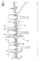
- FIG. 1 A design adopted in an effectively constructed engine is believed to give better results by almost entirely preventing leakage. It is shown in Figure 1.
- the fixed blades 1 of each stage have their edge edges 2 joined by a ring 3.
- the rotor 4 rotating around the axis X is then composed of a ferrule 5 whose generator is practically rectilinear - in order to avoid the concentrations of constraints - and on which are established circular beads 6 which contain the recesses 7 adapted to the insertion of the feet 8 of the movable blades 9.
- Recesses 10 extend between the beads 6 consecutive, and the rings 3 are flush with their mouth so as to form with the external faces 11 of the beads 6 a substantially smooth and continuous surface which allows a regular flow in the vein.
- each recess 10 carries wipers 12, that is to say circular ridges directed towards the rings 3; the latter are covered with an easy-to-wear material 13 which may be a honeycomb structure.
- the height of the wipers 12 and the thickness of the wear material 13 are chosen so that the wipers 12 rub on the wear material 13 and erode it when the engine is running so as to form a labyrinth seal where the games are very small. One should thus avoid practically any gas circulation through the recesses 10.
- the invention is essentially original in that the seals carried by the rings extend to the transverse faces of the recesses. More precisely, it consists of stages of blades in an annular gas flow stream and of a drum partially delimiting the stream and rotating with respect to the blades around an axis coinciding with a longitudinal direction of the stream, the blade stages being terminated by rings which are flush with circular recesses of the drum bounded by two transverse faces, the rings carrying two circular grooves each housing a joint, and it is characterized in that the grooves are open towards one of the faces respective transverse and are provided with means for pushing the seals out of the grooves and pressing them on the transverse faces.
- the joints are preferably located as close as possible to the walls delimiting the annular vein, so as not to produce there too great variations of the sections generating turbulence. They are pushed back by means such as springs (in particular with circular leaf) towards the transverse faces with a sufficiently weak force to avoid excessive friction and the corresponding wear, and a sufficient flexibility so that the effect of the variations of the longitudinal positions between fixed and moving parts is insensitive. As for the radial variations, they have no influence since the joint simply slides on the transverse faces.
- the means for repelling the seals are flexible and elastic bristles compressed between seal holders sliding in the grooves and to which the seals are fixed and the bottoms of the grooves.
- the flexible and elastic bristles can then conveniently constitute the joints and extend to the transverse faces.
- Circular seals are already known and subjected to a longitudinal force in this technical field, but these are rigid seals with two concentric lips defining a chamber which must be supplied with gas under pressure so that the lips do not rub on the transverse face in front of which they extend. Larger leaks than in the invention are therefore inevitable, and the supply of pressurized gas for each of these joints represents an expensive arrangement.
- the invention can be improved by removable stops carried by the rings to retain the seal in the grooves in certain operating states, in particular during the engine qualification tests.
- the rings will be composed of two parts movable mutually in the longitudinal direction of the vein, one being fixed to the blades and the other bearing the grooves and the joints.
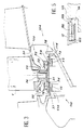
- the recesses 10 in FIG. 2 have a smooth and flat bottom, devoid of wipers, and are limited by two transverse planar and circular transverse faces 14 of the beads 6.
- the rings 3 essentially consist of plates 16 which extend in front of the recesses 10 and almost as far as the transverse faces 14.
- the fixed blades 1 are connected to their external faces, and their internal faces carry collars 15 which occupy a part recesses 10 and can be in one piece with the plates 16 or welded to them.
- the original shape of the collars 15 is rectilinear and oblique in order to deviate quite clearly from the plates 16, as the dotted lines show; they are then deformed, during assembly of the machine, in order to be brought closer to the plates 16 and to form with them circular grooves 17 which open towards the transverse faces 14.
- the grooves 17 each receive a seal carrier 18 with cross-section U which contains a circular joint 19 the free end of which protrudes from the joint carrier 18 and the respective groove 17 to rub against one of the transverse faces 14.
- This is obtained by means of leaf springs 20 slid in the grooves 17 between their bottom 22 and bottom 21 of the seal carriers 18.
- the force of application of the seals 19 on the transverse faces 14 is defined by the dimensions of the parts and the stiffness of the springs 20.
- the plates 16 have a longitudinal edge 23 which protrudes from the longitudinal edge 24 of collars 15. If the pressure in the annular vein is high, it is advisable to reverse this relationship so that the collars 15 support the seal carriers 18 well.
- Known means such as removable headless screws 27 engaged in holes in the plates 16 and the end of which penetrates into a longitudinal groove 28 of a seal holder 18 prevent the latter from rotating in the grooves 17.
- the grooves 28 can also serve as a longitudinal stop means to prevent the seals 19 from coming out too much from the grooves 17. It is then sufficient to limit their length accordingly so that the grub screw 27 abuts against their end.
- seal holders 18, the seals 19 and the leaf springs 20 are divided into sectors to allow the mounting of the machine.
- the intervals 25 between seal carrier and seals are then offset from those 26 which separate the plates 16 in order to avoid at these locations, the communications between the annular vein and the recesses 10.
- Other means, and in particular of other seals are possible to plug the parts of the gaps 26 between the sectors of the rings 3 which are located between the pairs of grooves 17.
- the seals 19 may for example be made of carbon, composite, metallic braid, lamellae, brush . Other known materials are conceivable. The choice is wide because they are mounted flexibly and with limited movement and are therefore not pressed against the transverse faces 14 with a force which would wear them out prematurely.
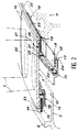
- Figures 3 and 4 show two other embodiments of the invention where the rings are referenced by 103 and 203. They consist of two parts: a part 30 linked to the fixed blades 1 and a part 31 which carries the collars 15 and the seals 19. These two parts 30 and 31 are movable with one another in the longitudinal direction of the annular vein. To this end, the second part 31 is provided with angles 32 which hold against them sliding tubes 33 of the first part 30 while allowing the sliding tubes 33 to sink into their crevices and partially exit therefrom. Grooves 34 are provided between the two parts 30 and 31 to prevent them from rotating relative to each other.
- the recesses 110 are here deeper and the rings 103, and more precisely their first part 30, have a large radial extension because the fixed vanes 1 are pivotally mounted so that their inclination can be varied according to the speed of the machine.
- the tilt control mechanism is placed around the stages of fixed blades 1 and therefore does not appear in the figures.
- the rings 103 only comprise means for permitting the pivoting of the fixed vanes 1.
- the first parts 30 are therefore arranged accordingly and contain an anti-friction bushing surrounding the pivot axis 36 of the fixed vanes 1.
- the transverse faces 114 of the rotor 104 on which the seals 19 rub are not established in the immediate vicinity of the annular vein but at some radial distance from the latter, on circular projections 37 or 38 of radial orientation and which can be directed towards the inside or outside as appropriate.
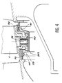
- the device of FIG. 4 is a little different: we choose to bring the seals 19 close to the annular vein, so that the movable part which carries the rings 203 consists of an inner plate 40 and two rings with seal carrier 41 which extend up to the pivot axis 36.
- a sliding system of the movable part 39 with respect to the fixed part 42 of the rings 203, constructed practically like the part 30, also makes it possible to compensate for deformations in the machine to establish an identical force on the two seals 19.
- seals of a different kind than those of FIG. 2, which they can replace are seals of a different kind than those of FIG. 2, which they can replace.
- the springs 20 are omitted and the seals 119 are here composed of an edge of flexible bristles fixed to the seal holders 118, one edge 121 of which rubs on the transverse faces 14 and the other edge 122 of which touches the bottom of the grooves 17 (the seal 19 of the example of FIG. 2 could consist of other products and in particular of continuous lips of flexible and elastic material).
- the seal carriers 118 here again slide freely in the grooves 17.
- the gas flows from the inside of the grooves are thwarted by the edge 122 which acts as a static seal, it is possible to reduce the compression of the bristles by cutting the desired length of their ends before mounting them in the grooves 17, and the axial displacements of the rotor in the stator have repercussions on the joints by a bending of the bristles which produces an elastic force varying relatively little according to the extent of the bending, unlike what happens for many springs usual. The importance of this effort depends in particular on the free length of the bristles on the edge side 122.
Landscapes
- Engineering & Computer Science (AREA)
- Mechanical Engineering (AREA)
- General Engineering & Computer Science (AREA)
- Sealing Devices (AREA)
- Turbine Rotor Nozzle Sealing (AREA)
- Sealing Using Fluids, Sealing Without Contact, And Removal Of Oil (AREA)
Claims (9)
- Vorrichtung bestehend aus Schaufelstufen (1) in einem ringförmigen Gasausflußstrom und einer Trommel (4,104), die teilweise den Strom begrenzt und sich bezüglich der Schaufeln (1) um eine Achse (X) dreht, die mit einer Längsrichtung des Stroms zusammenfällt, wobei die Schaufelstufen in Ringen (3,103,203) enden, die in den ringförmigen Verstärkungen der Trommel anliegen, die durch zwei Querseiten (14,114) begrenzt sind, und die Ringe zwei ringförmige Nuten (17) aufweisen, die jeweils eine Dichtung (19) aufnehmen,
dadurch gekennzeichnet,
daß die Nuten in Richtung einer jeweiligen der Querseiten offen sind und mit Mitteln (20,122) zum Drücken der Dichtungen aus den Nuten heraus und zum Andrücken an die Querseiten versehen sind. - Vorrichtung nach Anspruch 1,
dadurch gekennzeichnet,
daß die Mittel zum Herausdrücken der Dichtungen Blattfedern (20) sind, die sich am Grund (22) der Nuten (17) befinden. - Vorrichtung nach einem der Ansprüche 1 oder 2,
dadurch gekennzeichnet,
daß die Ringe lösbare Anschläge (27,28) zum Zurückhalten der Dichtungen (19) in den Nuten (17) tragen. - Vorrichtung nach einem der Ansprüche 1 bis 4,
dadurch gekennzeichnet,
daß die Nuten durch zwei Ränder (23,24) mit unterschiedlicher Höhe begrenzt sind. - Vorrichtung nach einem der Ansprüche 1 bis 4,
dadurch gekennzeichnet,
daß die Ringe umgebogene Borte (15) aufweisen, die sich in den Verstärkungen zur Bildung der Ränder der Nuten befinden. - Vorrichtung nach einem der Ansprüche 1 bis 5,
dadurch gekennzeichnet,
daß die Ringe aus zwei Abschnitten (30,31,39,42) gebildet sind, die gegeneinander in der Längsrichtung des Stroms beweglich sind, wobei der eine an den Schaufeln befestigt ist und der andere Nuten trägt. - Vorrichtung nach einem der Ansprüche 1 bis 6,
dadurch gekennzeichnet,
daß die Schaufeln drehbar auf den Ringen angebracht sind. - Vorrichtung nach einem der Ansprüche 1 bis 7,
dadurch gekennzeichnet,
daß die Mittel zum Drücken der Ringe weiche und elastische Haar-Elemente sind, die zwischen Dichtungsträgern (118), die in den Nuten (17) verschiebbar sind und an denen die Dichtungen (119) befestigt sind, und in den Gründen der Nuten (17) eingequetscht sind. - Vorrichtung nach Anspruch 8,
dadurch gekennzeichnet,
daß die weichen und elastischen Haar-Elemente die Dichtungen (119) bilden und sich bis zu den Querseiten (14) erstrecken.
Applications Claiming Priority (2)
| Application Number | Priority Date | Filing Date | Title |
|---|---|---|---|
| FR9206475 | 1992-05-27 | ||
| FR9206475A FR2691749B1 (fr) | 1992-05-27 | 1992-05-27 | Dispositif d'etancheite entre des etages d'aubes et un tambour tournant notamment pour eviter les fuites autour des etages d'aubes de redresseur . |
Publications (2)
| Publication Number | Publication Date |
|---|---|
| EP0572312A1 EP0572312A1 (de) | 1993-12-01 |
| EP0572312B1 true EP0572312B1 (de) | 1995-10-11 |
Family
ID=9430228
Family Applications (1)
| Application Number | Title | Priority Date | Filing Date |
|---|---|---|---|
| EP93401334A Expired - Lifetime EP0572312B1 (de) | 1992-05-27 | 1993-05-25 | Dichtungseinrichtung zwischen Statorschaufelnstufen und einer Drehtrommel |
Country Status (5)
| Country | Link |
|---|---|
| US (1) | US5328328A (de) |
| EP (1) | EP0572312B1 (de) |
| JP (1) | JP2620493B2 (de) |
| DE (1) | DE69300621T2 (de) |
| FR (1) | FR2691749B1 (de) |
Families Citing this family (24)
| Publication number | Priority date | Publication date | Assignee | Title |
|---|---|---|---|---|
| FR2708311B1 (fr) * | 1993-07-28 | 1995-09-01 | Snecma | Stator de turbomachine à aubes pivotantes et anneau de commande. |
| US5522698A (en) * | 1994-04-29 | 1996-06-04 | United Technologies Corporation | Brush seal support and vane assembly windage cover |
| FR2724412B1 (fr) | 1994-09-14 | 1996-10-25 | Snecma | Aube de turbomachine en materiau composite munie d'un joint d'etancheite et son procede de realisation |
| US5609469A (en) * | 1995-11-22 | 1997-03-11 | United Technologies Corporation | Rotor assembly shroud |
| US6042334A (en) * | 1998-08-17 | 2000-03-28 | General Electric Company | Compressor interstage seal |
| DE19848103A1 (de) * | 1998-10-19 | 2000-04-20 | Asea Brown Boveri | Dichtungsanordnung |
| US6347508B1 (en) | 2000-03-22 | 2002-02-19 | Allison Advanced Development Company | Combustor liner support and seal assembly |
| US7093835B2 (en) * | 2002-08-27 | 2006-08-22 | United Technologies Corporation | Floating brush seal assembly |
| US6814538B2 (en) | 2003-01-22 | 2004-11-09 | General Electric Company | Turbine stage one shroud configuration and method for service enhancement |
| DE102005042272A1 (de) * | 2005-09-06 | 2007-03-08 | Mtu Aero Engines Gmbh | Strömungsmaschine sowie Dichtungselement für eine Strömungsmaschine |
| US20070132190A1 (en) * | 2005-12-12 | 2007-06-14 | Charles Trabert | Axial dynamic brush seal |
| GB2438858B (en) * | 2006-06-07 | 2008-08-06 | Rolls Royce Plc | A sealing arrangement in a gas turbine engine |
| GB2439089A (en) * | 2006-06-15 | 2007-12-19 | Alstom Technology Ltd | A brush seal for sealing a gap in a turbomachine |
| US20080095616A1 (en) * | 2006-10-20 | 2008-04-24 | Ioannis Alvanos | Fluid brush seal with segment seal land |
| DE102007010378A1 (de) * | 2007-03-03 | 2008-09-04 | Mtu Aero Engines Gmbh | Dichtelement zur Abdichtung eines Spaltes zwischen Stator und Rotor einer axialen Strömungsmaschine |
| FR2928961B1 (fr) * | 2008-03-19 | 2015-11-13 | Snecma | Distributeur sectorise pour une turbomachine. |
| KR101105402B1 (ko) * | 2009-09-30 | 2012-01-17 | 한국전력공사 | 용접비드 방식을 적용한 가스터빈 디스크 밀봉밴드 |
| US8777563B2 (en) * | 2011-01-31 | 2014-07-15 | General Electric Company | Axial brush seal |
| US20120321437A1 (en) * | 2011-06-17 | 2012-12-20 | General Electric Company | Turbine seal system |
| EP2843196B1 (de) * | 2013-09-03 | 2020-04-15 | Safran Aero Boosters SA | Verdichter einer turbomaschine und zugehörige turbomaschine |
| FR3010462B1 (fr) * | 2013-09-11 | 2021-10-08 | Snecma | Secteur angulaire de redresseur pour compresseur de turbomachine comportant un joint d'etancheite a brosse |
| DE102013220276A1 (de) | 2013-10-08 | 2015-04-09 | MTU Aero Engines AG | Strömungsmaschine |
| BE1025092B1 (fr) * | 2017-03-31 | 2018-10-29 | Safran Aero Boosters S.A. | Joint a brosse pour rotor de turbomachine |
| US10465546B2 (en) * | 2017-08-28 | 2019-11-05 | United Technologies Corporation | Brush seal with extended backing plate |
Family Cites Families (11)
| Publication number | Priority date | Publication date | Assignee | Title |
|---|---|---|---|---|
| FR358410A (fr) * | 1905-05-02 | 1906-02-15 | George Westinghouse | Perfectionnements dans les turbines à fluide sous pression |
| FR379209A (fr) * | 1906-07-03 | 1907-10-29 | Sebastian Ziani De Ferranti | Perfectionnements aux turbines à fluide élastique |
| GB780137A (en) * | 1955-07-07 | 1957-07-31 | Gen Motors Corp | Improvements relating to axial-flow compressors |
| US3079128A (en) * | 1961-01-23 | 1963-02-26 | Burge Joseph | Sealing and securing means for turbomachine blading |
| FR1339482A (fr) * | 1961-11-28 | 1963-10-04 | Licentia Gmbh | Joint de rotor à segments annulaires d'étanchéité radialement mobiles, notammentpour turbo-moteurs |
| US3460843A (en) * | 1965-12-20 | 1969-08-12 | Joseph M Jaeger | Leakage-limiting devices for rotative machinery applications |
| US4375292A (en) * | 1982-04-23 | 1983-03-01 | Rexnord Inc. | Take-apart seal |
| US4659289A (en) * | 1984-07-23 | 1987-04-21 | United Technologies Corporation | Turbine side plate assembly |
| FR2603340B1 (fr) * | 1986-09-03 | 1988-11-04 | Snecma | Turbomachine comportant un dispositif d'ajustement des jeux d'un joint a labyrinthe entre rotor et stator et de l'alignement de veine des gaz et methode d'application |
| US4995620A (en) * | 1989-01-03 | 1991-02-26 | Westmont Inc. | Self-compensating seal for a rotating shaft |
| US5074748A (en) * | 1990-07-30 | 1991-12-24 | General Electric Company | Seal assembly for segmented turbine engine structures |
-
1992
- 1992-05-27 FR FR9206475A patent/FR2691749B1/fr not_active Expired - Fee Related
-
1993
- 1993-05-21 US US08/064,431 patent/US5328328A/en not_active Expired - Lifetime
- 1993-05-25 EP EP93401334A patent/EP0572312B1/de not_active Expired - Lifetime
- 1993-05-25 DE DE69300621T patent/DE69300621T2/de not_active Expired - Lifetime
- 1993-05-26 JP JP5146915A patent/JP2620493B2/ja not_active Expired - Lifetime
Also Published As
| Publication number | Publication date |
|---|---|
| US5328328A (en) | 1994-07-12 |
| DE69300621T2 (de) | 1996-05-23 |
| DE69300621D1 (de) | 1995-11-16 |
| JP2620493B2 (ja) | 1997-06-11 |
| EP0572312A1 (de) | 1993-12-01 |
| FR2691749B1 (fr) | 1994-07-22 |
| FR2691749A1 (fr) | 1993-12-03 |
| JPH0650104A (ja) | 1994-02-22 |
Similar Documents
| Publication | Publication Date | Title |
|---|---|---|
| EP0572312B1 (de) | Dichtungseinrichtung zwischen Statorschaufelnstufen und einer Drehtrommel | |
| EP0231673B1 (de) | Zusammengesetzte Dichtungsanordnung | |
| FR2908174A1 (fr) | Joint d'arbre constitue d'elements d'une epaisseur decroissante et plaques a deformabilite elastique. | |
| FR2973436A1 (fr) | Joint brosse d'etancheite tournant et turbomachine comportant un tel joint brosse | |
| FR2879649A1 (fr) | Supports de joint abrasables amovibles pour l'etancheite entre organes de turbine rotatifs et fixes. | |
| FR2458707A1 (fr) | Palier a feuille elastique | |
| FR2761428A1 (fr) | Palier de tourillon hydrodynamique elastique a feuilles, a haute capacite de charge | |
| FR2499198A1 (fr) | Joint a gaz sans contact pour pieces tournant l'une par rapport a l'autre | |
| FR2499199A1 (fr) | Joint a gaz sans contact pour pieces tournant l'une par rapport a l'autre | |
| EP0177408B1 (de) | Vorrichtung für die automatische Regelung des Spiels einer Labyrinthdichtung einer Turbomaschine | |
| FR2617538A1 (fr) | Structure de carenage d'aubes de turbine | |
| FR2723614A1 (fr) | Dispositif d'assemblage d'un etage circulaire d'aubes pivotantes. | |
| FR2964143A1 (fr) | Joints a plaques deformables | |
| FR2761427A1 (fr) | Palier de butee hydrodynamique elastique a feuilles, a capacite de charge elevee | |
| FR2914009A1 (fr) | Joints retractables actifs pour turbomachines | |
| FR2737250A1 (fr) | Joint d'etancheite a balai pour turbomachines | |
| FR2516995A1 (fr) | Palier hydrodynamique a film de fluide | |
| FR2551130A1 (fr) | Enveloppe de turbine insensible aux frottements | |
| FR2580033A1 (en) | Elastically suspended turbine ring for a turbine machine | |
| FR2657655A1 (fr) | Pompe a vide avec des cylindres filetes helicouidalement. | |
| FR2759757A1 (fr) | Joint d'etancheite a brosse et son procede de fabrication | |
| FR2902172A1 (fr) | Joint a labyrinthe d'aspiration | |
| EP1008787B1 (de) | Doppelkontakt- Bürstendichtung | |
| FR2727471A1 (fr) | Mecanisme, moteur ou pompe, a pistons munis de rouleaux d'appui sur une came | |
| CA2456700C (fr) | Dispositif de refroidissement de disques de turbines |
Legal Events
| Date | Code | Title | Description |
|---|---|---|---|
| PUAI | Public reference made under article 153(3) epc to a published international application that has entered the european phase |
Free format text: ORIGINAL CODE: 0009012 |
|
| 17P | Request for examination filed |
Effective date: 19930611 |
|
| AK | Designated contracting states |
Kind code of ref document: A1 Designated state(s): DE FR GB |
|
| 17Q | First examination report despatched |
Effective date: 19950323 |
|
| GRAA | (expected) grant |
Free format text: ORIGINAL CODE: 0009210 |
|
| AK | Designated contracting states |
Kind code of ref document: B1 Designated state(s): DE FR GB |
|
| REF | Corresponds to: |
Ref document number: 69300621 Country of ref document: DE Date of ref document: 19951116 |
|
| GBT | Gb: translation of ep patent filed (gb section 77(6)(a)/1977) |
Effective date: 19951025 |
|
| PLBE | No opposition filed within time limit |
Free format text: ORIGINAL CODE: 0009261 |
|
| STAA | Information on the status of an ep patent application or granted ep patent |
Free format text: STATUS: NO OPPOSITION FILED WITHIN TIME LIMIT |
|
| 26N | No opposition filed | ||
| REG | Reference to a national code |
Ref country code: FR Ref legal event code: CL |
|
| REG | Reference to a national code |
Ref country code: GB Ref legal event code: IF02 |
|
| REG | Reference to a national code |
Ref country code: FR Ref legal event code: TP Ref country code: FR Ref legal event code: CD |
|
| REG | Reference to a national code |
Ref country code: FR Ref legal event code: CD |
|
| PGFP | Annual fee paid to national office [announced via postgrant information from national office to epo] |
Ref country code: GB Payment date: 20110503 Year of fee payment: 19 |
|
| PGFP | Annual fee paid to national office [announced via postgrant information from national office to epo] |
Ref country code: DE Payment date: 20110505 Year of fee payment: 19 |
|
| REG | Reference to a national code |
Ref country code: GB Ref legal event code: 732E Free format text: REGISTERED BETWEEN 20120517 AND 20120523 |
|
| PGFP | Annual fee paid to national office [announced via postgrant information from national office to epo] |
Ref country code: FR Payment date: 20120531 Year of fee payment: 20 |
|
| GBPC | Gb: european patent ceased through non-payment of renewal fee |
Effective date: 20120525 |
|
| REG | Reference to a national code |
Ref country code: DE Ref legal event code: R119 Ref document number: 69300621 Country of ref document: DE Effective date: 20121201 |
|
| PG25 | Lapsed in a contracting state [announced via postgrant information from national office to epo] |
Ref country code: GB Free format text: LAPSE BECAUSE OF NON-PAYMENT OF DUE FEES Effective date: 20120525 |
|
| PG25 | Lapsed in a contracting state [announced via postgrant information from national office to epo] |
Ref country code: DE Free format text: LAPSE BECAUSE OF NON-PAYMENT OF DUE FEES Effective date: 20121201 |