EP0571401B1 - Hydrodynamic fin for water-borne craft - Google Patents
Hydrodynamic fin for water-borne craft Download PDFInfo
- Publication number
- EP0571401B1 EP0571401B1 EP92902381A EP92902381A EP0571401B1 EP 0571401 B1 EP0571401 B1 EP 0571401B1 EP 92902381 A EP92902381 A EP 92902381A EP 92902381 A EP92902381 A EP 92902381A EP 0571401 B1 EP0571401 B1 EP 0571401B1
- Authority
- EP
- European Patent Office
- Prior art keywords
- fin
- hull
- end wall
- section
- angle
- Prior art date
- Legal status (The legal status is an assumption and is not a legal conclusion. Google has not performed a legal analysis and makes no representation as to the accuracy of the status listed.)
- Expired - Lifetime
Links
- 230000003019 stabilising effect Effects 0.000 claims abstract description 4
- 230000001154 acute effect Effects 0.000 claims description 2
- 230000008901 benefit Effects 0.000 description 3
- 230000001965 increasing effect Effects 0.000 description 3
- 230000000087 stabilizing effect Effects 0.000 description 2
- 238000009423 ventilation Methods 0.000 description 2
- 230000008859 change Effects 0.000 description 1
- 238000010276 construction Methods 0.000 description 1
- 230000001939 inductive effect Effects 0.000 description 1
- 230000007246 mechanism Effects 0.000 description 1
- 230000004048 modification Effects 0.000 description 1
- 238000012986 modification Methods 0.000 description 1
- XLYOFNOQVPJJNP-UHFFFAOYSA-N water Substances O XLYOFNOQVPJJNP-UHFFFAOYSA-N 0.000 description 1
Images

Classifications
-
- B—PERFORMING OPERATIONS; TRANSPORTING
- B63—SHIPS OR OTHER WATERBORNE VESSELS; RELATED EQUIPMENT
- B63B—SHIPS OR OTHER WATERBORNE VESSELS; EQUIPMENT FOR SHIPPING
- B63B39/00—Equipment to decrease pitch, roll, or like unwanted vessel movements; Apparatus for indicating vessel attitude
- B63B39/06—Equipment to decrease pitch, roll, or like unwanted vessel movements; Apparatus for indicating vessel attitude to decrease vessel movements by using foils acting on ambient water
Definitions
- the invention is concerned with improvements in or relating to a hydrodynamic stabilizing fin for water-borne craft.
- anti-roll stabilizing means in the form of fins projecting outwardly from the ship's hull below the water-line to act to correct any tendency for the ship to roll with the movement of the water.
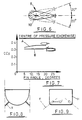
- Such fins will conveniently have a hydrodynamic cross-sectional profile and may resemble that shown in Figure 1 of the drawings, which shows a section of a fin 2 comprising a main body portion 4, provided with a movable trailing edge portion 6.
- the fin 2 is adapted to project from a ship's hull 8 as shown in Figure 2 and to be rotated as required about an axis 10 to vary the operating angle.
- the axis 10 is arranged transversely to a line extending lengthwise of the ship 8.
- edge portion 6 is hinged so as to be movable with respect to the body portion 4 by an angle greater than that of the rotation of the latter about axis 10.
- a fin housing 12 is provided in the hull to receive the fin 2 when in a retracted, non-operative position.
- a hydrofoil comprising a first, horizontal, hydrofoil arranged transversely beneath a craft and supported on the full thereof by two hydrofoil struts.
- the hydrofoils have a fish-shaped cross-section intended to be of benefit in the ventilation of the negative pressure area behind the "fish-tail". Full ventilation is achieved by inducing air flow along a trailing edge.
- French Patent specification No. 2214633 discloses a ship's rudder having an elongated cross-section having a middle parallel sided section between a front streamlined section and a tail portion.
- the rudder is arranged to pivot about a vertical axis at a point immediately forward of the parallel-sided section.
- the present invention provides a hydrodynamic stabilising fin for use in a submerged condition on water-borne craft, said fin member comprising a single one-piece member having an elongate body portion having a generally streamlined cross-section including a tapering portion reducing in a direction from a leading to a trailing zone thereof, and a ridge-like portion having an at least substantially wedge-shaped cross-section and being provided at a location rearward of said tapering portion, said wedge-shaped cross-section diverging in said direction and terminating in an end wall, mounting means being provided to mount the member so as to project in use from a hull of said craft.
- the end wall may lie at least substantially in a plane transverse to said direction.
- the profile of said end wall may be planar, or may be concave or include an obtuse or acute angle if desired.
- the fin member may be mounted with respect to a hull for rotation about an axis substantially transverse to a line extending fore-and-aft of said hull, said rotation providing a continuously variable operating angle in a predetermined range.
- the angle range may be ⁇ 20° with respect to zero deflection.
- the fin member may project from the hull in a horizontal or downwardly inclined attitude, at an angle preferably between 0° and 30°.
- diverging surfaces of said ridge-like member are arranged to include an angle between 20° and 90°, in one example the angle being 70°.
- the maximum, heightwise, thickness of the fin may be between 12% and 33% of the overall, fore-and-aft, width of the fin and preferably may be between 21% and 33% of said width, for example 26%.
- the maximum height of the end wall of the ridge-like section may be between 30% and 70% of the thickness of the fin, and preferably may be 50%.
- provision may be made for retracting the fins into an out-of-the-way condition as required, either by being withdrawn into a housing or by being pivoted either foreword or aft to be received in a stowing recess.
- a fin according to the invention may be provided with a tip plate or fence at the outboard end thereof for purposes which will be explained.
- Figure 4 shows a fin F according to the invention, having a hydrodynamically efficient profile comprising a smoothly rounded leading edge zone 14, an upper surface 16 and a lower surface 18 which converge in a direction towards a trailing zone 20.
- two diverging surfaces 22 and 24 define a ridge-like member 26 having a wedge-shaped cross-section.
- An end wall 28 lies in a plane transverse and substantially perpendicular to a line 30 extending fore-and-aft of the fin (see Figure 10).
- the fin is adapted to be pivotally adjusted about a transverse axis 32 in a manner similar to the adjustment about axis 10 of the fin of the prior art.
- Figure 5 shows a similar fin to that of Figure 4 with the addition of a plate 34 of the kind commonly known as a tip fence.
- a plate 34 of the kind commonly known as a tip fence.
- Such plates are known to increase the slope of the lift curve for a given operating angle. Thus the required angle may be reduced if a tip fence is present.
- a tip fence assists in increasing maximum lift by suppressing fin tip flow losses.
- Figure 6 illustrates the adjustment of the operating angle of the fin about the axis 32 with a 20° angle of adjustment both above and below a position of zero deflection shown in full lines.
- the centre of pressure for the fin section is located approximately at the zone of maximum thickness t (see Figure 10).
- Figure 7 shows the movement of the position of the centre of pressure for a range of angular deflections for the prior art fin shown in Figures 1 and 3 (curve A) and for the fin of Figure 5 (curve B).
- the upper curve A shows the amount of movement of the chordwise centre of pressure (CCp) over the range 5° - 20°
- the lower curve (B) illustrates that the centre of pressure of the fin according to the present invention shows virtually no change in the same range.
- the optimum shaft position (on axis 32) occurs at a zone where the largest diameter shaft can be accommodated. Because three is so little movement of the centre of pressure along the fore-and-aft chord line 30, with increasing fin angle, it will be appreciated that a relatively small torque is required to operate the fin over the preferred operating range.
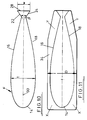
- Figures 10 and 11 illustrate more clearly a preferred profile or outline for the cross-section of a fin F according to the invention, Figure 11 shown also the provision of a plate 34.
- the value of t as 0.26 c has the advantage that a suitably large structure is available in which to mount a shaft 36 along the axis 32 to sustain the various levels of imposed loads.
- the value of w which is selected to be 50% of that of t gives a compromise between adequate lift and an acceptable level of drag.
- the value for ⁇ is selected bearing in mind that the more shallow the angle the less drag and lift.
- a value of 70° is given by way of the present example, a value as low as 20° may be used.
- the value of w is suitably increased by way of compensation.
- Figure 11 shows the preferred profile of the tip fence plate 34. Since the maximum areas of effective operation of the plate 34 are at the positions X and Y, the outline of the plate 34 has been chosen to reduce its height, dimension D, to a minimum. This facility has the practical advantage that the mouth opening of the hull recess can be reduced accordingly.
Landscapes
- Chemical & Material Sciences (AREA)
- Engineering & Computer Science (AREA)
- Combustion & Propulsion (AREA)
- Mechanical Engineering (AREA)
- Ocean & Marine Engineering (AREA)
- Bridges Or Land Bridges (AREA)
- Toys (AREA)
- Soil Working Implements (AREA)
- Structures Of Non-Positive Displacement Pumps (AREA)
- Hydraulic Turbines (AREA)
Abstract
Description
- The invention is concerned with improvements in or relating to a hydrodynamic stabilizing fin for water-borne craft.
- It is customary to provide ocean-going ships for example with anti-roll stabilizing means in the form of fins projecting outwardly from the ship's hull below the water-line to act to correct any tendency for the ship to roll with the movement of the water. Such fins will conveniently have a hydrodynamic cross-sectional profile and may resemble that shown in Figure 1 of the drawings, which shows a section of a
fin 2 comprising amain body portion 4, provided with a movabletrailing edge portion 6. Thefin 2 is adapted to project from a ship'shull 8 as shown in Figure 2 and to be rotated as required about anaxis 10 to vary the operating angle. Theaxis 10 is arranged transversely to a line extending lengthwise of theship 8. - In addition the
edge portion 6 is hinged so as to be movable with respect to thebody portion 4 by an angle greater than that of the rotation of the latter aboutaxis 10. Where necessary afin housing 12 is provided in the hull to receive thefin 2 when in a retracted, non-operative position. - It will be appreciated that the provision of the movable
trailing edge portion 6, while providing an acceptable level of performance, involves a very complex constructions and complicated control mechanisms. - It is an object of the invention to minimise the above disadvantages while obtaining a satisfactory level of performance in reducing roll.
- In U.S. Patent No. 5046444 there is described a hydrofoil comprising a first, horizontal, hydrofoil arranged transversely beneath a craft and supported on the full thereof by two hydrofoil struts. The hydrofoils have a fish-shaped cross-section intended to be of benefit in the ventilation of the negative pressure area behind the "fish-tail". Full ventilation is achieved by inducing air flow along a trailing edge.
- French Patent specification No. 2214633 discloses a ship's rudder having an elongated cross-section having a middle parallel sided section between a front streamlined section and a tail portion. The rudder is arranged to pivot about a vertical axis at a point immediately forward of the parallel-sided section.
- The present invention provides a hydrodynamic stabilising fin for use in a submerged condition on water-borne craft, said fin member comprising a single one-piece member having an elongate body portion having a generally streamlined cross-section including a tapering portion reducing in a direction from a leading to a trailing zone thereof, and a ridge-like portion having an at least substantially wedge-shaped cross-section and being provided at a location rearward of said tapering portion, said wedge-shaped cross-section diverging in said direction and terminating in an end wall, mounting means being provided to mount the member so as to project in use from a hull of said craft.
- Advantageously, the end wall may lie at least substantially in a plane transverse to said direction. Conveniently the profile of said end wall may be planar, or may be concave or include an obtuse or acute angle if desired.
- Preferably, the fin member may be mounted with respect to a hull for rotation about an axis substantially transverse to a line extending fore-and-aft of said hull, said rotation providing a continuously variable operating angle in a predetermined range. Advantageously, the angle range may be ±20° with respect to zero deflection.
- Conveniently the fin member may project from the hull in a horizontal or downwardly inclined attitude, at an angle preferably between 0° and 30°.
- Advantageously, diverging surfaces of said ridge-like member are arranged to include an angle between 20° and 90°, in one example the angle being 70°.
- Advantageously, the maximum, heightwise, thickness of the fin may be between 12% and 33% of the overall, fore-and-aft, width of the fin and preferably may be between 21% and 33% of said width, for example 26%.
- Advantageously, the maximum height of the end wall of the ridge-like section may be between 30% and 70% of the thickness of the fin, and preferably may be 50%.
- When installed in a ship's hull, provision may be made for retracting the fins into an out-of-the-way condition as required, either by being withdrawn into a housing or by being pivoted either foreword or aft to be received in a stowing recess.
- If desired, a fin according to the invention may be provided with a tip plate or fence at the outboard end thereof for purposes which will be explained.
- There will now be described, with reference to the relevant drawings, an example of a fin according to the invention. It will be understood that the description is given by way of example only and not by way of limitation.
- In the drawings:-
- Figures 1 to 3 illustrate a fin according to the prior art;
- Figure 4 is a perspective view of a fin according to the invention;
- Figure 5 is a perspective view of a fin according to the invention;
- Figure 6 illustrates three of the various angular positions available for the fin;
- Figure 7 is a graph comparing the position of the chordwise centres of pressure for the fins of Figure 1 (prior art) and of Figure 5 for a range of fin angle values;
- Figure 8 is a diagrammatic view of the position of permanently fixed fins with respect to a ship's hull;
- Figure 9 is a diagrammatic view of the position of retractable fins with respect to a ship's hull;
- Figure 10 is an outline representation of the cross-sectional profile of a fin as shown in Figure 4; and
- Figure 11 is an outline representative of the cross-sectional profile of a fin as shown in Figure 5.
- The prior art arrangement illustrated in Figures 1 to 3 has been described above.
- Figure 4 shows a fin F according to the invention, having a hydrodynamically efficient profile comprising a smoothly rounded leading
edge zone 14, anupper surface 16 and alower surface 18 which converge in a direction towards atrailing zone 20. Merging smoothly respectively with thesurfaces zone 20, twodiverging surfaces like member 26 having a wedge-shaped cross-section. Anend wall 28 lies in a plane transverse and substantially perpendicular to aline 30 extending fore-and-aft of the fin (see Figure 10). The fin is adapted to be pivotally adjusted about atransverse axis 32 in a manner similar to the adjustment aboutaxis 10 of the fin of the prior art. - Figure 5 shows a similar fin to that of Figure 4 with the addition of a
plate 34 of the kind commonly known as a tip fence. Such plates are known to increase the slope of the lift curve for a given operating angle. Thus the required angle may be reduced if a tip fence is present. - Moreover, the presence of a tip fence assists in increasing maximum lift by suppressing fin tip flow losses.
- Figure 6 illustrates the adjustment of the operating angle of the fin about the
axis 32 with a 20° angle of adjustment both above and below a position of zero deflection shown in full lines. The centre of pressure for the fin section is located approximately at the zone of maximum thickness t (see Figure 10). Figure 7 shows the movement of the position of the centre of pressure for a range of angular deflections for the prior art fin shown in Figures 1 and 3 (curve A) and for the fin of Figure 5 (curve B). The upper curve A shows the amount of movement of the chordwise centre of pressure (CCp) over therange 5° - 20° and the lower curve (B) illustrates that the centre of pressure of the fin according to the present invention shows virtually no change in the same range. - Thus, the optimum shaft position (on axis 32) occurs at a zone where the largest diameter shaft can be accommodated. Because three is so little movement of the centre of pressure along the fore-and-
aft chord line 30, with increasing fin angle, it will be appreciated that a relatively small torque is required to operate the fin over the preferred operating range. - While a fixed mounting arrangement which does not provide for retraction into a hull recess is suitable for hulls having a contour such as is shown in Figure 8, the configuration of hulls such as shown at H in Figure 9 requires a retraction facility. The fins F may be retracted in a forward or aft direction as preferred or may, as indicated in that Figure, be withdrawn inwardly into a recess 12'
- Figures 10 and 11 illustrate more clearly a preferred profile or outline for the cross-section of a fin F according to the invention, Figure 11 shown also the provision of a
plate 34. - The dimensions are identified as follows:-
- c =
- chord length (line 30)
- t =
- thickness of the fin F
- w =
- height of the
end wall 28 when in an operative orientation. - β =
- angle included by the
diverging surfaces like member 26. - In the example shown the values are, where c = 1 unit of length
- t =
- 0.26 c
- w =
- 0.13 c (i.e. 0.5t)
- β =
- 70°
- The value of t as 0.26 c has the advantage that a suitably large structure is available in which to mount a
shaft 36 along theaxis 32 to sustain the various levels of imposed loads. The value of w, which is selected to be 50% of that of t gives a compromise between adequate lift and an acceptable level of drag. The value for β is selected bearing in mind that the more shallow the angle the less drag and lift. Although a value of 70° is given by way of the present example, a value as low as 20° may be used. Preferably in such an instance, the value of w is suitably increased by way of compensation. - Figure 11 shows the preferred profile of the
tip fence plate 34. Since the maximum areas of effective operation of theplate 34 are at the positions X and Y, the outline of theplate 34 has been chosen to reduce its height, dimension D, to a minimum. This facility has the practical advantage that the mouth opening of the hull recess can be reduced accordingly. - Various modifications may be made within the scope of the invention.
Claims (6)
- A hydrodynamic stabilising fin for use in a submerged condition on water-borne craft, said fin comprising a single one-piece member having an elongate body portion (F) having a generally streamlined cross-section including a tapering portion reducing in a direction from a leading (14) to a trailing zone (20) thereof, and a ridge-like portion (26) having an at least substantially wedge-shaped cross-section and being provided at a location rearward of said tapering portion, said wedge-shaped cross-section diverging (22,24) in said direction and terminating in an end wall (28), mounting means (32,36) being provided to mount the member so as to project in use from a hull (8) of said craft.
- A fin as claimed in claim 1 wherein the end wall (28) lies at least substantially in a plane transverse to said direction.
- A fin as claimed in either one of claims 1 and 2, wherein the profile of the end wall (28) is planar or concave or includes an obtuse or acute angle.
- A fin as claimed in any one of the preceding claims, wherein said one-piece member is mounted on a shaft (36) with respect to said hull (8) for rotation about an axis (32) substantially transverse to a line extending fore-and-aft of said hull, said rotation providing a continuously variable operating angle in a predetermined range.
- A fin as claimed in claim 1, wherein diverging surfaces (22,24) of said ridge-like member (26) are arranged to include an angle between 20° and 90°.
- A fin as claimed in any one of the preceding claims, provided with a tip plate or fence (34) at the outboard end thereof.
Applications Claiming Priority (3)
| Application Number | Priority Date | Filing Date | Title |
|---|---|---|---|
| GB919100116A GB9100116D0 (en) | 1991-01-04 | 1991-01-04 | Hydrodynamic fin for water-borne craft |
| GB9100116 | 1991-01-28 | ||
| PCT/GB1991/002310 WO1992012046A1 (en) | 1991-01-04 | 1991-12-23 | Hydrodynamic fin for water-borne craft |
Publications (2)
| Publication Number | Publication Date |
|---|---|
| EP0571401A1 EP0571401A1 (en) | 1993-12-01 |
| EP0571401B1 true EP0571401B1 (en) | 1997-06-25 |
Family
ID=10687942
Family Applications (1)
| Application Number | Title | Priority Date | Filing Date |
|---|---|---|---|
| EP92902381A Expired - Lifetime EP0571401B1 (en) | 1991-01-04 | 1991-12-23 | Hydrodynamic fin for water-borne craft |
Country Status (5)
| Country | Link |
|---|---|
| EP (1) | EP0571401B1 (en) |
| JP (1) | JPH06506888A (en) |
| DE (2) | DE571401T1 (en) |
| GB (2) | GB9100116D0 (en) |
| WO (1) | WO1992012046A1 (en) |
Families Citing this family (5)
| Publication number | Priority date | Publication date | Assignee | Title |
|---|---|---|---|---|
| FR2728864B1 (en) * | 1994-12-29 | 1997-03-14 | Havre Chantiers | LEVELING EDGE STABILIZATION DEVICE FOR ANTI-ROLL SHIP STABILIZERS |
| FR2736888B1 (en) * | 1995-07-21 | 1997-09-26 | Havre Chantiers | ANTI-TANGAGE STABILIZATION DEVICE FOR VESSELS |
| FR2766004B1 (en) | 1997-07-11 | 1999-12-03 | Framatome Sa | GRID PADS FOR NUCLEAR FUEL ASSEMBLY AND GRID COMPRISING SUCH PADS |
| IT1311861B1 (en) | 1999-09-22 | 2002-03-19 | Fincantieri Cantieri Navali It | STABILIZER FIN STRUCTURE |
| CN102602510B (en) * | 2011-12-15 | 2015-07-22 | 深圳市海斯比船艇科技股份有限公司 | Collision and rolling resistant monohull ship |
Family Cites Families (4)
| Publication number | Priority date | Publication date | Assignee | Title |
|---|---|---|---|---|
| NO134459C (en) * | 1971-12-17 | 1976-10-13 | Nicolaus Kaufer | |
| NL174127C (en) * | 1973-01-24 | Werftunion Gmbh & Co | ONE PIECE, RECTANGULAR IN SIDE VIEW, RUDDERS WITH VERTICAL SIDEWALLS AND A SYMMETRIC PROFILE. | |
| DE3303424A1 (en) * | 1983-02-02 | 1984-08-09 | Werftunion Gmbh & Co, 4600 Dortmund | SYMMETRIC RUDDER PROFILES FOR MAXIMUM CROSS FORCES WITH SIMULTANEOUS MAXIMUM COURSE STABILITY |
| US5046444A (en) * | 1990-04-10 | 1991-09-10 | Michigan Wheel Corp. | Base vented subcavitating hydrofoil section |
-
1991
- 1991-01-04 GB GB919100116A patent/GB9100116D0/en active Pending
- 1991-12-23 EP EP92902381A patent/EP0571401B1/en not_active Expired - Lifetime
- 1991-12-23 WO PCT/GB1991/002310 patent/WO1992012046A1/en active IP Right Grant
- 1991-12-23 DE DE0571401T patent/DE571401T1/en active Pending
- 1991-12-23 JP JP4502542A patent/JPH06506888A/en active Pending
- 1991-12-23 DE DE69126669T patent/DE69126669T2/en not_active Expired - Fee Related
-
1993
- 1993-06-15 GB GB9312342A patent/GB2266073B/en not_active Expired - Fee Related
Also Published As
| Publication number | Publication date |
|---|---|
| JPH06506888A (en) | 1994-08-04 |
| DE571401T1 (en) | 1994-10-06 |
| EP0571401A1 (en) | 1993-12-01 |
| GB2266073B (en) | 1994-06-22 |
| GB9312342D0 (en) | 1993-08-18 |
| DE69126669D1 (en) | 1997-07-31 |
| WO1992012046A1 (en) | 1992-07-23 |
| DE69126669T2 (en) | 1998-01-08 |
| GB9100116D0 (en) | 1991-02-20 |
| GB2266073A (en) | 1993-10-20 |
Similar Documents
| Publication | Publication Date | Title |
|---|---|---|
| US8096255B2 (en) | Ship with stern equipped with a device for deflecting a flow of water | |
| US8881664B2 (en) | Method for maintaining the heading of a ship | |
| US5448963A (en) | Hydrofoil supported planing watercraft | |
| EP4017793B1 (en) | Hydrofoil system and marine vessel | |
| US5063869A (en) | Wing type sailing yacht | |
| US4280433A (en) | Underwater appendages for vessels | |
| US4615291A (en) | Hydrofoil boat | |
| US6805068B1 (en) | Hydrofoil system for lifting a boat partially out of water an amount sufficient to reduce drag | |
| KR101644506B1 (en) | Vessel provided with a foil below the waterline | |
| EP0571401B1 (en) | Hydrodynamic fin for water-borne craft | |
| US4959032A (en) | Water craft with guide fins | |
| US3424120A (en) | Hydrotunnel boat | |
| CA2472250C (en) | Wind driven sailing craft | |
| US7617793B2 (en) | Vessel provided with a foil situated below the waterline | |
| AU2003207004A1 (en) | Watercraft | |
| US4599964A (en) | Sailboat hull | |
| US5141456A (en) | Water craft with guide fins | |
| US6964240B1 (en) | Hull for high speed water craft | |
| US3804047A (en) | Retraction arrangement for the bow foil of hydrofoil craft | |
| US3611973A (en) | Rudder assembly | |
| US5263433A (en) | Hybrid hydrofoil strut leading edge extension | |
| EP1477402B1 (en) | Arrangement for controlling the motion of a vessel hull | |
| JPH06510498A (en) | Hydrofoil boat powered by wind power or auxiliary power | |
| GB2279620A (en) | Sailing vessel | |
| JP2002539018A (en) | Hull for planing and semi-planing boats |
Legal Events
| Date | Code | Title | Description |
|---|---|---|---|
| PUAI | Public reference made under article 153(3) epc to a published international application that has entered the european phase |
Free format text: ORIGINAL CODE: 0009012 |
|
| 17P | Request for examination filed |
Effective date: 19931007 |
|
| AK | Designated contracting states |
Kind code of ref document: A1 Designated state(s): DE FR IT |
|
| ITCL | It: translation for ep claims filed |
Representative=s name: STUDIO TORTA SOCIETA' SEMPLICE |
|
| EL | Fr: translation of claims filed | ||
| 17Q | First examination report despatched |
Effective date: 19940610 |
|
| DET | De: translation of patent claims | ||
| GRAG | Despatch of communication of intention to grant |
Free format text: ORIGINAL CODE: EPIDOS AGRA |
|
| GRAH | Despatch of communication of intention to grant a patent |
Free format text: ORIGINAL CODE: EPIDOS IGRA |
|
| GRAH | Despatch of communication of intention to grant a patent |
Free format text: ORIGINAL CODE: EPIDOS IGRA |
|
| GRAA | (expected) grant |
Free format text: ORIGINAL CODE: 0009210 |
|
| AK | Designated contracting states |
Kind code of ref document: B1 Designated state(s): DE FR IT |
|
| REF | Corresponds to: |
Ref document number: 69126669 Country of ref document: DE Date of ref document: 19970731 |
|
| ITF | It: translation for a ep patent filed | ||
| ET | Fr: translation filed | ||
| PLBE | No opposition filed within time limit |
Free format text: ORIGINAL CODE: 0009261 |
|
| STAA | Information on the status of an ep patent application or granted ep patent |
Free format text: STATUS: NO OPPOSITION FILED WITHIN TIME LIMIT |
|
| 26N | No opposition filed | ||
| PGFP | Annual fee paid to national office [announced via postgrant information from national office to epo] |
Ref country code: FR Payment date: 19991208 Year of fee payment: 9 |
|
| PGFP | Annual fee paid to national office [announced via postgrant information from national office to epo] |
Ref country code: DE Payment date: 19991230 Year of fee payment: 9 |
|
| PG25 | Lapsed in a contracting state [announced via postgrant information from national office to epo] |
Ref country code: FR Free format text: LAPSE BECAUSE OF NON-PAYMENT OF DUE FEES Effective date: 20010831 |
|
| REG | Reference to a national code |
Ref country code: FR Ref legal event code: ST |
|
| PG25 | Lapsed in a contracting state [announced via postgrant information from national office to epo] |
Ref country code: DE Free format text: LAPSE BECAUSE OF NON-PAYMENT OF DUE FEES Effective date: 20011002 |
|
| PG25 | Lapsed in a contracting state [announced via postgrant information from national office to epo] |
Ref country code: IT Free format text: LAPSE BECAUSE OF NON-PAYMENT OF DUE FEES;WARNING: LAPSES OF ITALIAN PATENTS WITH EFFECTIVE DATE BEFORE 2007 MAY HAVE OCCURRED AT ANY TIME BEFORE 2007. THE CORRECT EFFECTIVE DATE MAY BE DIFFERENT FROM THE ONE RECORDED. Effective date: 20051223 |