EP0570679B1 - Toner and method for manufacturing the same, and image forming apparatus using the toner - Google Patents
Toner and method for manufacturing the same, and image forming apparatus using the toner Download PDFInfo
- Publication number
- EP0570679B1 EP0570679B1 EP93104258A EP93104258A EP0570679B1 EP 0570679 B1 EP0570679 B1 EP 0570679B1 EP 93104258 A EP93104258 A EP 93104258A EP 93104258 A EP93104258 A EP 93104258A EP 0570679 B1 EP0570679 B1 EP 0570679B1
- Authority
- EP
- European Patent Office
- Prior art keywords
- particles
- toner
- particle
- average diameter
- volume average
- Prior art date
- Legal status (The legal status is an assumption and is not a legal conclusion. Google has not performed a legal analysis and makes no representation as to the accuracy of the status listed.)
- Expired - Lifetime
Links
Images

Classifications
-
- G—PHYSICS
- G03—PHOTOGRAPHY; CINEMATOGRAPHY; ANALOGOUS TECHNIQUES USING WAVES OTHER THAN OPTICAL WAVES; ELECTROGRAPHY; HOLOGRAPHY
- G03G—ELECTROGRAPHY; ELECTROPHOTOGRAPHY; MAGNETOGRAPHY
- G03G9/00—Developers
- G03G9/08—Developers with toner particles
- G03G9/0827—Developers with toner particles characterised by their shape, e.g. degree of sphericity
-
- G—PHYSICS
- G03—PHOTOGRAPHY; CINEMATOGRAPHY; ANALOGOUS TECHNIQUES USING WAVES OTHER THAN OPTICAL WAVES; ELECTROGRAPHY; HOLOGRAPHY
- G03G—ELECTROGRAPHY; ELECTROPHOTOGRAPHY; MAGNETOGRAPHY
- G03G9/00—Developers
- G03G9/08—Developers with toner particles
- G03G9/0825—Developers with toner particles characterised by their structure; characterised by non-homogenuous distribution of components
-
- G—PHYSICS
- G03—PHOTOGRAPHY; CINEMATOGRAPHY; ANALOGOUS TECHNIQUES USING WAVES OTHER THAN OPTICAL WAVES; ELECTROGRAPHY; HOLOGRAPHY
- G03G—ELECTROGRAPHY; ELECTROPHOTOGRAPHY; MAGNETOGRAPHY
- G03G9/00—Developers
- G03G9/08—Developers with toner particles
- G03G9/087—Binders for toner particles
- G03G9/08775—Natural macromolecular compounds or derivatives thereof
- G03G9/08782—Waxes
Definitions
- the present invention relates to an electrophotographic toner which is used to form an image out of a toner image contact-heated and fixed on paper by a heat roller in a dry type electrostatic copying process, a method for manufacturing the toner, and an image forming apparatus using the toner.
- a contact-heating fixing method has been widely used in a dry type electrostatic copying process.
- an electrostatic latent image is formed on a photoconductive layer on the surface of a drum-shaped photosensitive body, and developed by a toner to form a toner image.
- the toner image is contact-heated by a heat roller and fixed on paper or the like.
- the contact-heating fixing method has the advantage of high thermal efficiency and rapid fixing, it has the drawback in which an offset phenomenon appears and the paper is wound on the heat roller.
- the toners disclosed in the Japanese Publication are powders of adhesive resin containing a colorant and a charging control agent, and the wax is externally attached to the powders. Since, however, the wax is easily softened at high temperature and the softened wax has tackiness, if the toners are agitated at the time of development, wax particles are softened and attached to each other or to toner particles, resulting in cohesion of the toners. If the toners cohere with one another, the toner particles are increased and, even though the toners are charged by friction with carriers in two-component development, they cannot be sufficiently charged. For this reason, the toners peel off to contaminate the inside of a copying machine and a blur occurs to degrade image quality.
- the wax Since the surface energy of the toners disclosed in the above Japanese Publication is small, the wax is easy to separate from the surfaces of the toner particles when the toners are agitated in a developing unit. If the separated wax is charged and attached to a photosensitive drum, a black point appears on an image, thereby degrading image quality.
- the wax separated from the toner particles is attached to the photosensitive drum to form a film and thus to prevent a good image from being formed. It is thus necessary to remove the wax from the photosensitive drum by a cleaning roller. For this reason, the conventional method has a drawback in which the photosensitive drum is much worn to reduce its durability and thus to increase a workload of maintenance.
- An object of the present invention is to provide a toner which does not cohere with another toner and is capable of forming an image free from a blur or a black point, a method for manufacturing the toner, and an image forming apparatus using the toner.
- a toner comprising:
- a method for manufacturing a toner comprising the steps of:
- an image forming apparatus comprising:
- the toner of the present invention and the toner obtained by the toner manufacturing method of the present invention are used in an image forming apparatus, no cohesion of toners occurs; therefore, an image free from a blur or a black point can be formed.
- these toners as developers, a photosensitive drum can be prevented from being damaged, and a workload of the maintenance of the apparatus can be reduced.
- Fig. 1 shows a constitution of an electrophotographic copying machine of the present invention.
- a drum-shaped photosensitive body 103 serving as an image bearing body is provided substantially in the central part of a body 101 of the copying machine, and can be rotated in the direction of arrow a .
- the following devices and units are fixedly arranged around the photosensitive body 103.
- a charger 105 is arranged to uniformly charge the surface of the photosensitive body 103, and a slit glass 107 for slit-exposing a document image onto the charged photosensitive body 103 as an optical image is arranged above the photosensitive body 103 and on the downstream side of the charger 105 in the rotating direction of the body 103.
- a developing unit 109 for developing an electrostatic latent image on the photosensitive body 103 by attaching a toner to the latent image, is arranged on the downstream side of the slit glass 107 in the rotating direction of the body 103.
- the developing unit 109 contains toners 110 mixed with carriers of magnetic substances as developers. The toners will be described in detail later.
- the developing unit 109 includes an agitation roller 201 for agitating the developers by its rotation to triboelectrically charge them, and a supply roller 202 for supplying the developers agitated by the agitation roller 201 to a magnet roller 203.
- the developing unit 109 also includes a magnet roller 203 on which the north and south poles are arranged alternately in its rotating direction, and the magnet roller 203 is close to the photosensitive body 103 and can be rotated in the direction of arrow 1.
- a transfer unit 111 and a separation unit 113 are arranged on the downstream side of the developing unit 109 in the rotating direction of the body 103.
- the transfer unit 111 transfers a toner image formed by the developing unit 109 to copying paper (hereinafter referred to as paper), and the separation unit 113 separates the paper from the surface of the photosensitive body 103.
- An elimination unit 117 for lowering the potential of the photosensitive body 103 is fixed between the cleaning unit 115 and the charger 105.
- the body 101 includes a document glass 119 on which a document is placed, and an optical system 121 for irradiating the document on the document glass 119 and guiding light reflected by the document to the surface of the photosensitive body 103.
- the optical system 121 has a lamp 123 serving as a light source, mirrors 124, 125, 127, 129, 131 and 133 for reflecting light emitted from the light source, and a lens unit 135 for forming an image from the reflected light.
- the lamp 123 and mirror 124 are arranged movably under the document glass 119, and the mirrors 125 and 127 are so constituted as to move at half of the speed of the lamp 123 in order to keep an optical path length constant.
- the light reflected by the mirror 133 penetrates the slit glass 107 and is guided to the surface of the photosensitive body 103.
- a manual paper feeding tray 141 for storing paper is detachably provided in the middle portion on one side of the body 101, and a pickup roller 143 for picking up the paper stored in the tray 141 is provided above the end of the tray 141.
- a paper discharging tray 171 for discharging the paper on which a copy image is formed is mounted on the other side of the body 101.
- a carrying path 142 for carrying the paper is formed between the manual paper feeding tray 141 and the paper discharging tray 171.
- the carrying path 142 is represented by a dotted line in Fig. 1.
- First and second pairs of rollers are attached to the body 101 in the upstream portion of the carrying path 142.
- the first pair of rollers is adjacent to the manual paper feeding tray 141 and includes a paper feeding roller 145 and a separation roller 147.
- the paper feeding roller 145 can be rotated in the direction of arrow b in Fig. 1 and is used to send the paper picked up by the pickup roller 143 to the second pair of rollers by its rotation.
- the separation roller 147 is arranged under and in contact with the paper feeding roller 145. When two or more sheets of paper are supplied from the pickup roller 143, the separation roller 147 is rotated in a direction opposite to that of the paper feeding roller 145 to return the extra paper to the manual paper feeding tray 141.
- the second pair of rollers is a resist roller 149 with an upper roller and a lower roller.
- the resist roller 149 aligns the paper sent from the paper feeding roller 145 when it touches the leading edge of the paper and then supplies the paper so that a toner image is put on the paper between the photosensitive body 103 and the transfer unit 111.
- the transfer unit 111 and the separation 113 are arranged in substantially the middle of the carrying path 142, and a conveyer belt 151 for conveying the paper is arranged ahead of the separation unit 113.
- a fixing unit 153 for fixing the toners 110 on the paper by heating and pressing is arranged in the downstream portion of the carrying path 142.
- the fixing unit 153 has a heat roller 157 and a pressing roller 159 which can be rotated in the directions of arrows c and d .
- the heat roller 157 includes a heat lamp 155 serving as a heater and contacts the pressing roller 159.
- the surface of the heat roller 157 is formed by metal of good thermal conductivity, and the surface of the pressing roller 159 is formed by elastic rubber so that the roller 159 is easy to contact the roller 157.
- a paper discharging roller 161 for discharging the paper on which a copy image is formed, to the paper discharging tray 171, is provided in the downstream portion of the carrying path 142.
- the above-described copying machine operates in the following copying process.
- the surface of the photosensitive body 103 is uniformly charged by corona discharge of the charger 105.
- the lamp 123 of the optical system 121 scans the document glass 119 from below to emit light to a document on the glass 119.
- the light emitted from the lamp 123 is reflected, and the reflected light is guided to the lens unit 135.
- the reflected light is reversed, and guided to the charged photosensitive body 103 through the slit glass 107. If the photosensitive body 103 is exposed by the reflected light, charges are lost from the surface of the photosensitive body 103, thereby forming an electrostatic latent image.
- the toners 110 and carriers charged triboelectrically by the agitation roller 201 are supplied to the magnet roller 203 by means of the supply roller 202.
- the toners 110 and carriers form a magnetic brush on the magnet roller 203 by lines of magnetic force formed between the north and south poles of the magnet roller 203.
- the carriers are always attracted to the magnet roller 203 by magnetism, and the toners 110 and carriers are electrically attracted to each other.
- the magnet roller 203 and the photosensitive body 103 are rotated and, when the magnetic brush and the electrostatic latent image on the photosensitive body 103 come closer to each other, the toners 110 are separated from the carriers by stronger electrostatic attraction of the electrostatic latent image and then attached to the image.
- the toners 110 attached to the electrostatic latent image form a toner image.
- unnecessary toners 110 are prevented from attaching to the photosensitive body 103 by applying a developing bias to the magnet roller 203 and the photosensitive 103 by a voltage generator (not shown).
- Paper sheets are picked from the paper feeding tray 141 by the pickup roller 143, and one of the paper sheets is conveyed to the resist roller 149 by rotation of the paper feeding roller 145 and the separation roller 147.
- the resist roller 149 aligns the leading edge of the paper sheet, and send it between the photosensitive body 103 and the transfer unit 111, thereby placing the electrostatic latent image of the photosensitive body 103 on the paper sheet.
- the toner image is transferred to the reverse side of the sheet by the function of the transfer unit 111.
- the sheet on which the toner image is formed is separated from the surface of the photosensitive body 103 by the separation unit 113, and conveyed to the fixing unit 153 via the conveyer belt 151.
- the heat roller 157 which is heated by the heat lamp 155, and the pressing roller 159 are partially pressed against each other and rotated in their respective directions. During the rotation of these rollers, the paper sheet is caused to pass a portion where the two rollers are pressed so that the toner image faces the heat roller 157, thereby fixing the toner image on the sheet.
- the toners 110 are fused by heat of the heat roller 157, the conductive efficiency of heat is enhanced by pressure of the pressing roller 159, and the toners soak into fibers of the paper sheet.
- the paper on which the copy image is formed in the foregoing process is discharged to the paper discharging tray 171 via the paper discharge roller 161.
- styrene acrylic resin (Mitsui Toatsu Chemical, Inc.) is prepared as binding resin
- 8 parts by weight of carbon black (MA-100: Mitsubishi Chemical Industries Ltd.) is prepared as a colorant
- 1 part by weight of triphenylmethane derivative (copy blue PR: Hoechst) and 1 part by weight of quaternary ammonium salt (P-51: Orient Chemical) are prepared as charging control agents.
- these materials are uniformly mixed and then kneaded by a kneader for thirty minutes at a temperature of 140°C. They are cooled and then milled by a hammer mill to obtain first particles whose average diameter is 110 ⁇ m.
- second particles e.g., wax
- low-molecular-weight polypropylene VISCOL 550P: Sanyo Chemical Industries, Ltd.
- I-type mill Nippon Pneumatic
- wax particles whose average diameter is 0.8 ⁇ m.
- titanium oxide particle serving as a third particle Tian Kogyo K.K.
- average diameter 0.07 ⁇ m
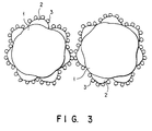
- the second particles externally attached to the surfaces of the first particles which are constituted by thermoplastic binding resin and colorant, do not contact each other, as shown in Fig. 3.
- the third particles are externally attached to the second particles. Since the second particles are mechanically hit against the first particles, they are crushed and attached to the first particles. When the toner particles serving as the first particles come closer to each other, the wax particles serving as the second particles do not contact each other, with the result that no cohesion of the toner particles occur.
- the amount of mixture of the second particles, that is, the low-molecular-weight polypropylene to which titanium oxide is attached, with the first particles is changed from 1 part by weight to 0.08 by weight, thereby forming toners.
- a developer was prepared from these toners to make a copy, with the result that the toners had a good offset-resistant property, and no cohesion of the toners occurred or no black points were generated.
- the amount of mixture of the second particles with the first particles is changed from 1 part by weight to 10 parts by weight, thereby forming toners.
- a developer was prepared from these toners to make a copy, with the result that the toners had a good offset-resistant property, and no cohesion of the toners occurred or no black points were generated.
- Hardening castor oil (Castor Wax Nippon Oil and Fats Co., Ltd.) is used for wax for preventing an offset phenomenon of the embodiment 1, thereby obtaining toners.
- a developer was prepared from these toners and evaluated.
- the obtained toners had a good offset-resistant property, and no cohesion of the toners occurred or no black points were generated, as in the case of the low-molecular-weight polypropylene.
- Polyethylene High Wax 200P: Mitsui Petrochemical Industries, Ltd.
- a developer was prepared from these toners and evaluated, with the result that the toners had a good offset-resistant property, and no cohesion of the toners occurred or no black points were generated.
- the subsequent operations were the same as those of the embodiment 1.
- the toners of the embodiment 6 were evaluated and thus produced the same effects as those of the embodiment 1.
- 0.2 part by weight of silica (R972: Aerogel) was mixed with the particles to form toners.
- a developer was prepared from the toners and then evaluated. As a result, an offset phenomenon appeared at a temperature of 210°C of the fixing unit, and a black point occurred when the number of copies reached 8000.
- the wax used in the above embodiments can be replaced with a normal series and isoparaffin which are natural products or each have 15 or more carbon atoms, a compound of the normal series and isoparaffin having an unsaturated group, chlorides of the normal series and isoparaffin, fatty acid having 15 or more carbon atoms, alcohol and ester of the fatty acid, chlorides of the alcohol and ester, fatty acid metal salt having 15 or more carbon atoms, a fatty acid amido class having a hydrocarbon chain whose carbon atoms is 15 or more, a bis fatty acid amido class, a low-molecular polyolefin compound, a silicone compound, a fluorine compound, and the like.
- the nonmagnetic particles of the third particles attached to the surface of the wax of the second particles can be replaced with silica, alumina, titanium oxide, barium titanate, magnesium titanate, calcium titanate, strontium titanate, zinc oxide, chromium oxide, ceric oxide, antimony oxide, zirconium oxide, silicon carbide, or the like.
- the titanium oxide and alumina are particularly suitable for the nonmagnetic particles since they hardly have a polarity and are almost neutral, and thus affect neither the charging characteristic of toners nor the carriers used in the two-component development.
- the nonmagnetic particles are able to cover about 50 to 100% of the surface of the wax, and the wax is able to cover about 50 to 100% of the surface of the first particle. If extra nonmagnetic particles are attached to the surface of the wax, a photosensitive drum is damaged. If the nonmagnetic particles run short, it is impossible to prevent wax from being adhered to another wax. If extra wax is attached to the surface of the first particle, cohesion of toners occurs and black points are generated. If the wax runs short, an offset phenomenon cannot be prevented.
- Styrene such as polystyrene, poly-p-chlorostyrene, polyvinyltoluene, styrene-p-chlorostyrene copolymer, and styrene-vinyltoluene copolymer; a homopolymer of a substitute for the styrene; a copolymer of the styrene and the homopolymer; a copolymer of styrene such as styrene-methyl acrylate copolymer, styrene-ethyl acrylate copolymer, and styrene-n-butyl acrylate copolymer and acrylate; a copolymer of styrene such as styrene-methyl methacrylate copolymer, styrene-ethyl methacrylate copolymer, and styrene-n-buty
- a styrene-series copolymer of styrene such as styrene-acrylonitrile copolymer, styrene-vinyl methyl ether copolymer, styrene-butadiene copolymer, styrene-vinyl methyl ketone copolymer, styrene-acrylonitrile indene copolymer, and styrene-ester maleate copolymer and vinyl-system monomer, polymethylmethacrylate, polybutylmethacrylate, polyvinyl acetate, polyester, polyamide; epoxy resin, polyvinyl butyral, polyacrylic acid, phenolic resin, aliphatic or alicyclic, hydrocarbon resin, petroleum resin, chlorinated paraffin, and the like can also be used as the binding resin either alone or in combination.
- one or at least two of all charging control agents of the negative-electrode control agents such as alkyl salicylic acid metal chelate, chlorinated polyester, polyester having extra acid radicals, chlorinated polyolefin, metal acid of fatty acid, and soap of resin acid, and positive-electrode control agents such as dimethylaminoethylmethacrylate-styrene copolymer, fluorine activated agent, hydrophobic silica, and quaternary ammonium salt, can be used as the charging control agent.
- the negative-electrode control agents such as alkyl salicylic acid metal chelate, chlorinated polyester, polyester having extra acid radicals, chlorinated polyolefin, metal acid of fatty acid, and soap of resin acid
- positive-electrode control agents such as dimethylaminoethylmethacrylate-styrene copolymer, fluorine activated agent, hydrophobic silica, and quaternary ammonium salt
- the toners of the above embodiments are used as two-component developers, however, they can be used as monocomponent developers.
- Glass beads, iron powder, ferrite, magnetic particles, and the like can be used as the carriers. It is preferable to use a mixer capable of high mechanical pressure, such as a hybridizer and a mechanofusion in the process of manufacturing toners.
Description
Claims (5)
- Electrophotographic toner comprising:first particles (1) including thermoplastic binding resin and a colorant mixed into the thermoplastic binding resin to apply a predetermined color thereto, and having a first volume average diameter Rt which falls in the range of 5 µm ≦ Rt ≦ 20 µm;second particles (2) attached to a surface of said first particle and constituted of a wax to improve a separation property of said first particle, and having a second volume average diameter Rw which falls in the range of 0.4 µm ≤ Rw ≤ 1.6 µm ; andthird third particles (3) attached to a surface of said second particle to prevent said second particle from directly contacting another second particle, and having a third volume average diameter Ri which falls in the range of 0.032 µm ≤ Ri ≦ 0.128 µm, wherein the third particles (3) are constituted of silica, alumina, titanium oxide, barium titanate, magnesium titanate, calcium titanate, strontium titanate, zinc oxide, chromium oxide, ceric oxide, antimony oxide, zirconium oxide, silicon carbide.
- Toner according to claim 1, characterized in that said third particles (3) has an electrically neutral substance.
- Toner according to claim 1, characterized in that said third particles (3) has a nonmagnetic substance.
- Method for manufacturing an electrophotographic toner, comprising the steps of:mixing thermoplastic binding resin and a colorant for applying a predetermined color to the thermoplastic binding resin to form first particles (1) having a first volume average diameter Rt with 5 µm ≦ Rt ≦ 20 µm;mixing second particles (2) constituted of a wax having a second volume average diameter Rw with 0.4 µm ≦ Rw ≦ 1.6 µm, with third particles (3) having a third volume average diameter Ri with 0.032 µm ≦ Ri ≦ 0.128 µm and attaching the third particles to a surface of said second particles to prevent said second particles from directly contacting another second particles wherein the third particles (3) are constituted of silica, alumina, titanium oxide, barium titanate, magnesium titanate, calcium titanate, strontium titanate, zinc oxide, chromium oxide, ceric oxide, antimony oxide, zirconium oxide, silicon carbide; andattaching said second particles to a surface of said first particles to improve a separation property of said first particles.
- Electrophotographic image forming apparatus comprising:exposure means (121) for exposing an image bearing body to form an electrostatic latent image;development means (109) for developing the electrostatic latent image using a toner, said toner comprising first particles having a first volume average diameter Rt with 5 µm ≦ Rt ≦ 20 µm and including thermoplastic binding resin and a colorant mixed into the thermoplastic binding resin to apply a predetermined color thereto, second particles attached to a surface of said first particles and constituted of wax to improve a separation property of said first particle, and having a second volume average diameter Rw with 0.4 µm ≦ Rw ≦ 1.6 µm, and third particles attached to a surface of said second particles to prevent said second particle from directly contacting another second particles, and having a third volume average diameter Ri with 0.032 µm ≦ Ri ≦ 0.128 µm;transfer means (111) for transferring a toner image formed by said development means to a medium on which an image is to be formed; andfixing means (153) for heating and fixing the toner image on the medium.
Applications Claiming Priority (2)
| Application Number | Priority Date | Filing Date | Title |
|---|---|---|---|
| JP128354/92 | 1992-05-21 | ||
| JP4128354A JPH05323654A (en) | 1992-05-21 | 1992-05-21 | Toner, production of toner and image forming device |
Publications (2)
| Publication Number | Publication Date |
|---|---|
| EP0570679A1 EP0570679A1 (en) | 1993-11-24 |
| EP0570679B1 true EP0570679B1 (en) | 1998-02-04 |
Family
ID=14982750
Family Applications (1)
| Application Number | Title | Priority Date | Filing Date |
|---|---|---|---|
| EP93104258A Expired - Lifetime EP0570679B1 (en) | 1992-05-21 | 1993-03-16 | Toner and method for manufacturing the same, and image forming apparatus using the toner |
Country Status (4)
| Country | Link |
|---|---|
| US (1) | US5320926A (en) |
| EP (1) | EP0570679B1 (en) |
| JP (1) | JPH05323654A (en) |
| DE (1) | DE69316787T2 (en) |
Families Citing this family (10)
| Publication number | Priority date | Publication date | Assignee | Title |
|---|---|---|---|---|
| JP3156881B2 (en) * | 1992-10-19 | 2001-04-16 | 株式会社リコー | Electrostatic toner |
| US5424162A (en) * | 1992-11-24 | 1995-06-13 | Minolta Camera Kabushiki Kaisha | Toner for electrophotography containing wax-particles dispersed in binder resin |
| JP3314326B2 (en) * | 1995-05-30 | 2002-08-12 | ミノルタ株式会社 | Toner for developing electrostatic latent images |
| US5912100A (en) * | 1996-01-31 | 1999-06-15 | Ricoh Company, Ltd. | Toner for developing electrostatic images |
| JP3604267B2 (en) * | 1997-12-24 | 2004-12-22 | 株式会社リコー | Electrophotographic toner |
| JP2004163879A (en) * | 2002-06-13 | 2004-06-10 | Heidelberger Druckmas Ag | Electrophotographic toner in which wax is uniformly dispersed |
| JP3987065B2 (en) * | 2004-10-19 | 2007-10-03 | シャープ株式会社 | Two-component developer and image forming method |
| US8064796B2 (en) * | 2006-03-30 | 2011-11-22 | Mitsubishi Chemical Corporation | Image forming apparatus |
| JP5609198B2 (en) * | 2010-03-24 | 2014-10-22 | 富士ゼロックス株式会社 | Electrostatic image developing toner, electrostatic image developer, toner cartridge, process cartridge, image forming apparatus, and image forming method |
| JP5629668B2 (en) * | 2011-10-11 | 2014-11-26 | 京セラドキュメントソリューションズ株式会社 | Positively chargeable toner |
Family Cites Families (16)
| Publication number | Priority date | Publication date | Assignee | Title |
|---|---|---|---|---|
| JPS4999034A (en) * | 1973-01-26 | 1974-09-19 | ||
| US4051077A (en) * | 1974-02-25 | 1977-09-27 | Xerox Corporation | Non-filming dual additive developer |
| JPS5219535A (en) * | 1975-08-06 | 1977-02-14 | Ricoh Co Ltd | Dry type developing powder |
| JPS57136659A (en) * | 1981-02-18 | 1982-08-23 | Hitachi Metals Ltd | Toner grain for electrostatic charge latent image development |
| JPS63163375A (en) * | 1986-12-25 | 1988-07-06 | Ricoh Co Ltd | Dry type heat fixable toner |
| JP2568195B2 (en) * | 1987-03-27 | 1996-12-25 | 東洋インキ製造株式会社 | Powder toner |
| JPH07120069B2 (en) * | 1987-05-30 | 1995-12-20 | 三田工業株式会社 | Method for manufacturing heat fixing toner |
| JPS6462666A (en) * | 1987-09-02 | 1989-03-09 | Soken Kagaku Kk | Toner and production thereof |
| JP2702142B2 (en) * | 1988-04-07 | 1998-01-21 | 松本油脂製薬株式会社 | toner |
| JPH01302269A (en) * | 1988-05-30 | 1989-12-06 | Dainippon Ink & Chem Inc | Method for manufacturing electrostatic charge image developing toner |
| JPH01309075A (en) * | 1988-06-08 | 1989-12-13 | Sharp Corp | Electrophotographic toner |
| JP2502353B2 (en) * | 1988-11-22 | 1996-05-29 | キヤノン株式会社 | Developer for reversal development |
| JPH03125156A (en) * | 1989-10-11 | 1991-05-28 | Toshiba Corp | Toner for electrophotograhy |
| JPH0450859A (en) * | 1990-06-15 | 1992-02-19 | Konica Corp | Electrostatic image developing toner |
| US5124222A (en) * | 1990-09-27 | 1992-06-23 | Nashua Corporation | Toner and developer compositions having cleaning and lubricating additives |
| JP3042023B2 (en) * | 1991-05-10 | 2000-05-15 | ミノルタ株式会社 | Electrostatic image developer |
-
1992
- 1992-05-21 JP JP4128354A patent/JPH05323654A/en active Pending
-
1993
- 1993-03-12 US US08/031,192 patent/US5320926A/en not_active Expired - Lifetime
- 1993-03-16 EP EP93104258A patent/EP0570679B1/en not_active Expired - Lifetime
- 1993-03-16 DE DE69316787T patent/DE69316787T2/en not_active Expired - Fee Related
Also Published As
| Publication number | Publication date |
|---|---|
| US5320926A (en) | 1994-06-14 |
| DE69316787T2 (en) | 1998-09-10 |
| DE69316787D1 (en) | 1998-03-12 |
| JPH05323654A (en) | 1993-12-07 |
| EP0570679A1 (en) | 1993-11-24 |
Similar Documents
| Publication | Publication Date | Title |
|---|---|---|
| JP2001147570A (en) | Color image forming method | |
| EP0570679B1 (en) | Toner and method for manufacturing the same, and image forming apparatus using the toner | |
| JP2632237B2 (en) | Non-magnetic one-component development method | |
| EP0614129B1 (en) | Magnetic carrier, developer comprising the carrier for developing latent electrostatic images, electrographic photoconductor, and image formation method using the same | |
| JP3854361B2 (en) | Toner for developing electrostatic image and image forming method using the same | |
| EP0617339B1 (en) | Granular charging agent and charging method and image forming method using the same | |
| KR20020077111A (en) | Toner for non-magnetic monocomponent development | |
| US5266437A (en) | Electrophotographic imaging forming method veins using toner containing complex fine particles | |
| JPS6356543B2 (en) | ||
| JPH11212299A (en) | Image forming method | |
| JP3930944B2 (en) | Image forming method | |
| EP0257364A1 (en) | Developing method for electrostatic latent image | |
| JP3410183B2 (en) | Image forming method | |
| JP2607398B2 (en) | Non-magnetic one-component development method | |
| JPH117197A (en) | Method for image forming and negative charged type non-magnetic toner | |
| JPH05289411A (en) | Negatively charged toner and image forming device | |
| JP3164717B2 (en) | Image forming device | |
| JPH0227363A (en) | Toner for electrophotography | |
| JPS6283767A (en) | Two color-image forming method | |
| JPH0812443B2 (en) | Electrostatic image developing method and apparatus | |
| JPH0458027B2 (en) | ||
| JPS6073546A (en) | Dry developer | |
| JPH07175274A (en) | Image forming method | |
| JP2002287419A (en) | Magnetic monocomponent developer | |
| JPH10198076A (en) | Carrier for developing electrostatic latent image, electrostatic latent image developer using same and image forming method |
Legal Events
| Date | Code | Title | Description |
|---|---|---|---|
| PUAI | Public reference made under article 153(3) epc to a published international application that has entered the european phase |
Free format text: ORIGINAL CODE: 0009012 |
|
| 17P | Request for examination filed |
Effective date: 19930413 |
|
| AK | Designated contracting states |
Kind code of ref document: A1 Designated state(s): DE FR GB |
|
| 17Q | First examination report despatched |
Effective date: 19960131 |
|
| GRAG | Despatch of communication of intention to grant |
Free format text: ORIGINAL CODE: EPIDOS AGRA |
|
| GRAG | Despatch of communication of intention to grant |
Free format text: ORIGINAL CODE: EPIDOS AGRA |
|
| GRAH | Despatch of communication of intention to grant a patent |
Free format text: ORIGINAL CODE: EPIDOS IGRA |
|
| GRAG | Despatch of communication of intention to grant |
Free format text: ORIGINAL CODE: EPIDOS AGRA |
|
| GRAH | Despatch of communication of intention to grant a patent |
Free format text: ORIGINAL CODE: EPIDOS IGRA |
|
| GRAH | Despatch of communication of intention to grant a patent |
Free format text: ORIGINAL CODE: EPIDOS IGRA |
|
| GRAA | (expected) grant |
Free format text: ORIGINAL CODE: 0009210 |
|
| AK | Designated contracting states |
Kind code of ref document: B1 Designated state(s): DE FR GB |
|
| REF | Corresponds to: |
Ref document number: 69316787 Country of ref document: DE Date of ref document: 19980312 |
|
| ET | Fr: translation filed | ||
| REG | Reference to a national code |
Ref country code: GB Ref legal event code: 746 Effective date: 19981008 |
|
| PLBE | No opposition filed within time limit |
Free format text: ORIGINAL CODE: 0009261 |
|
| STAA | Information on the status of an ep patent application or granted ep patent |
Free format text: STATUS: NO OPPOSITION FILED WITHIN TIME LIMIT |
|
| 26N | No opposition filed | ||
| PGFP | Annual fee paid to national office [announced via postgrant information from national office to epo] |
Ref country code: FR Payment date: 19990309 Year of fee payment: 7 |
|
| REG | Reference to a national code |
Ref country code: FR Ref legal event code: D6 |
|
| PGFP | Annual fee paid to national office [announced via postgrant information from national office to epo] |
Ref country code: GB Payment date: 19990318 Year of fee payment: 7 |
|
| PGFP | Annual fee paid to national office [announced via postgrant information from national office to epo] |
Ref country code: DE Payment date: 19990319 Year of fee payment: 7 |
|
| PG25 | Lapsed in a contracting state [announced via postgrant information from national office to epo] |
Ref country code: GB Free format text: LAPSE BECAUSE OF NON-PAYMENT OF DUE FEES Effective date: 20000316 |
|
| GBPC | Gb: european patent ceased through non-payment of renewal fee |
Effective date: 20000316 |
|
| PG25 | Lapsed in a contracting state [announced via postgrant information from national office to epo] |
Ref country code: FR Free format text: LAPSE BECAUSE OF NON-PAYMENT OF DUE FEES Effective date: 20001130 |
|
| REG | Reference to a national code |
Ref country code: FR Ref legal event code: ST |
|
| PG25 | Lapsed in a contracting state [announced via postgrant information from national office to epo] |
Ref country code: DE Free format text: LAPSE BECAUSE OF NON-PAYMENT OF DUE FEES Effective date: 20010103 |