EP0570310A1 - Signal generator for the remote detection of functional failure of overvoltage protection devices mounted on electrical distribution lines - Google Patents
Signal generator for the remote detection of functional failure of overvoltage protection devices mounted on electrical distribution lines Download PDFInfo
- Publication number
- EP0570310A1 EP0570310A1 EP93420194A EP93420194A EP0570310A1 EP 0570310 A1 EP0570310 A1 EP 0570310A1 EP 93420194 A EP93420194 A EP 93420194A EP 93420194 A EP93420194 A EP 93420194A EP 0570310 A1 EP0570310 A1 EP 0570310A1
- Authority
- EP
- European Patent Office
- Prior art keywords
- capacitor
- generator according
- line
- frequency
- arrester
- Prior art date
- Legal status (The legal status is an assumption and is not a legal conclusion. Google has not performed a legal analysis and makes no representation as to the accuracy of the status listed.)
- Withdrawn
Links
Images


Classifications
-
- H—ELECTRICITY
- H02—GENERATION; CONVERSION OR DISTRIBUTION OF ELECTRIC POWER
- H02H—EMERGENCY PROTECTIVE CIRCUIT ARRANGEMENTS
- H02H3/00—Emergency protective circuit arrangements for automatic disconnection directly responsive to an undesired change from normal electric working condition with or without subsequent reconnection ; integrated protection
- H02H3/02—Details
- H02H3/04—Details with warning or supervision in addition to disconnection, e.g. for indicating that protective apparatus has functioned
- H02H3/042—Details with warning or supervision in addition to disconnection, e.g. for indicating that protective apparatus has functioned combined with means for locating the fault
-
- H—ELECTRICITY
- H02—GENERATION; CONVERSION OR DISTRIBUTION OF ELECTRIC POWER
- H02H—EMERGENCY PROTECTIVE CIRCUIT ARRANGEMENTS
- H02H1/00—Details of emergency protective circuit arrangements
- H02H1/0061—Details of emergency protective circuit arrangements concerning transmission of signals
- H02H1/0076—Details of emergency protective circuit arrangements concerning transmission of signals by superposition on the watched current
-
- H—ELECTRICITY
- H02—GENERATION; CONVERSION OR DISTRIBUTION OF ELECTRIC POWER
- H02H—EMERGENCY PROTECTIVE CIRCUIT ARRANGEMENTS
- H02H9/00—Emergency protective circuit arrangements for limiting excess current or voltage without disconnection
- H02H9/04—Emergency protective circuit arrangements for limiting excess current or voltage without disconnection responsive to excess voltage
- H02H9/042—Emergency protective circuit arrangements for limiting excess current or voltage without disconnection responsive to excess voltage comprising means to limit the absorbed power or indicate damaged over-voltage protection device
Definitions
- the present invention relates to surge arresters which equip medium voltage distribution lines intended for supplying user networks.
- FIG. 1 of the drawing appended hereto which is a very partial diagram of the layout of a conventional line
- a source station 1 supplies, through circuit breakers-disconnectors 2, a series of transformers 3 each of which is connected to one or more users 4
- Three surge arresters 5 are associated with each of these transformers 3; in addition three surge arresters 5 are also provided at each of the ends of the underground portions 6 of the line.
- fault signaling 7 which allows an observer located at most 30 meters to visually designate the surge arrester that is in default .
- FIG. 2 of the accompanying drawing such a signaler 7 is fixed to one of the end plates 8 provided on either side of the insulating casing 9 of the arrester 5 to support the parts 10 which ensure the connection of the device at one of the phases of the line and ground.
- One of these parts 10 is therefore fixed to the body 11 of the signaling device 7, which is provided with an ejectable element 13 connected by a flexible braid 14 to said plate 8.
- the assembly 13-14 provides the junction between the part 10, which is assumed to be connected to one of the phases of the line to be protected, and the stack of ceramic pellets enclosed by the envelope 9. If lightning falls on the envisaged phase, the overvoltage applies to the aforementioned stacking through the assembly 13-14. If this stack fails, the leakage current causes the ignition of a small explosive charge housed in the body 11 of the signaling device 7, which has the effect of laterally expelling the element 13, the assembly 13-14 aforementioned then affecting the position which has been shown at 13'-14 '.
- Such a system is advantageous, since it allows the identification of the arrester which is in default by means of visual observation of the position of the assembly 13'-14 '.
- the present invention intends to provide a solution, and this using an electrical signal generator capable of bringing up the information of fault of a determined surge arrester up to the source station which supplies the section carrying said surge arrester thus identified, it being observed that the generator in question is associated with a signaling disconnector so that the operation of the latter causes the emission of the signal and isolates the defective arrester from the ground.
- the signal generator according to the invention is defined in claim 1.
- this generator comprises, for the permanent supply of a circuit for transmitting a coded signal whose entry into operation is placed under the dependence of a triggering member. linked to the ejectable element of at least one surge arrester, a power circuit which incorporates a coupling capacitor having a very high impedance at the nominal frequency of the line considered to which it is connected, but on the contrary a low impedance at a higher frequency, so that the coded signal finally transmitted is transmitted to the source station by the line itself or by the ground.
- fig. 1 is a diagram partially illustrating the layout of a conventional line equipped with surge arresters, while fig. 2 shows in elevation a conventional surge arrester of the type with disconnector signaling a fault.
- Fig. 3 shows the diagram of a signal generator established in accordance with the present invention.
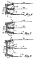
- Fig. 4 to 6 illustrate three different modes of connection of the generator according to fig. 3 on the protected line.
- This generator includes a power circuit for supplying a signal transmission circuit.
- connection terminals 16 and 17 come out.
- terminal 16 supplies a capacitor 19 which is mounted in series with an anti-overvoltage protection resistor 20 and which is connected, also in series, to the primary of an isolation transformer 21.
- a Zener diode 22 is provided for charging a capacitor 23 supplied through the secondary of the transformer 21 and suitable for forming a reservoir of energy.
- This capacitor 23 is connected to the conductor 24 connected to the terminal 17 in order to achieve, at the same time as the secondary of the transformer 21, at a MOS of power 25.
- the power circuit further comprises a circuit 26 for demagnetizing the transformer 21, as well as a varistor 27 placed between the terminal of the capacitor 19 on the resistance side 20 (linked to terminal 16) and the conductor 24 (linked to the opposite terminal 17 ).
- the signal transmission circuit comprises, in addition to the MOS 25, a low-voltage circuit 25 a (5 Volts for example) supplied by its own low-voltage supply.
- the latter is constituted by a Zener diode 28 connected in series with the diode 22 (these two diodes 22 and 28 being of the "transorb" type), and by a capacitor or capacitor 29 connected in parallel with said diode 28.
- This low circuit voltage 25 a for controlling the MOS 25 is clocked at the nominal frequency of the line envisaged, the voltage being for example taken from the terminals of a resistor 30 situated in the branch of the capacitor 23.
- the control circuit 25 a equipped with adjustment switches 25 b for the precise coding of the transmitted signal, is permanently supplied by the aforementioned power circuit, but its operation is initiated using a triggering member 31 placed under the dependence of the disconnector 7 of at least one surge arrester 5.
- a generator is provided for all the surge arresters 5 which equip the same transformer 3 of the line or the same end of each underground portion 6 thereof.
- the references 32, 33 and 34 designate the three phases of a conventional three-phase line and it will be observed that in the three solutions envisaged, the triggering member 31 is constituted by a mechanical element in the form of electrical conductor, flexible link or optical fiber which is successively engaged through an eyelet 13 a (see fig. 2) formed in the ejectable element 13 of each of the three arresters 5 fitted to the Line at point 3 or 6 considered.
- this generator will emit, at a frequency higher than the nominal, a coded signal which will be transmitted to the source station 1 of the line by one of the phases 32, 33 or 34 and / or the earth itself. , and this through the capacitor 19 which, at the selected transmission frequency, has a very low impedance.
- This coded signal informs the source station 1 on the one hand of the failure of one of the surge arresters 5 (this existence information is maintained until manual intervention at the level of the defective arrester), on the other hand of the exact identity of the arrester which is to be replaced.
- the generator does not contain any autonomous source of current or quartz since its power supply is directly drawn from the frequency of the protected line which supplies both the supply voltage of the control circuit and the reference frequency.
- connection between the triggering member 31 and the ejectable element 13 of each arrester can be operated in any suitable manner (connector, screw, bonding, etc.), the eyelet system 13 has n ' having been retained for illustrative purposes only.
Abstract
Description
La présente invention a trait aux parafoudres qui équipent les lignes électriques de distribution à moyenne tension destinées à l'alimentation des réseaux d'utilisation.The present invention relates to surge arresters which equip medium voltage distribution lines intended for supplying user networks.
On sait que le nombre des parafoudres montés sur une même ligne est très élevé. Ainsi qu'on l'a très schématiquement illustré à la fig. 1 du dessin annexé aux présentes, laquelle est un schéma très partiel du tracé d'une ligne classique, un poste source 1 alimente, à travers des disjoncteurs-sectionneurs 2, une série de transformateurs 3 dont chacun est relié à un ou plusieurs utilisateurs 4. Trois parafoudres 5 sont associés à chacun de ces transformateurs 3 ; en outre trois parafoudres 5 sont encore prévus à chacune des extrémités des portions souterraines 6 de la ligne.We know that the number of surge arresters mounted on the same line is very high. As very schematically illustrated in FIG. 1 of the drawing appended hereto, which is a very partial diagram of the layout of a conventional line, a
Pour la réalisation des parafoudres 5, on a à l'heure actuelle généralement recours à des pastilles céramiques d'oxyde de zinc (ZnO) ou de carbure de silicium, qui sont empilées sous pression entre deux électrodes de connexion prévues aux extrémités d'une enveloppe isolante de contention. Or l'expérience a démontré que la durée de vie d'un tel parafoudre est limitée par la céramique elle-même, laquelle devient conductrice après avoir encaissé un trop grand nombe de coups de foudre. Le parafoudre est alors à l'origine d'un courant de fuite même dans les conditions normales de courant et de tension, ce qui évidemment ne peut être toléré par l'exploitant.For the production of
Ce dernier est en conséquence confronté à deux problèmes, à savoir d'une part la détection de l'apparition, sur la ligne, du défaut provoqué par un parafoudre défaillant, d'autre part l'identification exacte de ce parafoudre défaillant en vue de son remplacement.The latter is consequently confronted with two problems, namely on the one hand the detection of the appearance, on the line, of the fault caused by a faulty arrester, on the other hand the exact identification of this faulty arrester with a view to its replacement.
Actuellement la détection du défaut sur la ligne est opérée par repérage du courant de court-circuit. Pour le second problème relatif à l'identification du parafoudre défaillant, on a proposé de doter les appareils d'un dispositif dénommé de signalisation de défaut 7 qui permet à un observateur situé à au plus 30 mètres de désigner visuellement le parafoudre qui est en défaut. A la manière illustrée à la fig. 2 du dessin annexé, un tel signalisateur 7 est fixé à l'une des platines d'extrémités 8 prévues de part et d'autre de l'enveloppe isolante 9 du parafoudre 5 pour supporter les pièces 10 qui assurent la connexion de l'appareil à l'une des phases de la ligne et à la terre. L'une de ces pièces 10 est donc fixée au corps 11 du signalisateur 7, lequel est pourvu d'un élément éjectable 13 relié par une tresse souple 14 à ladite platine 8.Currently, fault detection on the line is carried out by identifying the short-circuit current. For the second problem relating to the identification of the faulty surge arrester, it has been proposed to equip the devices with a device called fault signaling 7 which allows an observer located at most 30 meters to visually designate the surge arrester that is in default . As illustrated in FIG. 2 of the accompanying drawing, such a signaler 7 is fixed to one of the
En utilisation normale, l'ensemble 13-14 assure la jonction entre la pièce 10, qu'on supposera reliée à l'une des phases de la ligne à protéger, et l'empilage de pastilles céramique renfermé par l'enveloppe 9. Si la foudre tombe sur la phase envisagée, la surtension s'applique à l'empilage précité à travers l'ensemble 13-14. Si cet empilage est défaillant, le courant de fuite provoque la mise à feu d'une petite charge explosive logée dans le corps 11 du signalisateur 7, ce qui a pour effet d'expulser latéralement l'elément 13, l'ensemble 13-14 précité affectant alors la position qui a été représentée en 13'-14' .In normal use, the assembly 13-14 provides the junction between the
Un tel système est avantageux, puisqu'il permet l'identification du parafoudre qui est en défaut moyennenant observation visuelle de la position de l'ensemble 13'-14' .Such a system is advantageous, since it allows the identification of the arrester which is in default by means of visual observation of the position of the assembly 13'-14 '.
En outre il oblige l'exploitant de la ligne à procéder au remplacement du parafoudre défectueux avant la remise sous tension de ladite ligne.In addition, it obliges the operator of the line to replace the defective surge arrester before powering up the said line.
Toutefois, à ces avantages correspond un inconvénient sensible, lié au fait que la signalisation de défaut entraîne une coupure de longue durée (temps nécessaire à un observateur pour le contrôle visuel de l'ensemble des parafoudres de la ligne) privant les utilisateurs du service attendu.However, these advantages correspond to a significant drawback, linked to the fact that the fault signaling causes a long-term cut-off (time required for an observer to visually check all the surge arresters on the line) depriving users of the expected service .
C'est à ce problème du maintien de l'indication de défaut des parafoudres sans coupure de service que la présente invention entend apporter une solution, et ce à l'aide d'un générateur de signal électrique propre à faire remonter l'information de défaut d'un parafoudre déterminé jusqu'au poste-source qui alimente le tronçon portant ledit parafoudre ainsi identifié, étant observé que le générateur en question est associé à un déconnecteur de signalisation de sorte que le fonctionnement de ce dernier provoque l'émission du signal et isole le parafoudre défectueux de la terre.It is to this problem of maintaining the fault indication of the surge arresters without interruption of service that the present invention intends to provide a solution, and this using an electrical signal generator capable of bringing up the information of fault of a determined surge arrester up to the source station which supplies the section carrying said surge arrester thus identified, it being observed that the generator in question is associated with a signaling disconnector so that the operation of the latter causes the emission of the signal and isolates the defective arrester from the ground.
Le générateur de signal suivant l'invention est défini à la revendication 1.The signal generator according to the invention is defined in
L'originalité principale de ce générateur réside dans le fait qu'il comprend, pour l'alimentation permanente d'un circuit d'émission d'un signal codé dont l'entrée en fonctionnement est placée sous la dépendance d'un organe de déclenchement lié à l'élément éjectable d'au moins un parafoudre, un circuit de puissance qui incorpore un condensateur de couplage présentant une très forte impédance à la fréquence nominale de la ligne considérée à laquelle il est relié, mais au contraire une faible impédance à une fréquence plus élevée, de façon à ce que le signal codé finalement émis soit transmis au poste-source par la ligne elle-même ou par la terre.The main originality of this generator lies in the fact that it comprises, for the permanent supply of a circuit for transmitting a coded signal whose entry into operation is placed under the dependence of a triggering member. linked to the ejectable element of at least one surge arrester, a power circuit which incorporates a coupling capacitor having a very high impedance at the nominal frequency of the line considered to which it is connected, but on the contrary a low impedance at a higher frequency, so that the coded signal finally transmitted is transmitted to the source station by the line itself or by the ground.
Le dessin annexé, donné à titre d'exemple, permettra de mieux comprendre l'invention, les caractéristiques qu'elle présente et les avantages qu'elle est susceptible de procurer :The appended drawing, given by way of example, will allow a better understanding of the invention, the characteristics which it presents and the advantages which it is capable of providing:
Comme indiqué ci-dessus, fig. 1 est un schéma illustrant partiellement le tracé d'une ligne classique équipée de parafoudres, tandis que fig. 2 montre en élévation un parafoudre classique du type à déconnecteur signalisateur de défaut.As indicated above, fig. 1 is a diagram partially illustrating the layout of a conventional line equipped with surge arresters, while fig. 2 shows in elevation a conventional surge arrester of the type with disconnector signaling a fault.
Fig. 3 représente le schéma d'un générateur de signal établi conformément à la présente invention.Fig. 3 shows the diagram of a signal generator established in accordance with the present invention.
Fig. 4 à 6 illustrent trois modes différents de branchement du générateur suivant fig. 3 sur la ligne protégée.Fig. 4 to 6 illustrate three different modes of connection of the generator according to fig. 3 on the protected line.
Ce générateur comprend un circuit de puissance pour l'alimentation d'un circuit d'émission de signal.This generator includes a power circuit for supplying a signal transmission circuit.
Du boîtier 15 de ce générateur sortent deux bornes de branchement 16 et 17. Par un conducteur 18 la borne 16 alimente un condensateur 19 qui est monté en série avec une résistance de protection anti-surtension 20 et qui est relié, également en série, au primaire d'un transformateur d'isolement 21. En série avec le condensateur 19, dont l'impédance est très forte à la tension nominale, est prévue une diode Zener 22 pour le chargement d'un condensateur 23 alimenté à travers le secondaire du transformateur 21 et propre à former résevoir d'énergie. Ce condensateur 23 est relié au conducteur 24 branché à la borne 17 afin d'aboutir, en même temps que le secondaire du transformateur 21, à un MOS de puissance 25.From the
Le circuit de puisance comprend encore un circuit 26 pour la démagnétisation du transformateur 21, ainsi qu'une varistance 27 placée entre la borne du condensateur 19 côté résistance 20 (liée à la borne 16) et le conducteur 24 (lié à la borne opposée 17).The power circuit further comprises a
Le circuit d'émission de signal comprend, outre le MOS 25, un circuit 25a à basse-tension (5 Volts par exemple) alimenté par sa propre alimentation basse-tension. Cette dernière est constituée par une diode Zener 28 branchée en série avec la diode 22 (ces deux diodes 22 et 28 étant du type "transorb"), et par un condensateur ou capacité 29 branché en parallèle avec ladite diode 28. Ce circuit basse-tension 25a pour la commande du MOS 25 est cadencé sur la fréquence nominale de la ligne envisagée, la tension étant par exemple prélevée aux bornes d'une résistance 30 située dans la branche du condensateur 23.The signal transmission circuit comprises, in addition to the
Le circuit de commande 25a, équipé d'interrupteurs de réglage 25b pour le codage précis du signal émis, est alimenté en permanence par le circuit de puissance précité, mais son fonctionnement est initié à l'aide d'un organe de déclenchement 31 placé sous la dépendance du déconnecteur 7 d'au moins un parafoudre 5. En fait, pour des raisons évidentes d'économie, on prévoit un générateur pour tous les parafoudres 5 qui équipent un même transformateur 3 de la ligne ou une même extrémité de chaque portion souterraine 6 de celle-ci.The control circuit 25 a , equipped with
Sur les schémas de branchement illustrés en fig. 4, 5 et 6, les références 32, 33 et 34 désignent les trois phases d'une ligne triphasée classique et l'on obsevera que dans les trois solutions envisagées, l'organe de déclenchement 31 est constitué par un élément mécanique en forme de conducteur électrique, de lien souple ou de fibre optique qui, est successivement engagé à travers un oeillet 13a (voir fig. 2) ménagé dans l'élément éjectable 13 de chacun des trois parafoudres 5 équipant la Ligne au point 3 ou 6 considéré.On the connection diagrams illustrated in fig. 4, 5 and 6, the
On conçoit sans peine que si l'un quelconque de ces trois parafoudres 5 est défaillant à la suite d'un coup de foudre, l'éjection de son élément 13 va avoir pour effet de sectionner l'organe 31 et de provoquer ainsi le déclenchement du fonctionnement du circuit 25a du générateur qui équipe le point de ligne considéré.It is easy to see that if any one of these three
Dans ces conditions ce générateur va émettre, à une fréquence plus élevée que la nominale, un signal codé qui sera transmis au poste-source 1 de la ligne par l'une des phases 32, 33 ou 34 et/ou la terre elle-même, et ce à travers le condensateur 19 qui, à la fréquence d'émission choisie, présente une impédance très faible. Ce signal codé informe le poste-source 1 d'une part de la défaillance de l'un des parafoudres 5 (cette information d'existence se maintenant jusqu'à intervention manuelle au niveau du parafoudre défaillant), d'autre part de l'identité exacte du parafoudre qui est à remplacer.Under these conditions, this generator will emit, at a frequency higher than the nominal, a coded signal which will be transmitted to the
Les trois modes de branchement du générateur tels qu'illustrés en fig. 4 à 6 présentent des inconvénients et des avantages respectifs :
- en fig. 4 les
bornes 16 et 17 du générateur ont été supposées branchées sur lesphases 32 et 33, de sorte que l'impédance de la ligne, parfaitement connue, permet d'adopter une puissance inférieure tout en obtenant une transmission d'excellente qualité ; par contre leboîtier 15 n'est pas mis à la masse, ce qui peut gêner les opérations de branchement. - en fig. 5 les
bornes 16 et 17 du générateur sont reliées à laphase 32 et à la terre par l'intermédiaire du poteau-support 35, ce qui facilite les opérations de branchement, en même temps que le coût reste bas ; par contre l'impédance est mal définie car la conductivité du sol est mal connue, et le plus grand éloignement des conducteurs conduit à davantage de rayonnement électromagnétique à proximité de la ligne - enfin en fig. 6 le générateur est agencé sous forme double pour alimenter en opposition de phases les deux lignes formées de la terre et des
phases 32 et 33 tout en étant mis à la masse à travers le poteau-support 35. On combine tous les avantages cidessus évoqués, mais le coût de fabrication est évidemment plus élevé.
- in fig. 4 the
terminals phases housing 15 is not grounded, which can hinder the connection operations. - in fig. 5 the
terminals phase 32 and to the earth via thesupport post 35, which facilitates connection operations, at the same time as the cost remains low; on the other hand the impedance is poorly defined because the conductivity of the ground is poorly known, and the greater distance of the conductors leads to more electromagnetic radiation near the line - finally in fig. 6 the generator is arranged in double form to supply in opposition of phases the two lines formed of the earth and of
phases support post 35. All the advantages mentioned above are combined, but the manufacturing cost is obviously higher.
Dans tous les cas le générateur ne renferme aucune source autonome de courant ni quartz puisque son alimentation est directement tirée de la fréquence de la ligne protégée qui fournit à la fois la tension d'alimention du circuit de commande et la fréquence de référence.In all cases the generator does not contain any autonomous source of current or quartz since its power supply is directly drawn from the frequency of the protected line which supplies both the supply voltage of the control circuit and the reference frequency.
On conçoit que la liaison entre l'organe de déclenchement 31 et l'élément éjectable 13 de chaque parafoudre peut être opérée de toute manière appropriée (connecteur, vis, collage, etc...), le système d'oeillet 13a n'ayant été retenu qu'à titre illustratif.It is understood that the connection between the triggering
Claims (9)
Applications Claiming Priority (2)
| Application Number | Priority Date | Filing Date | Title |
|---|---|---|---|
| FR9206158 | 1992-05-15 | ||
| FR9206158A FR2691301B1 (en) | 1992-05-15 | 1992-05-15 | SIGNAL GENERATOR FOR TELE-DETECTION OF OPERATING FAULTS OF SURGE PROTECTORS MOUNTED ON ELECTRICAL DISTRIBUTION LINES. |
Publications (1)
| Publication Number | Publication Date |
|---|---|
| EP0570310A1 true EP0570310A1 (en) | 1993-11-18 |
Family
ID=9430000
Family Applications (1)
| Application Number | Title | Priority Date | Filing Date |
|---|---|---|---|
| EP93420194A Withdrawn EP0570310A1 (en) | 1992-05-15 | 1993-05-13 | Signal generator for the remote detection of functional failure of overvoltage protection devices mounted on electrical distribution lines |
Country Status (2)
| Country | Link |
|---|---|
| EP (1) | EP0570310A1 (en) |
| FR (1) | FR2691301B1 (en) |
Cited By (6)
| Publication number | Priority date | Publication date | Assignee | Title |
|---|---|---|---|---|
| WO1999005761A1 (en) * | 1997-07-22 | 1999-02-04 | Scientific-Atlanta, Inc. | Surge protectors that indicate failure to a remote location |
| GB2349993A (en) * | 1999-03-23 | 2000-11-15 | John Edward Cunningham | Fault location |
| CN101102055B (en) * | 2006-07-07 | 2010-12-08 | 上海雷迅防雷技术有限公司 | System for monitoring the surge protector based on distribution line and its method |
| CN101153883B (en) * | 2006-09-29 | 2011-01-12 | 上海雷迅防雷技术有限公司 | Method for data access of surge protector and monitoring system of surge protector |
| CN101515718B (en) * | 2009-01-13 | 2011-04-27 | 上海雷迅防雷技术有限公司 | Remote alarm method and a system of a surge protector |
| US8823387B1 (en) | 2011-03-11 | 2014-09-02 | Electro-Mechanical Corporation | Blown fuse detector |
Citations (4)
| Publication number | Priority date | Publication date | Assignee | Title |
|---|---|---|---|---|
| US2337441A (en) * | 1941-07-03 | 1943-12-21 | John F Atkinson | Outage indicator |
| US2863141A (en) * | 1956-12-26 | 1958-12-02 | Lotran Inc | Transmission system outage locator |
| EP0246644A2 (en) * | 1986-05-23 | 1987-11-25 | DODUCO KG. Dr. Eugen Dürrwächter | Device for recording current-impulses which go through the earth-circuit of overvoltage arresters in high-voltage networks |
| EP0386288A1 (en) * | 1989-03-07 | 1990-09-12 | Siemens Aktiengesellschaft | Device for monitoring electronic circuits or components |
-
1992
- 1992-05-15 FR FR9206158A patent/FR2691301B1/en not_active Expired - Fee Related
-
1993
- 1993-05-13 EP EP93420194A patent/EP0570310A1/en not_active Withdrawn
Patent Citations (4)
| Publication number | Priority date | Publication date | Assignee | Title |
|---|---|---|---|---|
| US2337441A (en) * | 1941-07-03 | 1943-12-21 | John F Atkinson | Outage indicator |
| US2863141A (en) * | 1956-12-26 | 1958-12-02 | Lotran Inc | Transmission system outage locator |
| EP0246644A2 (en) * | 1986-05-23 | 1987-11-25 | DODUCO KG. Dr. Eugen Dürrwächter | Device for recording current-impulses which go through the earth-circuit of overvoltage arresters in high-voltage networks |
| EP0386288A1 (en) * | 1989-03-07 | 1990-09-12 | Siemens Aktiengesellschaft | Device for monitoring electronic circuits or components |
Cited By (6)
| Publication number | Priority date | Publication date | Assignee | Title |
|---|---|---|---|---|
| WO1999005761A1 (en) * | 1997-07-22 | 1999-02-04 | Scientific-Atlanta, Inc. | Surge protectors that indicate failure to a remote location |
| GB2349993A (en) * | 1999-03-23 | 2000-11-15 | John Edward Cunningham | Fault location |
| CN101102055B (en) * | 2006-07-07 | 2010-12-08 | 上海雷迅防雷技术有限公司 | System for monitoring the surge protector based on distribution line and its method |
| CN101153883B (en) * | 2006-09-29 | 2011-01-12 | 上海雷迅防雷技术有限公司 | Method for data access of surge protector and monitoring system of surge protector |
| CN101515718B (en) * | 2009-01-13 | 2011-04-27 | 上海雷迅防雷技术有限公司 | Remote alarm method and a system of a surge protector |
| US8823387B1 (en) | 2011-03-11 | 2014-09-02 | Electro-Mechanical Corporation | Blown fuse detector |
Also Published As
| Publication number | Publication date |
|---|---|
| FR2691301A1 (en) | 1993-11-19 |
| FR2691301B1 (en) | 1994-07-08 |
Similar Documents
| Publication | Publication Date | Title |
|---|---|---|
| EP0493272B1 (en) | Circuit breaker containing an interface card with a trip device | |
| EP1187290A1 (en) | Overvoltage protection device | |
| FR2680611A1 (en) | DEVICE FOR PROTECTION AGAINST OVERVOLTAGES. | |
| FR2815767A1 (en) | Disconnect switch with built-in fuse, e.g. for telecommunication panel system, has fuse receptacle to retractably hold fuse with open fuse indicator in switch housing | |
| EP1447831B1 (en) | Device for protecting against overvoltage due to lightning | |
| BE897439A (en) | PROTECTION AGAINST OVERVOLTAGES | |
| EP0570310A1 (en) | Signal generator for the remote detection of functional failure of overvoltage protection devices mounted on electrical distribution lines | |
| FR2641138A1 (en) | ||
| EP0347304B1 (en) | Electric measuring transformer | |
| EP0130851B1 (en) | Protection apparatus against overvoltages in electrical low-voltage installations or networks | |
| EP0521805B1 (en) | Defect indicator for arrester | |
| EP0085074B1 (en) | Protection device against over-voltage in an electric distribution network | |
| EP0845843B1 (en) | Protection device for telephone lines | |
| EP0676845A1 (en) | Overvoltage protection system | |
| EP0647005B1 (en) | Parallel and series protection module | |
| WO2002048724A1 (en) | System for detecting failure of a cable in a tree-structure network | |
| FR2517150A1 (en) | MICROPROCESSOR MANAGED MICROPROCESSOR CIRCUIT WITH INTEGRATED 2-WIRE 4-WIRE TRANSMISSION CIRCUIT AND CURRENT LINE BACKUP POWER SUPPLY | |
| FR2576720A1 (en) | Safety electrical extension | |
| EP0776117B1 (en) | Surge protection device for a telephone installation | |
| FR2644014A1 (en) | ARRANGEMENT FOR LIMITING ELECTRICAL OVERVOLTAGES | |
| FR2659504A1 (en) | Safety container for lightning (surge) arrester for protecting a telephone line | |
| FR2655420A2 (en) | DEVICE FOR THE SEALING CONTROL OF A NETWORK OF METALLICALLY SHEATHED OPTICAL FIBER CABLES. | |
| EP0755107A1 (en) | Communication circuit for fault indication and test module used therewith | |
| FR2737056A1 (en) | PROTECTION MODULE WITH DEFECT SIGNALING AND PROTECTION CONNECTION ASSEMBLY | |
| EP0025404A2 (en) | Short-circuiting element for series supply circuit |
Legal Events
| Date | Code | Title | Description |
|---|---|---|---|
| PUAI | Public reference made under article 153(3) epc to a published international application that has entered the european phase |
Free format text: ORIGINAL CODE: 0009012 |
|
| AK | Designated contracting states |
Kind code of ref document: A1 Designated state(s): AT BE CH DE DK ES FR GB GR IE IT LI LU MC NL PT SE |
|
| 17P | Request for examination filed |
Effective date: 19940210 |
|
| 17Q | First examination report despatched |
Effective date: 19951020 |
|
| GRAG | Despatch of communication of intention to grant |
Free format text: ORIGINAL CODE: EPIDOS AGRA |
|
| GRAH | Despatch of communication of intention to grant a patent |
Free format text: ORIGINAL CODE: EPIDOS IGRA |
|
| STAA | Information on the status of an ep patent application or granted ep patent |
Free format text: STATUS: THE APPLICATION IS DEEMED TO BE WITHDRAWN |
|
| 18D | Application deemed to be withdrawn |
Effective date: 19960918 |