EP0569656B1 - Apparatus for the closure of two-part capsules - Google Patents
Apparatus for the closure of two-part capsules Download PDFInfo
- Publication number
- EP0569656B1 EP0569656B1 EP92830210A EP92830210A EP0569656B1 EP 0569656 B1 EP0569656 B1 EP 0569656B1 EP 92830210 A EP92830210 A EP 92830210A EP 92830210 A EP92830210 A EP 92830210A EP 0569656 B1 EP0569656 B1 EP 0569656B1
- Authority
- EP
- European Patent Office
- Prior art keywords
- capsule
- liquid
- parts
- organ
- absorbent
- Prior art date
- Legal status (The legal status is an assumption and is not a legal conclusion. Google has not performed a legal analysis and makes no representation as to the accuracy of the status listed.)
- Expired - Lifetime
Links
Images
Classifications
-
- A—HUMAN NECESSITIES
- A61—MEDICAL OR VETERINARY SCIENCE; HYGIENE
- A61J—CONTAINERS SPECIALLY ADAPTED FOR MEDICAL OR PHARMACEUTICAL PURPOSES; DEVICES OR METHODS SPECIALLY ADAPTED FOR BRINGING PHARMACEUTICAL PRODUCTS INTO PARTICULAR PHYSICAL OR ADMINISTERING FORMS; DEVICES FOR ADMINISTERING FOOD OR MEDICINES ORALLY; BABY COMFORTERS; DEVICES FOR RECEIVING SPITTLE
- A61J3/00—Devices or methods specially adapted for bringing pharmaceutical products into particular physical or administering forms
- A61J3/07—Devices or methods specially adapted for bringing pharmaceutical products into particular physical or administering forms into the form of capsules or similar small containers for oral use
- A61J3/071—Devices or methods specially adapted for bringing pharmaceutical products into particular physical or administering forms into the form of capsules or similar small containers for oral use into the form of telescopically engaged two-piece capsules
- A61J3/072—Sealing capsules, e.g. rendering them tamper-proof
Definitions
- the invention relates to a device for closing capsules in two parts, for example capsules for medicinal use, comprising support means for an upper part of the capsule and means for applying to said upper part of the capsule d 'A liquid intended to cause the reciprocal junction between the upper part of the capsule and the lower part thereof.
- the invention also relates to a method for closing capsules in two parts, for example capsules for medicinal use, comprising the phases of dispensing on one of the two parts of the capsule a liquid intended to cause the reciprocal joining of the two parts of the capsule and then of union of the two parts of the capsule to cause the junction by gluing.
- capsules made of gelatin or, according to the most recent technique, of starch are frequently used as containers for powdered medicaments. These capsules have a first part or body, inside which the powder to be packaged is introduced, and an upper closing cap which must be threaded onto the body and welded to it.
- liquids of various kinds are used, depending on the type of substance used to make the capsule.
- a machine for closing capsules in two parts intended to be united after application of a liquid intended to cause the connection between the upper part of each capsule and the lower part which comprises a felt mat intended to be soaked with said liquid, means for supporting, individually, in the vertical position and above the aforementioned mat, the upper part of each capsule, means for moving the upper part of each capsule in the vertical direction, between a high waiting position and a low contact position on said mat to allow the application of the liquid on its internal wall.
- the upper part of each capsule is pushed in the vertical direction until it comes into contact with the mat soaked in liquid joining the two parts of the capsule.
- the pressure thus exerted on the belt causes it to contact the upper part of the capsule and, in this way, the application of the liquid thereon.
- this system entails the serious and inevitable drawback of causing the external wall of the capsule half pushed onto the carpet to wetting, that is to say that it does not allow the application of the liquid only on the internal wall. of it.
- This also leads to the need to remove the excess liquid on the outside of the capsules after the union of the upper part with the lower part, to avoid their mutual gluing before packaging.
- the object of the present invention is to provide a device of the type mentioned in the preamble of the main claim, which makes it possible to obtain correct application of the liquid to the upper part of the capsule in a simpler and more reliable manner than for traditional type devices.
- the device according to the invention is based on the principle of applying the liquid, which uses application means comprising an absorbent member which capillarily takes the liquid from a container and distributes it over the upper part of the capsule. , in correspondence of the junction edge of said upper part with the body of the capsule. Therefore, the device according to the invention does not include means for compressing the liquid or means for sucking it. Furthermore, it is not necessary to produce mechanical members of small dimensions with spray nozzles and suction orifices, as is necessary in devices of known type. The whole process of taking the liquid and applying it is carried out passively by exploiting the physical characteristics of an absorbent means, which can consist, for example, of a chamois synthetic skin, cotton fiber or similar material. .
- the device of the invention comprises a rod corresponding to the upper end of which is arranged an element of absorbent material which receives the liquid by capillary action from a reservoir placed below.
- an element of absorbent material which receives the liquid by capillary action from a reservoir placed below.
- a discoidal element of absorbent material In correspondence of said upper end of the rod can be disposed a discoidal element of absorbent material, the diameter of which corresponds to the diameter of the edge of the upper internal part of the capsule, so that the latter can cover the discoidal element and be uniformly wetted by it along the entire circumference of the coupling edge with the body of the capsule.
- the discoidal element of absorbent material is also in contact with a linear band-shaped element which extends along the rod from said upper end to a reservoir placed below, for the withdrawal of the liquid. contained in said tank.
- the longitudinal element can be produced in the form of a band housed in longitudinal seats formed in a central housing axis, surrounded by an external cylindrical closure member.
- the upper part of the capsule must be removed by a supply device by means of an appropriate support means which makes it possible to present said capsule part successively to the means for applying the liquid and then to the body of the capsule beforehand. filled with powder or other substance to be packaged.
- the support means may include, in accordance with the invention, a cavity or a housing provided with an annular seal, into which the upper part of the capsule can be inserted with slight interference under the effect of a simple movement of lowering of the support means on the part capsule predisposed on the feeding device.
- the annular seal maintains the upper part of the capsule for the entire time necessary for the application of the liquid on the edge thereof and until the upper part of the capsule adheres to the body of the capsule.
- the upper part of the capsule is dislodged from this cavity; said upper part remains adherent to the capsule body suitably supported in a retaining seat.
- a carrier member equipped with one or more of said support means and designed to be positioned in a first position in correspondence with a device for feeding the upper parts of the capsule and a second position. in correspondence with the corresponding means for applying the liquid. From this position, after having wetted the edge of all the capsule parts supported by the different support means of the carrier member, the latter is moved by translation into a third position in correspondence with corresponding means supporting the body or lower part of the capsule. The lowering of the carrier member equipped with the means for supporting the upper capsule parts causes all the capsule bodies placed below to be closed simultaneously.
- the reference number 1 indicates a supply device on which there are several closure capsules or part upper capsule S, from a suitable container. Each of these parts S is removed by a corresponding support means indicated generically by 3 and shown in more detail in FIG. 2.
- a support member 5 for example in the form of a bar extending perpendicular to the plane of the drawing, on which a series of support means is applied 3.
- the support means 3 of the capsule part S comprises a cylindrical member 7 forming a cavity 9 with a groove 11 in which is housed an annular seal 13 and of circular section.
- the support means 3 When the support means 3 is threaded onto the capsule part S, the latter enters the cavity 9 and it is retained with slight interference by the seal 13 in the position shown in FIG. 3.
- the upper part S of the capsule has an edge of lower thickness, intended to be threaded on a corresponding upper edge of a capsule body shown in particular in FIG. 7 and indicated by C.
- the liquid used can be water, or a solution of water and alcohol or a similar liquid, which causes a softening or partial dissolution of the starch in the zone d 'application.
- the edge B of the capsule part S has been thus moistened and therefore partially dissolved or softened, it can be threaded onto the upper edge of the capsule body C in such a way that the successive drying of the starch causes the junction of the two parts C and S and tightly encloses the content P of the capsule.
- the means 15 comprises a rod constituted by a central axis 17 and an external cylindrical member 19.
- the axis 17 has two diametrically opposite flats 21 which form, with a cylindrical chamber 23 delimited by the member cylindrical 19, two longitudinal seats for a strip of absorbent material indicated by 25.
- the strip 25 is arranged in a U inside the two diametrically opposite seats 21, while in an intermediate section of the said strip is provided a hole, so that the strip 25 can be threaded onto the end 29 of the axis 17 having a reduced diameter, in order to be maintained in a predetermined position relative to axis 17.
- a threaded hole In the end 29 and in a part of the body of axis 17 is provided a threaded hole in which s' engages a screw 31 intended to block on the axis 17 an end element 33.
- a discoid element 35 of absorbent material identical or similar to the material of the strip 25 , with which said discoid element is in direct contact.
- the screw 31 clamps the end element 33 on the rod 17 so as to maintain the discoid element 35 in close contact with the strip 25 for the purposes indicated below.
- the length of the end 29 and the thickness of the material forming the strip 25 and the element Discoid 35 can be appropriately calibrated to clamp the absorbent material with the desired force and thereby obtain the distribution of the correct amount of liquid.
- the application means 15 is supported by a cross member 37 which can carry a plurality of said application means 15 arranged in a row or on several rows, and in all cases according to an arrangement corresponding to the arrangement of the support means 3 which are presented above the means 15 and lowered thereon to bring the upper parts S of the capsule into contact with the different discoid elements 33 arranged in correspondence with the ends of the different application means 15 carried by the cross-member 37.
- Au- below the cross-member 37 is provided a container (not shown) in which is contained the liquid L which must be applied uniformly to the edge B of the parts S of the capsule.
- the strip 25 has a length such that its ends 25E are always immersed in the liquid L, which is removed by capillary action and goes up along the two branches of the strip 25 until it impregnates the discoid element 35. Consequently, when an upper part S of the capsule is threaded on the discoid element 35 (which protrudes appropriately from the external profile of the rod formed by the members 17, 19 and 33), on the annular edge B of said part S is uniformly distributed a sufficient amount of liquid L to cause softening or partial dissolution of the material constituting the capsule.
- the carrier member 5 with the support means 3 can be lifted and moved by translation until arriving in correspondence with a member 40 which has a plurality of seats 42 in which are housed the body C of the capsules which must be closed by means of the upper parts S suitably wetted along their edges B.
- the support means 37 are then lifted to thread the parts S of capsule on the body of capsule C and thus premature the closing of the capsules themselves.
- Fig. 7 shows the closing phase of the capsules.
- the carrying member 5 can be lifted according to the arrow f5 from the position of FIG. 7 to release the part S of the seat 9.
- the disengagement of the upper part S of the capsule from the seat 9 can be facilitated by means of an extractor or an overpressure created in said seat 9, by acting through the orifice placed above (Fig. 2).
- the various capsules are closed hermetically and ready to be packaged. They are extracted from the member 40 by means of an appropriate extractor or the like.
- the device according to the invention can be used not only for closing starch capsules which require the application of solvent liquids (such as water or mixtures of water and alcohol or the like), but also in all other cases in which, for closing the capsule, it is necessary to apply a liquid whose physical properties are such that they allow withdrawal from a reservoir by capillary action.
- the 'discoid element 35 could be compressed cyclically between the upper edge of the fixed cylindrical member 19 and the movable nozzle 33, each time the liquid is applied to the upper part S of the capsule. The pressing of the discoid element 35 causes the distribution of a greater quantity of liquid.
Abstract
Description
La invention se réfère à un dispositif pour la fermeture de capsules en deux parties, par exemple des capsules pour usage médicinal, comprenant un moyen de support pour une partie supérieure de la capsule et des moyens d'application sur ladite partie supérieure de la capsule d'un liquide destiné à provoquer la jonction réciproque entre la partie supérieure de la capsule et la partie inférieure de celle-ci.The invention relates to a device for closing capsules in two parts, for example capsules for medicinal use, comprising support means for an upper part of the capsule and means for applying to said upper part of the capsule d 'A liquid intended to cause the reciprocal junction between the upper part of the capsule and the lower part thereof.
L'invention concerne également un procédé pour la fermeture de capsules en deux parties, par exemple des capsules pour usage médicinal, comprenant les phases de distribution sur une des deux parties de capsule d'un liquide destiné à provoquer la jonction réciproque des deux parties de la capsule et ensuite d'union des deux parties de la capsule pour en provoquer la jonction par collage.The invention also relates to a method for closing capsules in two parts, for example capsules for medicinal use, comprising the phases of dispensing on one of the two parts of the capsule a liquid intended to cause the reciprocal joining of the two parts of the capsule and then of union of the two parts of the capsule to cause the junction by gluing.
Dans le domaine pharmaceutique, on utilise fréquemment, comme récipients de médicaments en poudre, des capsules réalisées en gélatine ou, selon la technique la plus récente, en amidon. Ces capsules présentent une première partie ou corps, à l'intérieur de laquelle est introduite la poudre à conditionner, et une calotte supérieure de fermeture qui doit être enfilée sur le corps et soudée à celui-ci. Pour le soudage ou la jonction des deux parties de la capsule, on utilise des liquides de diverse nature, en fonction du type de substance employée pour la réalisation de la capsule. Par exemple, dans le cas de capsules réalisées en amidon, il suffit d'appliquer sur le bord interne de la partie supérieure de la capsule une faible quantité d'eau ou d'un autre solvant, qui provoque un ramollissement de l'amidon. En enfilant ensuite la partie supérieure de la capsule sur le corps de celle-ci et en faisant sécher, on obtient une fermeture efficace et fiable de la capsule elle-même.In the pharmaceutical field, capsules made of gelatin or, according to the most recent technique, of starch are frequently used as containers for powdered medicaments. These capsules have a first part or body, inside which the powder to be packaged is introduced, and an upper closing cap which must be threaded onto the body and welded to it. For welding or joining the two parts of the capsule, liquids of various kinds are used, depending on the type of substance used to make the capsule. For example, in the case of capsules made of starch, it is sufficient to apply to the inner edge of the upper part of the capsule a small amount of water or of another solvent, which causes softening of the starch. By then threading the upper part of the capsule on the body thereof and drying, one obtains an effective and reliable closure of the capsule itself.
Pour obtenir une fermeture correcte de la capsule et pour éviter une détérioration aussi bien du contenu de la capsule que de son enveloppe externe, il est nécessaire que le moyen liquide appliqué pour la jonction successive des deux parties soit distribué de manière uniforme et en quantité correcte, en éliminant l'excédent susceptible de provoquer l'adhésion des capsules adjacentes ou encore une détérioration du contenu de la capsule elle-même.
Dans ce but, on a étudié un dispositif (décrit dans DE-A-3735260) qui présente une série de buses qui vaporisent le liquide sur le bord de la partie supérieure de la capsule et un système d'aspiration qui aspire le surplus de liquide vaporisé sur la capsule avant de procéder à l'accouplement des deux parties. Ce dispositif est extrêmement complexe, entre autre parce qu'il nécessite des moyens de compression du liquide et des moyens d'aspiration de celui-ci.To obtain a correct closure of the capsule and to avoid deterioration both of the contents of the capsule and of its external envelope, it is necessary that the liquid means applied for the successive junction of the two parts is distributed uniformly and in correct quantity , by eliminating the excess likely to cause the adhesion of the adjacent capsules or even a deterioration of the contents of the capsule itself.
To this end, we have studied a device (described in DE-A-3735260) which has a series of nozzles which vaporize the liquid on the edge of the upper part of the capsule and a suction system which sucks off the excess liquid sprayed on the capsule before coupling the two parts. This device is extremely complex, among other things because it requires means for compressing the liquid and means for sucking it.
On connaît également d'après le brevet GB-A-2187703, une machine pour la fermeture des capsules en deux parties destinées à être unies après application d'un liquide destiné à provoquer la liaison entre la partie supérieure de chaque capsule et la partie inférieure, laquelle comprend un tapis en feutre destiné à être imbibé dudit liquide, des moyens pour supporter, individuellement, dans la position verticale et au dessus du tapis précité, la partie supérieure de chaque capsule, d,es moyens pour le déplacement de la partie supérieur de chaque capsule dans la direction verticale, entre une position haute d'attente et une position basse de contact sur ledit tapis pour permettre l'application du liquide sur sa paroi interne. La partie supérieure de chaque capsule est poussèe dans la direction verticale jusqu'à ce qu'elle vienne en contact avec le tapis imbibé de liquide de jonction des deux parties de la capsule. La pression ainsi exercée sur le tapis provoque son contact avec la partie supérieure de la capsule et, de cette manière, l'application du liquide sur celle-ci.
Mais ce système entraîne le grave et inévitable inconvénient de provoquer le mouillage de la paroi externe de la moitié de capsule poussée sur le tapis, c'est-à-dire qu'il ne permet pas l'application du liquide uniquement sur la paroi interne de celle-ci. Ceci entraîne, en outre, la nécessité d'éliminer le liquide en excès sur le coté extérieure des capsules après l'union de la partie supérieure avec la partie inférieure, pour éviter leur encollage réciproque avant le conditionnement.
Le but de la présente invention est de réaliser un dispositif du type mentionné dans le préambule de la revendication principale, qui permette d'obtenir une application correcte du liquide sur la partie supérieure de la capsule d'une manière plus simple et plus fiable que pour les dispositifs de type traditionnel.Also known from GB-A-2187703, a machine for closing capsules in two parts intended to be united after application of a liquid intended to cause the connection between the upper part of each capsule and the lower part , which comprises a felt mat intended to be soaked with said liquid, means for supporting, individually, in the vertical position and above the aforementioned mat, the upper part of each capsule, means for moving the upper part of each capsule in the vertical direction, between a high waiting position and a low contact position on said mat to allow the application of the liquid on its internal wall. The upper part of each capsule is pushed in the vertical direction until it comes into contact with the mat soaked in liquid joining the two parts of the capsule. The pressure thus exerted on the belt causes it to contact the upper part of the capsule and, in this way, the application of the liquid thereon.
However, this system entails the serious and inevitable drawback of causing the external wall of the capsule half pushed onto the carpet to wetting, that is to say that it does not allow the application of the liquid only on the internal wall. of it. This also leads to the need to remove the excess liquid on the outside of the capsules after the union of the upper part with the lower part, to avoid their mutual gluing before packaging.
The object of the present invention is to provide a device of the type mentioned in the preamble of the main claim, which makes it possible to obtain correct application of the liquid to the upper part of the capsule in a simpler and more reliable manner than for traditional type devices.
En réalité, le dispositif selon l'invention se base sur le principe d'application du liquide, lequel utilise des moyens d'application comprenant un organe absorbant qui prélève par capillarité le liquide dans un récipient et le distribue sur la partie supérieure de la capsule, en correspondance du bord de jonction de ladite partie supérieure avec le corps de la capsule. De ce fait, le dispositif selon l'invention ne comporte pas de moyens de compression du liquide ni des moyens d'aspiration de celui-ci. Par ailleurs, il n'est pas nécessaire de réaliser des organes mécaniques de petites dimensions avec buses de vaporisation et orifices d'aspiration, comme cela est nécessaire dans les dispositifs de type connu. Tout le processus de prélèvement du liquide et d'application de celui-ci s'effectue de manière passive en exploitant les caractéristiques physiques d'un moyen absorbant, qui peut être constitué par exemple par une peau synthétique chamoisée, fibre de coton ou matériau similaire.In reality, the device according to the invention is based on the principle of applying the liquid, which uses application means comprising an absorbent member which capillarily takes the liquid from a container and distributes it over the upper part of the capsule. , in correspondence of the junction edge of said upper part with the body of the capsule. Therefore, the device according to the invention does not include means for compressing the liquid or means for sucking it. Furthermore, it is not necessary to produce mechanical members of small dimensions with spray nozzles and suction orifices, as is necessary in devices of known type. The whole process of taking the liquid and applying it is carried out passively by exploiting the physical characteristics of an absorbent means, which can consist, for example, of a chamois synthetic skin, cotton fiber or similar material. .
Selon sa forme de réalisation de base, le dispositif de 'invention comprend une tige en correspondance de l'extrémité supérieure de laquelle est disposé un élément en matière absorbante qui reçoit le liquide par capillarité à partir d'un réservoir placé au-dessous. En correspondance de ladite extrémité supérieure de la tige peut être disposé un élément discoïde en matière absorbante, dont le diamètre correspond au diamètre du bord de la partie interne supérieure de la capsule, de telle manière que cette dernière puisse coiffer l'élément discoïde et être mouillée uniformément par celui-ci le long de toute la circonférence du bord d'accouplement avec le corps de la capsule. L'élément discoïde en matière absorbante est en outre en contact avec un élément linéaire en forme de bande qui s'étend le long de la tige à partir de ladite extrémité supérieure jusqu'à un réservoir placé au-dessous, pour le prélèvement du liquide contenu dans ledit réservoir. L'élément longitudinal peut être réalisé sous forme de bande logée dans des sièges longitudinaux pratiqués dans un axe central de logement, entouré par un organe cylindrique externe de fermeture.
La partie supérieure de la capsule doit être prélevée par un dispositif d'alimentation par l'intermédiaire d'un moyen de support approprié qui permet de présenter successivement ladite partie de capsule aux moyens d'application du liquide et ensuite au corps de la capsule préalablement rempli de poudre ou d'une autre substance à conditionner. Le moyen de support peut comprendre, conformément à l'invention, une cavité ou un logement muni d'un joint annulaire, dans lequel la partie supérieure de la capsule peut être insérée avec une légère interférence sous l'effet d'un simple mouvement d'abaissement du moyen de support sur la partie de capsule prédisposée sur le dispositif d'alimentation. Le joint annulaire maintient la partie supérieure de la capsule pendant tout le temps nécessaire pour l'application du liquide sur sur le bord de celle-ci et jusqu'à l'adhésion de la partie supérieure de la capsule sur le corps de la capsule. A ce stade, au moyen d'un extracteur ou en créant une surpression dans la cavité du moyen de support, on provoque le déboîtement de la partie de capsule supérieure hors de cette cavité; ladite partie supérieure reste adhérente au corps de capsule supportée de manière appropriée dans un siège de retenue.According to its basic embodiment, the device of the invention comprises a rod corresponding to the upper end of which is arranged an element of absorbent material which receives the liquid by capillary action from a reservoir placed below. In correspondence of said upper end of the rod can be disposed a discoidal element of absorbent material, the diameter of which corresponds to the diameter of the edge of the upper internal part of the capsule, so that the latter can cover the discoidal element and be uniformly wetted by it along the entire circumference of the coupling edge with the body of the capsule. The discoidal element of absorbent material is also in contact with a linear band-shaped element which extends along the rod from said upper end to a reservoir placed below, for the withdrawal of the liquid. contained in said tank. The longitudinal element can be produced in the form of a band housed in longitudinal seats formed in a central housing axis, surrounded by an external cylindrical closure member.
The upper part of the capsule must be removed by a supply device by means of an appropriate support means which makes it possible to present said capsule part successively to the means for applying the liquid and then to the body of the capsule beforehand. filled with powder or other substance to be packaged. The support means may include, in accordance with the invention, a cavity or a housing provided with an annular seal, into which the upper part of the capsule can be inserted with slight interference under the effect of a simple movement of lowering of the support means on the part capsule predisposed on the feeding device. The annular seal maintains the upper part of the capsule for the entire time necessary for the application of the liquid on the edge thereof and until the upper part of the capsule adheres to the body of the capsule. At this stage, by means of an extractor or by creating an overpressure in the cavity of the support means, the upper part of the capsule is dislodged from this cavity; said upper part remains adherent to the capsule body suitably supported in a retaining seat.
Dans une forme possible de réalisation, il est prévu un organe porteur équipé d'un ou plusieurs desdits moyens de support et prévu pour se positionner dans une première position en correspondance d'un dispositif d'alimentation des parties supérieures de capsule et une deuxième position en correspondance des moyens correspondants d'application du liquide. De cette position, après avoir mouillé le bord de toutes les parties de capsule supportées par les différents moyens de support de l'organe porteur, ce dernier est déplacé par translation dans une troisième position en correspondance de moyens correspondants de support des corps ou partie inférieures de la capsule. L'abaissement de l'organe porteur équipé des moyens de support des parties supérieures de capsule provoque la fermeture simultanée de tous les corps de capsule placés au-dessous.In a possible embodiment, there is provided a carrier member equipped with one or more of said support means and designed to be positioned in a first position in correspondence with a device for feeding the upper parts of the capsule and a second position. in correspondence with the corresponding means for applying the liquid. From this position, after having wetted the edge of all the capsule parts supported by the different support means of the carrier member, the latter is moved by translation into a third position in correspondence with corresponding means supporting the body or lower part of the capsule. The lowering of the carrier member equipped with the means for supporting the upper capsule parts causes all the capsule bodies placed below to be closed simultaneously.
L'invention sera mieux comprise en suivant la description qui va suivre et le dessin annexé qui montre une exemplification pratique non limitative de l'invention elle-même. Dessin sur lequel:
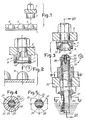
- la FIG. 1 représente un dispositif d'alimentation de parties supérieures de capsule avec un organe porteur équipé de moyens de support dans une position appropriée pour le prélèvement desdites parties de capsule;
- la FIG. 2 représente une vue en coupe longitudinale partielle des moyens de support de la partie supérieure de capsule;
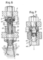
- la FIG. 3 représente le moyen de support de la partie supérieure de capsule en correspondance des moyens d'application du liquide;
- la FIG. 4 et 5 représentent des vues en coupe transversale suivant les lignes IV-IV- et V-V de la Fig. 3;
- la FIG. 6 représente une vue en coupe longitudinale suivant la ligne VI-VI de Fig. 3; et
- la FIG. 7 montre la phase de jonction des deux parties de capsule.
- FIG. 1 shows a device for feeding upper parts of the capsule with a carrier member equipped with support means in a position suitable for removing said parts of the capsule;
- FIG. 2 shows a view in partial longitudinal section of the means for supporting the upper part of the capsule;
- FIG. 3 shows the means for supporting the upper part of the capsule in correspondence with the means for applying the liquid;
- FIG. 4 and 5 show views in cross section along the lines IV-IV- and VV of FIG. 3;
- FIG. 6 shows a view in longitudinal section along the line VI-VI of FIG. 3; and
- FIG. 7 shows the junction phase of the two capsule parts.
Sur le dessin, le numéro de référence 1 indique un dispositif d'alimentation sur lequel se trouvent plusieurs capsules de fermeture ou partie supérieures S de capsule, provenant d'un récipient approprié. Chacune de ces parties S est prélevée par un moyen de support correspondant indiqué génériquement par 3 et représenté de manière plus détaillée sur la Fig. 2. En pratique, il est possible de prévoir un organe porteur 5, par exemple sous forme d'une barre s'étendant perpendiculairement au plan du dessin, sur lequel est appliquée une série de moyens de support 3. Avec un mouvement d'abaissement suivant le flèche f3 (Fig. 2), chaque moyen de support 3 est enfilé sur une partie supérieure S de capsule placée au-dessous. En pratique, il est possible de prévoir plusieurs dispositifs d'alimentation 1 en parallèle, de sorte qu'une seule course d'abaissement suivant f3 de l'organe porteur 5 permet de prélever un nombre de parties S de capsule correspondant au nombre de moyens de support 3. Inversément, on peut également prévoir que l'organe porteur 5 soit asservi à un mouvement d'alimentation intermittent suivant la direction perpendiculaire au dessin des Fig. 1 et 2, de manière qu'avec une combinaison de mouvements de soulèvement et d'abaissement et de translation en direction perpendiculaire à la figure, tous les moyens de supports 3 portés par l'organe porteur 5 puissent être chargés avec des parties S de capsule alimentées par un seul dispositif d'alimentation 1 en position fixe.In the drawing, the reference number 1 indicates a supply device on which there are several closure capsules or part upper capsule S, from a suitable container. Each of these parts S is removed by a corresponding support means indicated generically by 3 and shown in more detail in FIG. 2. In practice, it is possible to provide a
Comme on peut le voir en particulier sur la Fig. 2, le moyen de support 3 de la partie S de capsule comprend un organe cylindrique 7 formant une cavité 9 avec une gorge 11 dans laquelle est logé un joint 13 annulaire et de section circulaire. Lorsque le moyen de support 3 est enfilé sur la partie S de capsule, celle-ci pénètre dans la cavité 9 et elle est retenue avec une légère interférence par le joint 13 dans la position représentée sur la Fig. 3. Comme on peut le voir sur cette figure, la partie supérieure S de capsule présente un bord d'épaisseur inférieure, destiné à être enfilé sur un bord supérieur correspondant d'un corps de capsule montré en particulier sur la Fig. 7 et indiqué par C. Pour unir de manière stable la partie supérieure S et la partie inférieure C de la capsule, est prévue l'application d'un liquide approprié sur le bord B de la partie supérieure S de la capsule. Lorsque la capsule est réalisée en amidon, le liquide utilisé peut être de l'eau, ou encore une solution d'eau et d'alcool ou un liquide similaire, qui provoque un ramolissement ou une dissolution partielle de l'amidon dans la zone d'application. Lorsque le bord B de la partie S de capsule a été ainsi humidifié et donc partiellement dissous ou ramolli, il peut être enfilé sur le bord supérieur du corps de capsule C de telle manière que le séchage successif de l'amidon provoque la jonction des deux parties C et S et enferme de manière étanche le contenu P de la capsule.As can be seen in particular in FIG. 2, the support means 3 of the capsule part S comprises a
Pour appliquer le liquide de manière uniforme et dans la quantité correcte sur le bord B de la partie supérieure S de capsule, il est prévu selon l'invention un moyen d'application indiqué génériquement par 15 et montré en particulier sur les vues en coupe des Fig. 3, 4, 5 et 6. Le moyen 15 comprend une tige constituée par un axe central 17 et un organe cylindrique externe 19. L'axe 17 présente deux replats 21 diamétralement opposés qui forment, avec une chambre cylindrique 23 délimitée par l'organe cylindrique 19, deux sièges longitudinaux pour une bande de matière absorbante indiquée par 25. Comme on peut le voir en particulier sur la vue en coupe longitudinale de la Fig. 6, la bande 25 est disposée en U à l'intérieur des deux sièges 21 diamétralement opposés, alors que dans une section intermédiaire de ladite bande est prévu un trou, de sorte que la bande 25 peut être enfilée sur l'extrémité 29 de l'axe 17 présentant un diamètre réduit, afin d'être maintenue dans une position prédéterminée par rapport à l'axe 17. Dans l'extrémité 29 et dans une partie du corps de l'axe 17 est prévu un trou fileté dans lequel s'engage une vis 31 destinée à bloquer sur l'axe 17 un élément d'extrémité 33. Entre cet élément 33 et le corps de l'axe 17 est disposé un élément discoïde 35 en matière absorbante identique ou similaire à la matière de la bande 25, avec laquelle ledit élément discoïde est en contact direct. La vis 31 serre l'élément d'extrémité 33 sur la tige 17 de manière à maintenir l'élément discoïde 35 en contact étroit avec la bande 25 pour les buts indiqués par la suite. La longueur de l'extrémité 29 et l'épaisseur de la matière formant la bande 25 et l'élément discoïde 35 peuvent être calibrées de manière appropriée pour serrer avec la force désirée la matière absorbante et obtenir ainsi la distribution de la quantité correcte de liquide.
Le moyen d'application 15 est supporté par une traverse 37 qui peut porter une pluralité desdits moyens d'application 15 disposés sur une rangée ou sur plusieurs rangées, et dans tous les cas selon une disposition correspondant à la disposition des moyens de support 3 qui sont présentés au-dessus des moyens 15 et abaissés sur ceux-ci pour amener les parties supérieures S de capsule en contact avec les différents éléments discoïdes 33 disposés en correspondance des extrémités des différents moyens d'application 15 portés par la traverse 37. Au-dessous de la traverse 37 est prévu un récipient (non représenté) dans lequel est contenu le liquide L qui doit être appliqué uniformément sur le bord B des parties S de capsule. La bande 25 a une longueur telle que ses extrémités 25E soient toujours immergées dans le liquide L, lequel est prélevé par capillarité et remonte le long des deux branches de la bande 25 jusqu'à imprégner l'élément discoïde 35. Par conséquent, lorsqu'une partie supérieure S de capsule est enfilée sur l'élément discoïde 35 (qui dépasse de manière appropriée du profil externe de la tige formée par les organes 17, 19 et 33), sur le bord annulaire B de ladite partie S est distribuée uniformément une quantité de liquide L suffisante pour provoquer le ramollissement ou une dissolution partielle de la matière constituant la capsule. Lorsque le bord B de la partie de capsule s a été mouillé, l'organe porteur 5 avec les moyens de support 3 peut être soulevé et déplacé par translation jusqu'à arriver en correspondance d'un organe 40 qui présente une pluralité de sièges 42 dans lesquels sont logés les corps C des capsules qui doivent être fermées au moyen des parties supérieures S opportunément mouillées le long de leurs bords B. Les moyens de support 37 sont alors soulevés pour enfiler les parties S de capsule sur les corps de capsule C et premettre ainsi la fermeture des capsules elles-mêmes. Sur la Fig. 7 est représentée la phase de fermeture des capsules.
Après que la partie S a été insérée sur le corps C de la capsule, l'organe porteur 5 peut être soulevé suivant la flèche f5 à partir de la position de la fig. 7 pour dégager la partie S du siège 9. Le déboitement de la partie supérieure S de capsule hors du siège 9 peut être facilité au moyen d'un extracteur ou d'une surpression crèe dans ledit siège 9, en agissant à travers l'orifice placé au-dessus (Fig. 2). A ce stade, les différentes capsules sont fermées hermétiquement et prêtes pour être conditionnées. Elles sont extraites de l'organe 40 au moyen d'un extracteur approprié ou autre.
Il est évident que le dispositif selon l'invention peut être utilisé non seulement pour la fermeture de capsules en amidon qui nécessitent l'application de liquides solvants (tels que l'eau ou des mélanges d'eau et d'alcool ou similaires), mais également dans tous les autre cas dans lesquels, pour la fermeture de la capsule, est nécessaire l'application d'un liquide dont les propriétés physiques sont telles qu'elles permettent le prélèvement dans un réservoir par capillarité.
Selon un autre mode de réalisation modifié, on peut prévoir que la tige 17 avec l'embout 33, la bande absorbante 25 et l'élément discoïde 35 soit mobile verticalement à l'intérieur de l'organe cylindrique 19. De cette manière, l'élément discoïde 35 pourrait être comprimé de façon cyclique entre le bord supérieur de l'organe cylindrique 19 fixe et l'embout 33 mobile, à chaque opération d'application du liquide sur la partie supérieure S de la capsule. Le pressage de l'élément discoïde 35 entraîne la distribution d'une plus grande quantité de liquide.To apply the liquid evenly and in the correct amount to the edge B of the upper part S of the capsule, it is provided according to the invention an application means indicated generically by 15 and shown in particular in the sectional views of FIGS. 3, 4, 5 and 6. The
The application means 15 is supported by a
After the part S has been inserted on the body C of the capsule, the carrying
It is obvious that the device according to the invention can be used not only for closing starch capsules which require the application of solvent liquids (such as water or mixtures of water and alcohol or the like), but also in all other cases in which, for closing the capsule, it is necessary to apply a liquid whose physical properties are such that they allow withdrawal from a reservoir by capillary action.
According to another modified embodiment, provision may be made for the
Claims (8)
- Device for closing capsules in two parts (S, C) consisting of a means of support (3) for an upper part (S) of the capsule and means of application (15) on the said upper part (S) of the capsule of a liquid intended to cause reciprocal union between the said upper part (S) and the lower part (C) of the capsule, the said means of application (15) consisting of an absorbent organ (25, 35) intended to take the said liquid into a reservoir by capillary action and to distribute it on the said upper part (S) of the capsule (S, C) characterized in that the said organ consists of a rod (17, 19) corresponding to the upper end of which a disk part (35) of absorbent material projects, which is in contact with a linear part (25) of absorbent material extending along the said red (17, 19), the said disk element (35) being capable of being inserted in the said upper part of the capsule (S) so as to make contact only with its lower edge with the lower part (C) of the capsule.
- Device according to claim 1, characterized in that the said red consists of a central axis (17) fitted with longitudinal receptacles (21) for accommodating the said linear part and an external cylindrical closing organ (19).
- Device according to one or more of the preceding claims, characterized in that the said means of support (3) includes a cavity (9) fitted with an annular joint (13) to hold the upper part (S) of the capsule.
- Device according to one or more of the preceding claims, characterized in that it consists of a support organ (5) equipped with one or more menus of support (3) and provided to position itself in a first position to correspond with a feeding device (1) of the upper parts (S) of capsules, a second position corresponding to the corresponding means of application (15) of the liquid, and a third position corresponding to the corresponding support organs (40) of the lower parts (C) of the capsules.
- Device according to one or more of the preceding claims, characterized in that the said disk part is cyclically compressed to extract a predetermined quantity of liquid from the absorbent organ.
- Device according to one or more of claims 1 or 2, characterized in that the said rod (17, 19) has a part (17) movable axially to compress the said part (35) of absorbent material.
- Process to close the capsules in two parts (S, C) consisting of the phases of:- distribution to one part (S) of the two parts of the capsule of a liquid intended to cause reciprocal union of the two parts (S, C) of the capsule;- union of the two parts (S, C) of the capsule to cause their joining;the liquid being taken to a reservoir by capillary action via an absorbent organ, the said distribution of the liquid being provided by contact between the said part (S) of the capsule and the absorbent organ, a process characterized in that the extension of the said contact is limited solely at the internal edge (B) of the joint of the said part (S) with the second part (C) of the capsule, the said contact being made by means of a disk part (35) of absorbent material, making part of the said organ absorbent.
- Process according to claim 7, characterized in that the said disk part is cyclically compressed to extract a predetermined quantity of liquid from the absorbent organ.
Priority Applications (3)
| Application Number | Priority Date | Filing Date | Title |
|---|---|---|---|
| AT92830210T ATE126692T1 (en) | 1992-05-07 | 1992-05-07 | DEVICE FOR CLOSING TWO-PART CAPSULES. |
| EP92830210A EP0569656B1 (en) | 1992-05-07 | 1992-05-07 | Apparatus for the closure of two-part capsules |
| DE69204278T DE69204278D1 (en) | 1992-05-07 | 1992-05-07 | Device for closing two-part capsules. |
Applications Claiming Priority (1)
| Application Number | Priority Date | Filing Date | Title |
|---|---|---|---|
| EP92830210A EP0569656B1 (en) | 1992-05-07 | 1992-05-07 | Apparatus for the closure of two-part capsules |
Publications (2)
| Publication Number | Publication Date |
|---|---|
| EP0569656A1 EP0569656A1 (en) | 1993-11-18 |
| EP0569656B1 true EP0569656B1 (en) | 1995-08-23 |
Family
ID=8212099
Family Applications (1)
| Application Number | Title | Priority Date | Filing Date |
|---|---|---|---|
| EP92830210A Expired - Lifetime EP0569656B1 (en) | 1992-05-07 | 1992-05-07 | Apparatus for the closure of two-part capsules |
Country Status (3)
| Country | Link |
|---|---|
| EP (1) | EP0569656B1 (en) |
| AT (1) | ATE126692T1 (en) |
| DE (1) | DE69204278D1 (en) |
Families Citing this family (1)
| Publication number | Priority date | Publication date | Assignee | Title |
|---|---|---|---|---|
| EP0765150B1 (en) * | 1994-06-16 | 2002-09-11 | Warner-Lambert Company | Process and apparatus for producing closed sealed capsules |
Family Cites Families (2)
| Publication number | Priority date | Publication date | Assignee | Title |
|---|---|---|---|---|
| CH674800A5 (en) * | 1986-03-12 | 1990-07-31 | Warner Lambert Co | |
| IT1207675B (en) * | 1987-04-27 | 1989-05-25 | Mg 2 Spa | PHARMACEUTICAL MACHINE FOR WETTING A COVER TO BE FIXED ON A BOTTOM FILLED FOR EXAMPLE WITH A PRODUCT- |
-
1992
- 1992-05-07 AT AT92830210T patent/ATE126692T1/en active
- 1992-05-07 DE DE69204278T patent/DE69204278D1/en not_active Expired - Lifetime
- 1992-05-07 EP EP92830210A patent/EP0569656B1/en not_active Expired - Lifetime
Also Published As
| Publication number | Publication date |
|---|---|
| EP0569656A1 (en) | 1993-11-18 |
| DE69204278D1 (en) | 1995-09-28 |
| ATE126692T1 (en) | 1995-09-15 |
Similar Documents
| Publication | Publication Date | Title |
|---|---|---|
| CA2310116C (en) | Device for packaging a liquid to be dispensed drop by drop | |
| EP0509179B1 (en) | Method for the vacuum packaging of products, in particular cosmetic or pharmaceutical products, in containers with variable capacity, closed by a dispensing means without air exhaust | |
| CA2344214C (en) | Syringes for administering pasty or semi-solid formulations | |
| CA1308399C (en) | Viscous product dispensing container | |
| EP0728427A1 (en) | Applicator for cosmetic substances | |
| EP0382594B1 (en) | Piston-type dispenser for a pasty or solid substance | |
| EP0382591B1 (en) | Dispenser for pasty or solid products with a coated dispensing opening | |
| CH666870A5 (en) | DEVICE FOR PACKAGING LIQUID OR LIQUID AND SOLID SUBSTANCES. | |
| FR2991307A1 (en) | VISCOUS PRODUCT DISPENSER | |
| FR3095322A1 (en) | Cosmetic product container | |
| FR2668118A1 (en) | PROCESS FOR PACKAGING PASTY LIQUID PRODUCTS IN VACUUM DISPENSER, DEVICE FOR IMPLEMENTING THE SAME, AND DISPENSERS THUS OBTAINED | |
| FR3058874B1 (en) | COSMETIC REFILL FOR THE APPLICATION OF A CAPILLARY PRODUCT | |
| FR2745492A1 (en) | PACKAGING ASSEMBLY FOR LYOPHILIZED PREPARATIONS | |
| EP0569656B1 (en) | Apparatus for the closure of two-part capsules | |
| EP1893123B1 (en) | Method for packing a predetermined liquid substance dose in a straw and device for carrying out said method | |
| FR2615761A1 (en) | LIQUID APPLICATOR DEVICE | |
| EP1638855B1 (en) | Application device for liquid product | |
| FR2569560A1 (en) | Bag for packaging products for haemodialysis and device for producing the concentrate for haemodialysis | |
| FR2658739A1 (en) | DEVICE FOR DISPENSING LIQUID OR PASTY PRODUCT, ESPECIALLY COSMETIC PRODUCT. | |
| FR2727670A1 (en) | Dosing container for distributing liquid from reservoir, esp. used for cosmetic products | |
| CH631089A5 (en) | METHOD AND APPARATUS FOR DEPOSITING A LIQUID SAMPLE LAYER ON THE SURFACE OF A SUPPORTING LIQUID CONTAINED IN A SEMI-FIRM CENTRIFUGATION TUBE. | |
| FR2713059A1 (en) | Stopper for closing container and applying liquid | |
| FR2649377A1 (en) | PROCESS FOR PACKAGING AEROSOL GENERATOR PRODUCT IN A DISPENSER CONTAINER, MACHINE FOR CARRYING OUT SAID METHOD, AND CONTAINER OBTAINED BY SAID METHOD AND / OR MACHINE | |
| FR3140071A1 (en) | Fluid delivery device | |
| FR3104009A1 (en) | Process for filling a device for packaging and dispensing a cosmetic composition |
Legal Events
| Date | Code | Title | Description |
|---|---|---|---|
| PUAI | Public reference made under article 153(3) epc to a published international application that has entered the european phase |
Free format text: ORIGINAL CODE: 0009012 |
|
| 17P | Request for examination filed |
Effective date: 19930317 |
|
| AK | Designated contracting states |
Kind code of ref document: A1 Designated state(s): AT BE CH DE DK ES FR GB LI NL PT SE |
|
| 17Q | First examination report despatched |
Effective date: 19940930 |
|
| GRAA | (expected) grant |
Free format text: ORIGINAL CODE: 0009210 |
|
| AK | Designated contracting states |
Kind code of ref document: B1 Designated state(s): AT BE CH DE DK ES FR GB LI NL PT SE |
|
| PG25 | Lapsed in a contracting state [announced via postgrant information from national office to epo] |
Ref country code: NL Free format text: LAPSE BECAUSE OF FAILURE TO SUBMIT A TRANSLATION OF THE DESCRIPTION OR TO PAY THE FEE WITHIN THE PRESCRIBED TIME-LIMIT Effective date: 19950823 Ref country code: ES Free format text: THE PATENT HAS BEEN ANNULLED BY A DECISION OF A NATIONAL AUTHORITY Effective date: 19950823 Ref country code: DK Effective date: 19950823 Ref country code: AT Effective date: 19950823 |
|
| REF | Corresponds to: |
Ref document number: 126692 Country of ref document: AT Date of ref document: 19950915 Kind code of ref document: T |
|
| REF | Corresponds to: |
Ref document number: 69204278 Country of ref document: DE Date of ref document: 19950928 |
|
| PG25 | Lapsed in a contracting state [announced via postgrant information from national office to epo] |
Ref country code: SE Effective date: 19951123 Ref country code: PT Effective date: 19951123 |
|
| PG25 | Lapsed in a contracting state [announced via postgrant information from national office to epo] |
Ref country code: DE Effective date: 19951124 |
|
| GBT | Gb: translation of ep patent filed (gb section 77(6)(a)/1977) |
Effective date: 19951120 |
|
| NLV1 | Nl: lapsed or annulled due to failure to fulfill the requirements of art. 29p and 29m of the patents act | ||
| PGFP | Annual fee paid to national office [announced via postgrant information from national office to epo] |
Ref country code: FR Payment date: 19960328 Year of fee payment: 5 |
|
| PGFP | Annual fee paid to national office [announced via postgrant information from national office to epo] |
Ref country code: GB Payment date: 19960404 Year of fee payment: 5 |
|
| PGFP | Annual fee paid to national office [announced via postgrant information from national office to epo] |
Ref country code: BE Payment date: 19960510 Year of fee payment: 5 |
|
| PG25 | Lapsed in a contracting state [announced via postgrant information from national office to epo] |
Ref country code: LI Effective date: 19960531 Ref country code: CH Effective date: 19960531 |
|
| PLBE | No opposition filed within time limit |
Free format text: ORIGINAL CODE: 0009261 |
|
| STAA | Information on the status of an ep patent application or granted ep patent |
Free format text: STATUS: NO OPPOSITION FILED WITHIN TIME LIMIT |
|
| 26N | No opposition filed | ||
| REG | Reference to a national code |
Ref country code: CH Ref legal event code: PL |
|
| PG25 | Lapsed in a contracting state [announced via postgrant information from national office to epo] |
Ref country code: GB Effective date: 19970507 |
|
| PG25 | Lapsed in a contracting state [announced via postgrant information from national office to epo] |
Ref country code: BE Effective date: 19970531 |
|
| BERE | Be: lapsed |
Owner name: SENESI ROBERTO Effective date: 19970531 |
|
| GBPC | Gb: european patent ceased through non-payment of renewal fee |
Effective date: 19970507 |
|
| PG25 | Lapsed in a contracting state [announced via postgrant information from national office to epo] |
Ref country code: FR Free format text: LAPSE BECAUSE OF NON-PAYMENT OF DUE FEES Effective date: 19980130 |
|
| REG | Reference to a national code |
Ref country code: FR Ref legal event code: ST |