EP0567801A2 - Universal phase match path generator for three-phase power - Google Patents
Universal phase match path generator for three-phase power Download PDFInfo
- Publication number
- EP0567801A2 EP0567801A2 EP93105503A EP93105503A EP0567801A2 EP 0567801 A2 EP0567801 A2 EP 0567801A2 EP 93105503 A EP93105503 A EP 93105503A EP 93105503 A EP93105503 A EP 93105503A EP 0567801 A2 EP0567801 A2 EP 0567801A2
- Authority
- EP
- European Patent Office
- Prior art keywords
- load
- phase
- source
- new
- rotation
- Prior art date
- Legal status (The legal status is an assumption and is not a legal conclusion. Google has not performed a legal analysis and makes no representation as to the accuracy of the status listed.)
- Withdrawn
Links
Images


Classifications
-
- H—ELECTRICITY
- H02—GENERATION; CONVERSION OR DISTRIBUTION OF ELECTRIC POWER
- H02J—ELECTRIC POWER NETWORKS; CIRCUIT ARRANGEMENTS OR SYSTEMS FOR SUPPLYING OR DISTRIBUTING ELECTRIC POWER; SYSTEMS FOR STORING ELECTRIC ENERGY
- H02J3/00—Circuit arrangements for AC mains or AC distribution networks
- H02J3/38—Arrangements for feeding a single network from two or more generators or sources in parallel; Arrangements for feeding already energised networks from additional generators or sources in parallel
- H02J3/40—Synchronisation of generators for connection to a network or to another generator
- H02J3/44—Synchronisation of generators for connection to a network or to another generator with means for ensuring correct phase sequence
Definitions
- the invention disclosed broadly relates to the switching of multi-phase electrical power sources, and more particularly, relates to the precise matching of the relative phases in a multi-phase system for switching between two power sources and a load which may be rotating either clockwise or counterclockwise with respect to each other or to the load.
- the invention as claimed allows for the removal of restrictions on the rotation directions of power sources of poly-phase power supplies being connected to the load. According to the claims this is accomplished by having two control signals derived from the configuration of the power system, one of which indicates the desired rotation direction of the load and the second one indicates to a controller the device which is being monitored to provide a timing reference for the electrical signal selection.
- the invention allows for the removal of restrictions on the rotation direction of the sources or the load and allows for the timing reference to be derived from the new source as well as from the present source or the load.
- the definition of three additional paths for connecting the source to the load allows any source to be rotating in the opposite direction from the desired load rotation without requiring this to be a fatal system error as in Ross et al.
- control signals which are derived from the configuration of the power system. These control signals may be provided by an external controller, by dedicated circuitry, or may be hardwired to set values if the system configuration will not be changed.
- the control signals are (1) an indication of the desired rotation direction of the load, either ABC or ACB; (2) an indication of which device is being monitored for the timing reference (a new source, present source, or load).
- the new path is also represented as a 1-of-6 selection, using a minimum of 3 select signals.
- the minimum size of the new path PROM is 256 by 3 when the load and new source polarities (minimum 3 bits each) are used as inputs, and 2048 (2K) by 3 when the present and new source polarities and the present path (minimum 3 bits) are used as inputs.
- the new path PROM processes 2 new inputs from the new source rotation detector; therefore, the minimum number of PROM inputs required for the load and new source implementation is 8 and the minimum number required for the two source and present path implementation is 11. These two configurations are shown in Tables II and III.
- the output register for the new path PROM is 3 bits wide.
- This invention also includes a new source rotation detector, consisting of the circuit elements shown in Fig. 14.
- the new source rotation detector is discussed later.
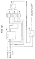
- the internal circuitry of the polarity change detector, shown in Fig. 13, is the same as previously disclosed in Gaddis et al.; the only difference is that the new source polarities may be used as inputs to this circuit, subject to the requirements which are discussed later.
- the invention uses a timing reference derived from the position of one of the power system devices as the reference for determining the closest phase alignment of the new source to the phase position of the load.
- the phase match path generator outputs a set of signals defined as the "New Path" which indicates the best method for connecting the phases of the new source to the phases of the load to achieve a transfer of power between sources with a desired minimal disturbance to the load.
- the output of the detection circuit is synchronized with the changes of position of the reference device, that is, the device used for timing. Digital values are used as a representation of the present source, new source and load polarities and the clock. Implementation of the invention uses a polarity change detector, new path PROM and PROM output register, with the latching of the new path PROM outputs into the PROM output register synchronized to the output of the polarity change detector.
- a 3 phase waveform can be represented by 6 distinct states of 60 electrical degrees each.
- a state transition occurs when one of the three phases crosses zero volts, either going from a positive to a negative voltage or from a negative to a positive voltage. If a positive voltage is represented by a logical "1" and a negative voltage is represented by a logical "0", then for a complete 360 degree rotation, each phase will consist of three states where the voltage is positive and three states with a voltage negative; i.e. 3 logical "1"s and 3 logical "0"s.
- the polarities of a three phase source may be represented as follows for the specific rotation direction of the source (or load), either ABC or ACB: Ang. Position (Phase A) Rotation Dir.
- Reversed phase wiring is not an uncommon problem in power systems. Repairing reversed phases usually involves removing the faulty device from the system, disassembling it, correcting the wiring, reassembling the device and restoring the device to the system.
- Path 4 connects source phase A to load phase A, source B to load C and source C to load B.
- Path 5 connects source A to load C, source B to load B and source C load to load A.
- Path 6 connects source A to load B, source B to load A and source C to load C.
- the selected new path allows the phase of a new source which is nearest to a reference load phase to be connected to that reference phase, with the remaining two source to load phase connections defined by the new path.
- Figs. 2 and 3 show which new path needs to be selected for a transfer to occur with no more than a 60 degree phase displacement at the load. To use Figs. 2 and 3, choose a reference phase of the new source or load at the time a transfer is to be initiated, then identify the nearest phase of the opposite device (load or new source) at that time. The intersection of the row and column selected yields the new path to connect the new source to the load.
- Fig. 2 is used for systems where the new source and the load are rotating in the same direction.
- a variation of the implementation for this invention allows the present source and new source polarities to be monitored by the new path PROM.
- This implementation requires that the present path from the present source to the load also be provided to the new path PROM, as shown in Fig. 12.
- Fig. 4 can be used to find the appropriate load phase to use with Figs. 2 and 3 for calculating the new path. In Fig. 4 the intersection of a present source phase selected and a present path yields the load phase which needs to be used in Figs. 2 and 3.
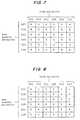
- Figs. 5, 6, 7 and 8 are new path selection matrices which are implemented in the new path PROM.
- the "inputs" to these figures are the polarities of the load and new source; the “output” is the new path.
- the six valid polarity states are listed for each row and column (states 000 and 111 are not valid). These figures calculate the new path based on the angular position of the new source and load at a particular time.
- Figs. 5 and 6 are used when a new source and load are rotating in the same direction.
- the polarities in Figs. 5 and 6 are listed in ABC order where: 0 denotes phase voltage is less than or equal to zero and 1 denotes phase voltage is greater than or equal to zero. Figs.
- the device which detects changes in source or load polarity is shown in Fig. 13.
- Input polarities may be from load or new source if load and new source polarities are used to generate the new path, OR from present source or new source if source polarities and the present path are used to generate the new path.
- the polarity change detector contains a 3 bit polarity history register 160, three exclusive OR polarity compare gates 162, 164 and 166, a change compare OR gate 168 and synchronizing register 161.
- the polarity history register is used to store previous sample polarity data for comparison.
- the polarity compare gates detect a change in polarity for each phase.
- the change compare gate combines the detected polarity change into a single data bit.
- the synchronizing register is used to align the polarity change data with the clock, and holds the change bit active for one clock cycle.
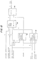
- the device which generates a new source path selection from present and new source polarities and the present path is shown in Fig. 12.
- the path generator contains a polarity change detector 150, a new source rotation detector 152, a 2048x3 new path PROM 154, and a new path register 156.
- the polarity change detector 150 is shown in Fig. 13.
- the new source rotation detector 152 is shown in Fig. 14.
- the new path PROM 154 calculates the new path from the present path, present source polarities and new source polarities as shown in the matrices in Figs. 5-8.
- the new path register 156 synchronizes the new path to the output of the polarity change detector.
- the polarity change detector can operate with either the present source polarities or the new source polarities.
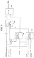
- the device which generates a new source path selection from load and new source polarities is shown in Fig. 11.
- the path generator contains a polarity change detector 140, a new source rotation detector 142, a 256x3 new path PROM 144, and a new path register 146.
- the polarity change detector 140 is shown in Fig. 13.
- the new source rotation detector 142 is shown in Fig. 14.
- the new path PROM 144 calculates the new path from the load polarities and the new source polarities as shown in the matrices in Figs. 5-8.
- the new path register 146 synchronizes the new path to the output of the polarity change detector.
- the polarity change detector can operate with either the load polarities or the new source polarities.
- the four selection matrices are different, and apply to different system configurations.
- the device which selects the proper selection matrix based on an analysis of the system configuration is the new source rotation detector, shown in Fig. 14.
- the new source rotation detector contains a 3 bit polarity history register 170, a 128 x 2 PROM 172, a 1 bit rotation history register 174, and 2 exclusive OR gates 176 and 178.
- the rotation PROM analyzes the rotation history (the known rotation direction from the previous clock cycle), the real-time new source polarities (prior to the next clock cycle) and the new source polarity history (from the previous clock cycle).
- the rotation PROM checks the real-time polarities of a new source and compares them to the polarities from the previous clock cycle. If the value matches, then the known rotation direction is maintained. If the values do not match, then the PROM checks to make sure the real-time polarity is allowable in accordance with the polarity sequence for the known rotation direction. If the sequence is allowable, the rotation direction is maintained. If the sequence is not allowable, a "rotation error" is detected and an output signal set for processing by system maintenance circuitry.
- Load rotation and “timing reference select” are system configuration values where: a) load rotation is defined to be “0” when load is rotating in ABC direction and “1” when rotating in ACB direction. b) timing reference is defined to be “0” when the new source is the input to the polarity change detector and “1” when the present source or load is the input to the polarity change detector.
- the exclusive OR gates 176 and 178 produce the select lines for the matrices which are implemented in the new path PROM and which are shown in Figs. 5-8.
- the first exclusive OR gate 176 operates on the "load rotation" configuration value and the output of the new source rotation history register 174. The output of this gate is logically true when the rotation of the new source is the opposite of the rotation of the load. The output signal is called “reverse” and is connected to an input of the new path PROM.
- the second exclusive OR gate 178 operates on the "timing reference select" configuration value and the "load rotation” configuration value. For example, suppose that the timing reference configuration is defined to be logically active when the present source or load is used as a timing reference and logically inactive when the new source is used as a timing reference, and the load rotation configuration is defined to be logically active when a load rotation is ACB and logically inactive when a load rotation is ABC. The output of the exclusive OR gate then is logically true when the load has ACB rotation AND the timing reference is the present source or load or the load has ABC rotation and the new source is the timing reference. This output signal is called "solution select" and is connected to an input of a new path PROM.
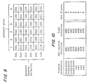
- Fig. 10 summarizes the function of the new source rotation detector.
- the inputs are the timing reference, the new source rotation and the desired load rotation.
- the output identifies the correct solution matrix to use (Figs. 5-8) for the given system configuration.
- the PROM code listings for the 256 x 3 new path PROM, the 2K x 3 new path PROM and the 128 x 2 rotation PROM are shown in Tables I, II, and III.
- the PROMs implement the functions identified above and shown in the figures.
- the PROM code is dependent upon implementation, but does not alter the principles of the invention. Logical "0" or “1” assignments ⁇ were chosen for convenience of use.
- "X" in the rotation PROM listing means the output value can be either "1" or "O". In these situations, it is assumed that the rotation error signal will be processed, which would indicate that there is a flaw in the hardware that generates the polarity signals.
- a present path of 00 is interpreted to be when the load is off (no current is being provided to load). This would be a start up state.
- the new path is assumed to be: Number 1 if valid polarities are present and “reverse” is logically inactive or Number 4 if valid polarities are present and "reverse" is logically active.
- Polarity values of 000 or 111 are considered to be invalid.
Landscapes
- Engineering & Computer Science (AREA)
- Power Engineering (AREA)
- Supply And Distribution Of Alternating Current (AREA)
- Control Of Electric Motors In General (AREA)
- Control Of Ac Motors In General (AREA)
Applications Claiming Priority (2)
| Application Number | Priority Date | Filing Date | Title |
|---|---|---|---|
| US87666892A | 1992-04-03 | 1992-04-03 | |
| US876668 | 1992-04-30 |
Publications (2)
| Publication Number | Publication Date |
|---|---|
| EP0567801A2 true EP0567801A2 (en) | 1993-11-03 |
| EP0567801A3 EP0567801A3 (enExample) | 1994-03-23 |
Family
ID=25368325
Family Applications (1)
| Application Number | Title | Priority Date | Filing Date |
|---|---|---|---|
| EP93105503A Withdrawn EP0567801A2 (en) | 1992-04-30 | 1993-04-02 | Universal phase match path generator for three-phase power |
Country Status (3)
| Country | Link |
|---|---|
| US (1) | US5311066A (enExample) |
| EP (1) | EP0567801A2 (enExample) |
| JP (1) | JP2654329B2 (enExample) |
Cited By (3)
| Publication number | Priority date | Publication date | Assignee | Title |
|---|---|---|---|---|
| WO2014053989A3 (en) * | 2012-10-01 | 2014-06-12 | Abb Technology Ltd. | A method and a system for a fast bus transfer in an electrical power system |
| WO2017032996A1 (en) * | 2015-08-21 | 2017-03-02 | Mc Power Innovations Ltd | Switch, distributor system and method of adjusting current imbalance or phase to neutral voltages |
| CN115275975A (zh) * | 2022-06-24 | 2022-11-01 | 国网湖北省电力有限公司襄阳供电公司 | 一种光储充电站电力数据匹配度的确定方法及装置 |
Families Citing this family (6)
| Publication number | Priority date | Publication date | Assignee | Title |
|---|---|---|---|---|
| US5784240A (en) * | 1996-12-20 | 1998-07-21 | Automatic Switch Company | Method and apparatus for limiting current surge upon transfer of a load between A.C. power sources |
| US7129599B2 (en) * | 2002-10-15 | 2006-10-31 | Soft Switching Technologies Corporation | Dual feed power supply systems with enhanced power quality |
| US7589438B2 (en) * | 2004-07-09 | 2009-09-15 | Layerzero Power Systems, Inc. | Source phase sensitive transfer method and apparatus |
| SE541282C3 (en) * | 2017-09-05 | 2019-07-16 | Husqvarna Ab | Separator and method of operating a separator |
| SE541077C2 (en) * | 2017-09-05 | 2019-03-26 | Husqvarna Ab | Separator, separator system and methods of their operation |
| US10608438B2 (en) * | 2018-04-17 | 2020-03-31 | The Boeing Company | Electrical power generation system and method for aircraft |
Family Cites Families (7)
| Publication number | Priority date | Publication date | Assignee | Title |
|---|---|---|---|---|
| US4021704A (en) * | 1976-02-27 | 1977-05-03 | Borg-Warner Corporation | Phase sequence correcting system for three-phase AC power |
| JPS6034744U (ja) * | 1983-08-16 | 1985-03-09 | 株式会社荏原製作所 | 水中モ−タポンプ |
| JPS61142919A (ja) * | 1984-12-12 | 1986-06-30 | カワソーテクセル株式会社 | 低圧無停電切替装置 |
| US4761563A (en) * | 1987-10-27 | 1988-08-02 | International Business Machines Corporation | Asynchronous multiphase switching gear |
| US4937462A (en) * | 1989-01-23 | 1990-06-26 | Sundstrand Corporation | No break power transfer control for a VSCF power generating system |
| US5212407A (en) | 1990-10-04 | 1993-05-18 | International Business Machines Corporation | Digital phase match discriminator for three-phase power |
| US5182464A (en) * | 1991-01-09 | 1993-01-26 | Techmatics, Inc. | High speed transfer switch |
-
1993
- 1993-03-29 JP JP7011393A patent/JP2654329B2/ja not_active Expired - Lifetime
- 1993-04-02 EP EP93105503A patent/EP0567801A2/en not_active Withdrawn
- 1993-08-13 US US08/106,324 patent/US5311066A/en not_active Expired - Lifetime
Cited By (7)
| Publication number | Priority date | Publication date | Assignee | Title |
|---|---|---|---|---|
| WO2014053989A3 (en) * | 2012-10-01 | 2014-06-12 | Abb Technology Ltd. | A method and a system for a fast bus transfer in an electrical power system |
| CN104813558A (zh) * | 2012-10-01 | 2015-07-29 | Abb技术有限公司 | 用于电力系统中的快速总线转换的方法和系统 |
| US9923375B2 (en) | 2012-10-01 | 2018-03-20 | Abb Schweiz Ag | Method and a system for a fast bus transfer in an electrical power system |
| CN104813558B (zh) * | 2012-10-01 | 2018-10-23 | Abb瑞士股份有限公司 | 用于电力系统中的快速总线转换的方法和系统 |
| WO2017032996A1 (en) * | 2015-08-21 | 2017-03-02 | Mc Power Innovations Ltd | Switch, distributor system and method of adjusting current imbalance or phase to neutral voltages |
| CN115275975A (zh) * | 2022-06-24 | 2022-11-01 | 国网湖北省电力有限公司襄阳供电公司 | 一种光储充电站电力数据匹配度的确定方法及装置 |
| CN115275975B (zh) * | 2022-06-24 | 2024-02-20 | 国网湖北省电力有限公司襄阳供电公司 | 一种光储充电站电力数据匹配度的确定方法及装置 |
Also Published As
| Publication number | Publication date |
|---|---|
| JPH0686465A (ja) | 1994-03-25 |
| EP0567801A3 (enExample) | 1994-03-23 |
| JP2654329B2 (ja) | 1997-09-17 |
| US5311066A (en) | 1994-05-10 |
Similar Documents
| Publication | Publication Date | Title |
|---|---|---|
| EP0567801A2 (en) | Universal phase match path generator for three-phase power | |
| JPH082154B2 (ja) | 非同期多相スイツチング回路 | |
| JP2001327173A (ja) | モータ制御用pwmインバータ | |
| JPH11175490A (ja) | 縮退制御方法、多重化制御装置 | |
| US3416054A (en) | Motor control apparatus including sequential interval generating means for alternately enabling motor rotation in forward and reverse directions | |
| US5210443A (en) | Process and apparatus for parallel control of tapped transformers | |
| US5568034A (en) | Fault-tolerant variable speed induction motor drive | |
| US6693404B2 (en) | AC current detecting device for inverter apparatus and AC current detecting method therefor | |
| EP3767821A1 (en) | Fault-tolerant electrical drive | |
| US5959858A (en) | Electric power conversion apparatus | |
| US4329652A (en) | Apparatus for synchronization control of a plurality of inverters | |
| CN108199627A (zh) | 一种分布式电机驱动控制系统 | |
| EP0478966B1 (en) | Digital phase match discriminator for three-phase power | |
| EP1087563B1 (en) | System and method for reliably switching between redundant clocks | |
| JP3268181B2 (ja) | インバータの並列運転装置 | |
| RU2037264C1 (ru) | Устройство для обнаружения отказов в шаговом электроприводе | |
| JP2540177B2 (ja) | サ―ボモ―タの信号伝送装置 | |
| US4835451A (en) | Switching circuit for five-phase stepping motor and method of switching | |
| JP2540176B2 (ja) | サ―ボモ―タの信号伝送装置 | |
| de Lillo et al. | A power converter for fault tolerant machine development in aerospace applications | |
| JPH07274581A (ja) | ブラシレスモータの駆動回路 | |
| KR950000800B1 (ko) | 무브러시 모우터의 운전방법 및 운전장치 | |
| EP0348368B1 (en) | Method and apparatus for generating a start signal for parallel-synchronous operation of three identical data processing units | |
| EP3872983A1 (en) | Redundancy concept for the control of multi-lane electrical powertrain | |
| JP2571007B2 (ja) | バイポーラ信号切換器 |
Legal Events
| Date | Code | Title | Description |
|---|---|---|---|
| PUAI | Public reference made under article 153(3) epc to a published international application that has entered the european phase |
Free format text: ORIGINAL CODE: 0009012 |
|
| AK | Designated contracting states |
Kind code of ref document: A2 Designated state(s): DE FR GB |
|
| PUAL | Search report despatched |
Free format text: ORIGINAL CODE: 0009013 |
|
| 17P | Request for examination filed |
Effective date: 19931227 |
|
| AK | Designated contracting states |
Kind code of ref document: A3 Designated state(s): DE FR GB |
|
| 17Q | First examination report despatched |
Effective date: 19950123 |
|
| 18D | Application deemed to be withdrawn |
Effective date: 19960410 |