EP0566184A2 - Transformateur d'image ainsi que système de télévision comportant un émetteur et un récepteur munis d'un transformateur - Google Patents
Transformateur d'image ainsi que système de télévision comportant un émetteur et un récepteur munis d'un transformateur Download PDFInfo
- Publication number
- EP0566184A2 EP0566184A2 EP93200999A EP93200999A EP0566184A2 EP 0566184 A2 EP0566184 A2 EP 0566184A2 EP 93200999 A EP93200999 A EP 93200999A EP 93200999 A EP93200999 A EP 93200999A EP 0566184 A2 EP0566184 A2 EP 0566184A2
- Authority
- EP
- European Patent Office
- Prior art keywords
- transformer
- series
- picture
- block
- dimensional
- Prior art date
- Legal status (The legal status is an assumption and is not a legal conclusion. Google has not performed a legal analysis and makes no representation as to the accuracy of the status listed.)
- Withdrawn
Links
Images


Classifications
-
- H—ELECTRICITY
- H04—ELECTRIC COMMUNICATION TECHNIQUE
- H04N—PICTORIAL COMMUNICATION, e.g. TELEVISION
- H04N19/00—Methods or arrangements for coding, decoding, compressing or decompressing digital video signals
- H04N19/60—Methods or arrangements for coding, decoding, compressing or decompressing digital video signals using transform coding
-
- G—PHYSICS
- G06—COMPUTING; CALCULATING OR COUNTING
- G06F—ELECTRIC DIGITAL DATA PROCESSING
- G06F17/00—Digital computing or data processing equipment or methods, specially adapted for specific functions
- G06F17/10—Complex mathematical operations
- G06F17/14—Fourier, Walsh or analogous domain transformations, e.g. Laplace, Hilbert, Karhunen-Loeve, transforms
- G06F17/147—Discrete orthonormal transforms, e.g. discrete cosine transform, discrete sine transform, and variations therefrom, e.g. modified discrete cosine transform, integer transforms approximating the discrete cosine transform
Definitions
- the invention relates to a picture transformer for transforming a 2-dimensional block of input words into a 2-dimensional block of output words.
- the invention also relates to a television transmission system for television signals in which such a picture transformer is used and to the transmitter and the receiver of such a television transmission system.
- DCT Discrete Cosine Transform
- iDCT inverse form
- the 2-dimensional picture transform can be split up into two separate 1-dimensional transforms which are performed consecutively.
- transform each row of pixels is converted in a first transform into what will be referred to as a row of product elements.
- the product elements which have been obtained row by row are subsequently subjected in columns to a second transform and converted into coefficients.
- iDCT inverse transform
- each column of coefficients is converted in a corresponding manner in a first transform into a column of product elements whereafter each row of product elements is converted into a row of pixels in a second transform.
- the transform of rows is referred to as “horizontal transform” and the transform of columns is referred to as "vertical transform”.
- a picture transformer of the type described in the opening paragraph is known from European Patent Application EP-A 0 424 119.
- This known picture transformer comprises a 1-dimensional transformer which first transforms all rows of pixels of a block and stores the series of product elements obtained therefrom in a transposition memory (horizontal transform). Subsequently, all transposed series of product elements of said block are applied to the same 1-dimensional transformer for computing the coefficients (vertical transform). The vertical transform cannot start until the horizontal transform has been performed completely, i.e. for all rows.
- the picture transformer is characterized in that it comprises a multiplexer for alternately selecting a series of input words of a block and a transposed series of product elements of a previous block and for applying said series to the 1-dimensional transformer.
- a particularly favourable embodiment of the picture transformer is characterized in that it comprises means for applying the selected series in a parallel form to the 1-dimensional transformer. As soon as a row of pixels of a block is available in a parallel form, this row is horizontally transformed and a column of product elements is vertically transformed. During the time when these transforms are being performed, the application of the next row of pixels can be continued. This is effected at the normal sample frequency so that higher rates do not occur anywhere.
- Each product element, each coefficient (DCT) and each pixel (iDCT) is constituted by a linear combination of 8 elements from the series applied to the 1-dimensional transformer.
- Various computing schemes are known from literature, in which the number of multiplications (theoretically 8 per product element, i.e. 64 per row) is reduced to an acceptable number, for example 16 per row.
- Such a computing scheme also referred to as "DCT butterfly" indicates that (i) pixels are arranged in groups by means of adding and subtracting operations, (ii) the groups are subjected to multiplication operations and (iii) the multiplication results are combined by addition and subtraction.
- An attractive example of such a computing scheme is described, for example in European Patent Specification EP 0 286 183.
- the 1-dimensional transformer is of a type which, for the applied selected series, simultaneously computes a plurality of predetermined linear combinations of elements of this series.
- Such a simultaneous computation is many times faster than the successive computations which are used in practice and in which the pixels are successively grouped, stored and applied to a multiplier.
- This multiplier always receives a different multiplication factor ("butterfly coefficient").
- the successive computation seems to have the advantage that the number of hardware-implemented multipliers is limited.
- Such a transformer has, however, many registers for storing interim results of additions and subtractions. Said registers require a large chip surface but also much power dissipation because the dissipation of a chip is mainly determined by the number of registers. Moreover, a fast multiplier also dissipates much power.
- the multipliers for computing the linear combinations are preferably constituted by combinatory circuits which multiply an applied number by a predetermined fixed factor. For each fixed multiplication factor the corresponding multiplier can be optimized in such a way that it occupies a minimal chip surface. It has been found that the simultaneous computation of the product elements by means of said fixed multipliers is fast, yields a smaller chip surface and dissipates less power.
- a further embodiment of the picture transformer is characterized in that it receives a motion signal which is indicative of motion in the received block, while two predetermined portions of a series are consecutively applied to the 1-dimensional transformer in response to a predetermined value of said motion signal.
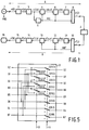
- Fig. 1 shows diagrammatically a television system in which a picture transformer according to the invention is used.
- the television system comprises a coding circuit A and a decoding circuit B which are coupled together by means of a transmission channel C.
- the transmission channel may be a wireless or wired connection. However, it may alternatively be a magnetic or optical storage medium.
- the coding circuit A may form part of a television transmitter and the decoding circuit B may form part of a television receiver.
- the television system may be in the form of a video recorder or a camera recorder. In that case the coding circuit A and the decoding circuit B are both accommodated in one apparatus.
- the coding circuit A receives a television picture signal x(t) from a picture signal source 1.
- the analog picture signal x(t) is sampled at a sample frequency fs and converted into 8-bit pixels x(n). These pixels are applied to a picture memory 3.
- the pixels are read from this picture memory in the form of blocks of, for example 8*8 pixels x(i,k) and applied to a first picture transformer 4 and to a motion detector 5.
- the motion detector 5 is known per se and may be implemented in a way as described in European Patent Application EP-A 0 282 135. It generates a motion signal MD if motion has been detected within the block of 8*8 pixels.
- picture transformer 4 is adapted to perform a Discrete Cosine Transform (DCT). For each presented block of pixels the transformer generates a block of 8*8 coefficients y(u,v). An embodiment of this picture transformer will be described in detail. In this respect it is to be noted that the picture transformer may operate in a motion-adaptive way. To this end the picture transformer receives the motion signal MD. The block of coefficients y(u,v) of the picture transformer 4 is subsequently applied to a scanner 6 which also receives the motion signal MD. The scanner supplies for each block a serial sequence of coefficients y(n) to a variable-length coder 7. The scanner 6 and the variable-length coder 7 are known per se.
- DCT Discrete Cosine Transform
- variable-length coder 7 codes each series of coefficients y(n) into code series of variable lengths which comprise a considerably smaller number of bits than the corresponding block of 8*8 coefficients y(u,v).
- the code series and the motion signal MD are transmitted in time-division multiplex format in the form of a pulse series z(j) by means of a multiplexer 8.
- the inverse operations are carried out in the decoding circuit B.
- a demultiplexer 10 the code series and the motion signal MD' are regained from the received pulse series z'(j).
- the code series are applied to a variable-length decoder 11 for reconstructing the serial sequences of coefficients y'(n).
- a block-formation circuit 12 receives the serial sequences as well as the motion signal MD' and forms the blocks of 8*8 coefficients y'(i,k) therefrom.
- the coefficients are applied to a second picture transformer 13. This transformer performs the inverse Discrete Cosine Transform (iDCT) so that each block of coefficients is retransformed into a block of 8*8 pixels x'(i,k).
- the blocks of pixels thus obtained are stored in a picture memory 14.
- the pixels in the picture memory jointly constitute a complete picture which is converted by means of a D/A converter 15 into an analog picture signal x'(t) for display on a display screen 16.
- Fig. 2 shows an embodiment of the picture transformer 4 which forms part of the coding circuit A.
- the pixels x(i,k) of a block are presented row by row and applied to a series-parallel converter 20.
- the series-parallel converter receives control signals t1 from a control circuit 26.
- the control signals are chosen in such a way that the 8 pixels x(i,0) .... x(i,7) of a row i are simultaneously available.
- the row of pixels is applied in a parallel form to a first input of a multiplexer 21.
- a second input of this multiplexer receives a column of 8 product elements, also in a parallel form, from a transposition memory 24.
- the selector In response to a selection signal t2 the selector either applies the row of pixels or the column of product elements to a shuffle network 22.
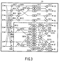
- Fig. 3 shows an embodiment of the 1-dimensional transformer for the case where it is adapted to perform a Discrete Cosine Transform (DCT). It comprises a plurality of adders and subtracters 30(i) which combine the 8 elements I0 ... I7 of an applied series in a predetermined manner. Combinations of the elements I thus formed are applied to multipliers 31(i) which multiply the applied number by a fixed predetermined factor. In the Figure this factor is indicated for each multiplier. The product values obtained are grouped in further adders and subtracters 32(i) in order to form 8 output elements O0 ... O7. Each output element has a value which is a linear combination of all input values.
- DCT Discrete Cosine Transform
- the output elements O(0) ... O(7) of the 1-dimensional transformer 23 are applied to a transposition memory 24 and to a parallel-series converter 25.
- the parallel-series converter 25 receives control signals t5 so as to convert the simultaneously presented output elements into a serial format at the sample frequency fs.
- the transposition memory 24 comprises a first memory 241 and a second memory 242 and receives write addresses WA1 and WA2, respectively, so as to store the output elements.
- the transposition memory receives read addresses RA1 and RA2, respectively, so as to apply previously stored output elements to the second input of the multiplexer 21.
- the various control signals, write addresses and read addresses are generated by the control circuit 26. To this end, this circuit receives the sample frequency fs, the motion signal MD and a frame reset pulse FRS. The frame reset pulse is received from the picture signal source 1 (see Fig. 1).
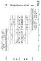
- Fig. 4 shows, in the form of a time diagram, various signals which occur in the picture transformer 4.
- the successive pixels x(i,k) of a row i of a presented block of pixels are indicated under A. More particularly, the Figure shows under A successively the last row of pixels x(7,0) ... x(7,7) of a block N (during a period of time T1) and the first row of pixels x(0,0) ... x(0,7) of the subsequent block N+1 (during a period of time T2).
- the output signal of the series-parallel converter 20 is indicated under B.
- the multiplexer selects the row of pixels r(7) and applies this row to the transformer 23.
- the Figure indicates under F that the (horizontal) transform of this row r(7) is effected during this period of time.
- the write address WA1 for addressing a row of this memory is applied to the first memory 241.
- the Figure indicates under G that the write address has the value R7, which means that the result of the horizontal transform is stored in row 7 of the first memory 241.
- a read address RA2 is applied to the second memory 242, which means that said second memory supplies a series of previously stored elements.
- the Figure indicates under D that the read address has the value C7, which means that column 7 of the memory is addressed.
- This column is available at the input of the transformer 23 via the multiplexer 21.
- the column is transformed.
- the transformed column is clocked in the parallel-series converter 25.
- the result is serially available in the form of coefficients y(0,7) ... y(7,7) during a subsequent period of time T3.
- these are still coefficients which are associated with a previous block N-1.
- the Figure shows under C that the read address RA1 has the value C0, which means that column 0 of this memory is addressed.
- This column is available at the input of the transformer 23 via the multiplexer 21.
- the column is transformed.
- the coefficients thereby obtained are delivered via the parallel-series converter 25 during a subsequent period T4. As is indicated under I in the Figure, these are the coefficients y(0,0) ... y(7,0) which are associated with block N.
- Fig. 5 shows the structure of this shuffle network in a functional way. It comprises a first series of switches 221(i) controlled by a control signal t4. In the shown position of these switches, all inputs D0-D7 are directly interconnected to the corresponding outputs Q0-Q7. In the position not shown the outputs Q4-Q7 are decoupled or they may receive the fixed value 0.
- the outputs Q0-Q3 are either connected to the even inputs D0, D2, D4, D6 or to the odd inputs D1, D3, D5, D7 of a presented series of elements.
- the selection of even or odd inputs is effected in response to a control signal t3 which operates a plurality of further switches 222(i).
- the control signals t3 and t4 are generated by the control circuit 26 (see Fig. 2).
- Fig. 6 shows, again the form of a time diagram, the various signals which occur in the picture transformer if motion has been detected in block N.
- This Figure indicates under E whether the shuffle network has passed on all elements (AL), the even elements (EV) or the odd elements (OD) of an applied series.
- A elements
- EV even elements
- OD odd elements
- the shuffle network successively applies the even and odd elements of a presented column to the transformer. More particularly, the Figure indicates under F that the even part c e (0) and the odd part c o (0) of the first column c(0) of block N are successively transformed during the second half of period of time T3.
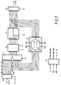
- Fig. 7 shows an embodiment of the picture transformer 13 (see Fig. 1) for performing the inverse Discrete Cosine Transform (iDCT).
- iDCT inverse Discrete Cosine Transform
- the functional structure of this inverse picture transformer corresponds to that of picture transformer 4 which has already been described. Consequently, the various elements have the same reference numerals.
- the inverse picture transformer is mainly different in that the 1- dimensional transformer 23 is now implemented for inverse transform. An embodiment of this transformer is not shown, but can be found, for example in the previously mentioned European Patent Specification EP 0 286 183.
- the control circuit 26 further supplies the various control signals, write addresses and read addresses in a different sequence.
- FIG. 8 shows, again in the form of a time diagram, various signals which occur in the picture transformer 13.
- the Figure indicates under A that the picture transformer successively receives the last column of coefficients y'(0,7) ... y'(7,7) of block N and the first column of coefficients y'(0,0) ... y'(0,7) of block N+1.
- the Figure indicates under B that these columns are available in a parallel form during periods of time T2 and T3, respectively.
- the multiplexer alternately selects a column (of the series-parallel converter 20) and a row (of the transposition memory 24).
- Fig. 8 it is assumed that there is motion in block N.
- the Figure shows under E that the shuffle network 22 first applies the even elements (EV) and subsequently the odd elements (OD) of each received column of block N to the transformer 23.
- the transform results thereof are stored in the form of columns in the first memory 241. More particularly, the last column c(7) of block N is transformed during the first half of period of time T2.
- a write address WA1 of the value C7 is applied to the first memory during this transform, which means that the result is stored in column 7 of this memory.
- a read address RA2 of the value R7 is applied to the second memory 242, as is indicated under G.
Landscapes
- Engineering & Computer Science (AREA)
- Physics & Mathematics (AREA)
- General Physics & Mathematics (AREA)
- Mathematical Physics (AREA)
- Data Mining & Analysis (AREA)
- Pure & Applied Mathematics (AREA)
- Computational Mathematics (AREA)
- Mathematical Analysis (AREA)
- Mathematical Optimization (AREA)
- Theoretical Computer Science (AREA)
- Algebra (AREA)
- Discrete Mathematics (AREA)
- Multimedia (AREA)
- Databases & Information Systems (AREA)
- Software Systems (AREA)
- General Engineering & Computer Science (AREA)
- Signal Processing (AREA)
- Compression Or Coding Systems Of Tv Signals (AREA)
- Compression, Expansion, Code Conversion, And Decoders (AREA)
Priority Applications (1)
| Application Number | Priority Date | Filing Date | Title |
|---|---|---|---|
| EP19930200999 EP0566184A3 (fr) | 1992-04-13 | 1993-04-06 | Transformateur d'image ainsi que système de télévision comportant un émetteur et un récepteur munis d'un transformateur. |
Applications Claiming Priority (3)
| Application Number | Priority Date | Filing Date | Title |
|---|---|---|---|
| EP92201042 | 1992-04-13 | ||
| EP92201042 | 1992-04-13 | ||
| EP19930200999 EP0566184A3 (fr) | 1992-04-13 | 1993-04-06 | Transformateur d'image ainsi que système de télévision comportant un émetteur et un récepteur munis d'un transformateur. |
Publications (2)
| Publication Number | Publication Date |
|---|---|
| EP0566184A2 true EP0566184A2 (fr) | 1993-10-20 |
| EP0566184A3 EP0566184A3 (fr) | 1994-11-17 |
Family
ID=26131334
Family Applications (1)
| Application Number | Title | Priority Date | Filing Date |
|---|---|---|---|
| EP19930200999 Withdrawn EP0566184A3 (fr) | 1992-04-13 | 1993-04-06 | Transformateur d'image ainsi que système de télévision comportant un émetteur et un récepteur munis d'un transformateur. |
Country Status (1)
| Country | Link |
|---|---|
| EP (1) | EP0566184A3 (fr) |
Cited By (11)
| Publication number | Priority date | Publication date | Assignee | Title |
|---|---|---|---|---|
| EP0667583A1 (fr) * | 1994-01-18 | 1995-08-16 | Daewoo Electronics Co., Ltd | Système de calcul d'un bidimensionel discrète transformé du cosinus |
| DE19520962C1 (de) * | 1995-03-18 | 1996-06-13 | United Microelectronics Corp | Zweidimensionale diskrete Echtzeit-Cosinustransformationsschaltung bzw. -Cosinusrücktransformationsschaltung |
| DE19522500C1 (de) * | 1995-03-18 | 1996-06-20 | United Microelectronics Corp | Einrichtung zur zweidimensionalen diskreten Cosinusrücktransformation |
| DE19543544A1 (de) * | 1995-04-15 | 1996-10-24 | United Microelectronics Corp | Einrichtung zur zweidimensionalen diskreten Cosinustransformation |
| FR2734926A1 (fr) * | 1995-05-31 | 1996-12-06 | United Microelectronics Corp | Circuit bi-dimensionnel en temps reel de transformation en cosinus discret/transformation inverse en cosinus discret |
| NL1000506C2 (en) * | 1995-06-07 | 1996-12-10 | United Microelectronics Corp | Real=time two=dimensional discrete cosine transform circuit |
| EP0831404A2 (fr) * | 1996-09-20 | 1998-03-25 | Nec Corporation | Circuit de calcul d'un bidimensionnel transformé discrète inverse du cosinus |
| WO2002093359A2 (fr) * | 2001-05-16 | 2002-11-21 | Qualcomm Incorporated | Appareil et procede de decodage et procede de decodage et de calcul d'une transformee en cosinus discrets inverse par un processeur butterfly |
| CN100448293C (zh) * | 2005-02-03 | 2008-12-31 | 联想(北京)有限公司 | 一种二维离散余弦变换装置及方法 |
| US7649939B2 (en) | 2001-05-16 | 2010-01-19 | Qualcomm Incorporated | Apparatus and method for decoding and computing a discrete cosine transform using a butterfly processor |
| EP1553523A3 (fr) * | 1997-04-30 | 2010-10-06 | Canon Kabushiki Kaisha | Compression avec transformée en cosinus discrète (DCT) |
Citations (5)
| Publication number | Priority date | Publication date | Assignee | Title |
|---|---|---|---|---|
| US4189748A (en) * | 1977-08-23 | 1980-02-19 | Northrop Corporation | Video bandwidth reduction system using a two-dimensional transformation, and an adaptive filter with error correction |
| EP0286183A1 (fr) * | 1987-04-10 | 1988-10-12 | Koninklijke Philips Electronics N.V. | Système de transmission de télévision utilisant le codage par transformée |
| EP0424119A2 (fr) * | 1989-10-19 | 1991-04-24 | Zoran Corporation | Appareil à circuit intégré DCT/IDCT à recyclage utilisant un multiplicateur accumulateur unique et une seule mémoire à accès aléatoire |
| US5181183A (en) * | 1990-01-17 | 1993-01-19 | Nec Corporation | Discrete cosine transform circuit suitable for integrated circuit implementation |
| FR2683694A1 (fr) * | 1991-11-08 | 1993-05-14 | Matra Communication | Dispositif de codage de signal video a activite temporelle. |
-
1993
- 1993-04-06 EP EP19930200999 patent/EP0566184A3/fr not_active Withdrawn
Patent Citations (5)
| Publication number | Priority date | Publication date | Assignee | Title |
|---|---|---|---|---|
| US4189748A (en) * | 1977-08-23 | 1980-02-19 | Northrop Corporation | Video bandwidth reduction system using a two-dimensional transformation, and an adaptive filter with error correction |
| EP0286183A1 (fr) * | 1987-04-10 | 1988-10-12 | Koninklijke Philips Electronics N.V. | Système de transmission de télévision utilisant le codage par transformée |
| EP0424119A2 (fr) * | 1989-10-19 | 1991-04-24 | Zoran Corporation | Appareil à circuit intégré DCT/IDCT à recyclage utilisant un multiplicateur accumulateur unique et une seule mémoire à accès aléatoire |
| US5181183A (en) * | 1990-01-17 | 1993-01-19 | Nec Corporation | Discrete cosine transform circuit suitable for integrated circuit implementation |
| FR2683694A1 (fr) * | 1991-11-08 | 1993-05-14 | Matra Communication | Dispositif de codage de signal video a activite temporelle. |
Non-Patent Citations (3)
| Title |
|---|
| INTEGRATION, THE VLSI JOURNAL, vol.5, no.2, June 1987, AMSTERDAM NL pages 159 - 169 B.SIKSTR\M ET AL 'A HIGH SPEED 2-D DISCRETE COSINE TRANSFORM CHIP' * |
| PROCEEDINGS OF ICASSP 87, IEEE PRESS NEW YORK US, vol.1/4, 6 April 1987, DALLAS US pages 547 - 550, XP000039814 N.DEMASSIEUX ET AL 'AN OPTIMIZED VLSI ARCHICTETURE FOR A MULTIFORMAT DISCRETE COSINE TRANSFORM' * |
| PROCEEDINGS OF ICASSP 89, IEEE PRESS NEW YORK US, vol.4, 23 May 1989, GLASGOW SCOTLAND UK pages 2413 - 2416, XP000090102 S.G.SMITH 'GENERIC ASIC ARCHITECTURE AND SYNTHESIS SCHEME FOR DSP' * |
Cited By (16)
| Publication number | Priority date | Publication date | Assignee | Title |
|---|---|---|---|---|
| EP0667583A1 (fr) * | 1994-01-18 | 1995-08-16 | Daewoo Electronics Co., Ltd | Système de calcul d'un bidimensionel discrète transformé du cosinus |
| DE19520962C1 (de) * | 1995-03-18 | 1996-06-13 | United Microelectronics Corp | Zweidimensionale diskrete Echtzeit-Cosinustransformationsschaltung bzw. -Cosinusrücktransformationsschaltung |
| DE19522500C1 (de) * | 1995-03-18 | 1996-06-20 | United Microelectronics Corp | Einrichtung zur zweidimensionalen diskreten Cosinusrücktransformation |
| GB2301203A (en) * | 1995-03-18 | 1996-11-27 | United Microelectronics Corp | Real time two-dimensional discrete cosine transform/inverse discrete cosine transform circuit |
| GB2301203B (en) * | 1995-03-18 | 2000-01-12 | United Microelectronics Corp | Real time two dimensional discrete cosine transform/inverse discrete cosine transform circuit |
| DE19543544A1 (de) * | 1995-04-15 | 1996-10-24 | United Microelectronics Corp | Einrichtung zur zweidimensionalen diskreten Cosinustransformation |
| FR2734926A1 (fr) * | 1995-05-31 | 1996-12-06 | United Microelectronics Corp | Circuit bi-dimensionnel en temps reel de transformation en cosinus discret/transformation inverse en cosinus discret |
| NL1000506C2 (en) * | 1995-06-07 | 1996-12-10 | United Microelectronics Corp | Real=time two=dimensional discrete cosine transform circuit |
| EP0831404A3 (fr) * | 1996-09-20 | 1999-10-20 | Nec Corporation | Circuit de calcul d'un bidimensionnel transformé discrète inverse du cosinus |
| EP0831404A2 (fr) * | 1996-09-20 | 1998-03-25 | Nec Corporation | Circuit de calcul d'un bidimensionnel transformé discrète inverse du cosinus |
| EP1553523A3 (fr) * | 1997-04-30 | 2010-10-06 | Canon Kabushiki Kaisha | Compression avec transformée en cosinus discrète (DCT) |
| WO2002093359A2 (fr) * | 2001-05-16 | 2002-11-21 | Qualcomm Incorporated | Appareil et procede de decodage et procede de decodage et de calcul d'une transformee en cosinus discrets inverse par un processeur butterfly |
| WO2002093359A3 (fr) * | 2001-05-16 | 2004-01-29 | Qualcomm Inc | Appareil et procede de decodage et procede de decodage et de calcul d'une transformee en cosinus discrets inverse par un processeur butterfly |
| US6876704B2 (en) | 2001-05-16 | 2005-04-05 | Qualcomm, Incorporated | Apparatus and method for encoding and computing a discrete cosine transform using a butterfly processor |
| US7649939B2 (en) | 2001-05-16 | 2010-01-19 | Qualcomm Incorporated | Apparatus and method for decoding and computing a discrete cosine transform using a butterfly processor |
| CN100448293C (zh) * | 2005-02-03 | 2008-12-31 | 联想(北京)有限公司 | 一种二维离散余弦变换装置及方法 |
Also Published As
| Publication number | Publication date |
|---|---|
| EP0566184A3 (fr) | 1994-11-17 |
Similar Documents
| Publication | Publication Date | Title |
|---|---|---|
| JP2630802B2 (ja) | 変換符号化を用いたテレビジョン転送システム | |
| KR100246878B1 (ko) | 역이산 코사인변환 프로세서, 이산 코사인 변환계수의 매트릭스를 역변환하기 위한 방법 및 그 장치 | |
| EP0621730B1 (fr) | Schéma à double tampon pour générer plusieur strains de données à partir de données enregistrées | |
| US4788589A (en) | Method and apparatus for transmitting video data | |
| US4189748A (en) | Video bandwidth reduction system using a two-dimensional transformation, and an adaptive filter with error correction | |
| US5099325A (en) | Process and circuit for block matching in two-dimensional picture signals | |
| EP0640908A1 (fr) | Réduction de bruit dans des signaux d'image | |
| EP0565223A2 (fr) | Procédé de compression d'un signal d'image numérique avec ordonnement et formattage des données codées et restitution d'images partielles à partir des données | |
| US7646813B2 (en) | Encoding circuit for transform coding of a picture signal and decoding circuit for decoding said signal | |
| US5550765A (en) | Method and apparatus for transforming a multi-dimensional matrix of coefficents representative of a signal | |
| EP0566184A2 (fr) | Transformateur d'image ainsi que système de télévision comportant un émetteur et un récepteur munis d'un transformateur | |
| US4881192A (en) | One-dimensional linear picture transformer | |
| US5777679A (en) | Video decoder including polyphase fir horizontal filter | |
| JP3285220B2 (ja) | デジタル形式で画像信号を伝送するテレビジョンシステム | |
| US6507673B1 (en) | Method and apparatus for video encoding decision | |
| US4953020A (en) | Television transmission system with differential encoding of transform coefficients | |
| JPH08329047A (ja) | 離散コサイン変換回路,離散コサイン逆変換回路,mpegビデオエンコーダ,mpegビデオデコーダ | |
| US6501508B1 (en) | Video format converter for digital receiving system | |
| US4953018A (en) | Television Transmission system using transmission of basic picture weighting factors | |
| JPH0646405A (ja) | 画像変換器およびそれを具える送信機と受信機を持つテレビジョンシステム | |
| US5905660A (en) | Discrete cosine transform circuit for processing an 8×8 block and two 4×8 blocks | |
| US5528736A (en) | Apparatus and method for performing a two-dimensional block data transform without transposition | |
| JPH0844709A (ja) | 2次元逆離散形コサイン変換(idct)装置 | |
| JP3347603B2 (ja) | 符号化装置及び復号化装置 | |
| CN1126410A (zh) | 数字视频信号的并行解码装置 |
Legal Events
| Date | Code | Title | Description |
|---|---|---|---|
| PUAI | Public reference made under article 153(3) epc to a published international application that has entered the european phase |
Free format text: ORIGINAL CODE: 0009012 |
|
| AK | Designated contracting states |
Kind code of ref document: A2 Designated state(s): DE FR GB IT |
|
| RAP1 | Party data changed (applicant data changed or rights of an application transferred) |
Owner name: N.V. PHILIPS' GLOEILAMPENFABRIEKEN |
|
| PUAL | Search report despatched |
Free format text: ORIGINAL CODE: 0009013 |
|
| AK | Designated contracting states |
Kind code of ref document: A3 Designated state(s): DE FR GB IT |
|
| 17P | Request for examination filed |
Effective date: 19950517 |
|
| D17P | Request for examination filed (deleted) | ||
| STAA | Information on the status of an ep patent application or granted ep patent |
Free format text: STATUS: THE APPLICATION IS DEEMED TO BE WITHDRAWN |
|
| 18D | Application deemed to be withdrawn |
Effective date: 19950518 |