EP0565968A2 - Mounting device for attaching cable harnesses - Google Patents
Mounting device for attaching cable harnesses Download PDFInfo
- Publication number
- EP0565968A2 EP0565968A2 EP93105472A EP93105472A EP0565968A2 EP 0565968 A2 EP0565968 A2 EP 0565968A2 EP 93105472 A EP93105472 A EP 93105472A EP 93105472 A EP93105472 A EP 93105472A EP 0565968 A2 EP0565968 A2 EP 0565968A2
- Authority
- EP
- European Patent Office
- Prior art keywords
- opening
- guide channel
- housing
- strap
- tape
- Prior art date
- Legal status (The legal status is an assumption and is not a legal conclusion. Google has not performed a legal analysis and makes no representation as to the accuracy of the status listed.)
- Granted
Links
- 239000000853 adhesive Substances 0.000 claims abstract description 4
- 230000001070 adhesive effect Effects 0.000 claims abstract description 4
- 210000002105 tongue Anatomy 0.000 claims description 4
- 230000002093 peripheral effect Effects 0.000 claims description 3
- 238000000034 method Methods 0.000 description 4
- 210000003811 finger Anatomy 0.000 description 2
- 230000000881 depressing effect Effects 0.000 description 1
- 238000001746 injection moulding Methods 0.000 description 1
- 210000003813 thumb Anatomy 0.000 description 1
Images

Classifications
-
- H—ELECTRICITY
- H05—ELECTRIC TECHNIQUES NOT OTHERWISE PROVIDED FOR
- H05K—PRINTED CIRCUITS; CASINGS OR CONSTRUCTIONAL DETAILS OF ELECTRIC APPARATUS; MANUFACTURE OF ASSEMBLAGES OF ELECTRICAL COMPONENTS
- H05K13/00—Apparatus or processes specially adapted for manufacturing or adjusting assemblages of electric components
- H05K13/06—Wiring by machine
-
- H—ELECTRICITY
- H02—GENERATION; CONVERSION OR DISTRIBUTION OF ELECTRIC POWER
- H02G—INSTALLATION OF ELECTRIC CABLES OR LINES, OR OF COMBINED OPTICAL AND ELECTRIC CABLES OR LINES
- H02G1/00—Methods or apparatus specially adapted for installing, maintaining, repairing or dismantling electric cables or lines
- H02G1/02—Methods or apparatus specially adapted for installing, maintaining, repairing or dismantling electric cables or lines for overhead lines or cables
- H02G1/04—Methods or apparatus specially adapted for installing, maintaining, repairing or dismantling electric cables or lines for overhead lines or cables for mounting or stretching
-
- H—ELECTRICITY
- H02—GENERATION; CONVERSION OR DISTRIBUTION OF ELECTRIC POWER
- H02G—INSTALLATION OF ELECTRIC CABLES OR LINES, OR OF COMBINED OPTICAL AND ELECTRIC CABLES OR LINES
- H02G7/00—Overhead installations of electric lines or cables
- H02G7/05—Suspension arrangements or devices for electric cables or lines
- H02G7/06—Suspensions for lines or cables along a separate supporting wire, e.g. S-hook
- H02G7/10—Flexible members or lashings wrapped around both the supporting wire and the line or cable
Definitions
- the invention relates to a mounting device for tying cable bundles by means of a plastic strapping provided with transverse ribs or tines of indefinite length and a locking lock also made of hard-elastic plastic, the lock known from DE 35 25 351 A1 with an opening for carrying the tensioning strap and with two interlocking tongues interacting with the transverse ribs or prongs is provided.
- the invention is based on a mounting device known from EP 0 303 723 A1.
- This essentially consists of a housing with a receiving part for the wound tensioning strap, an opening for exiting and re-entering the tensioning strap, a guide channel for feeding the tensioning strap to the opening, another channel arranged above the guide channel for feeding the locking locks in front of the outlet opening the tensioning strap, and a knife arranged behind the lock for severing the strap ends protruding from the locking lock.
- the object of the invention is therefore to design the aforementioned assembly device in such a way that the locking locks, which can be torn off by adhesive bars, are inserted into the assembly device and conveyed into the locking position in the manner in which they are ejected from the injection molding machines, and also that the tape is transported through the housing is trained to be more user-friendly.
- the assembly device shown in the figures is used for tying cable bundles by means of an endless plastic tension band in conjunction with locking locks, which are also made of hard elastic plastic.
- the tensioning straps described, for example, in DE 35 25 351 A1 are provided with transverse ribs or serrations and are first passed through the opening in the locking lock from one side and, after the cable bundle has been reclamped, inserted back into the same opening from the other side. In the opening are two mutually opposite, spring-loaded latching tongues that cooperate with the transverse ribs of the tension band.
- the assembly device consists of a handy housing 1 with a receiving part 2 for the wound tension band 3.
- a guide channel 4 for the tension band 3 is provided in the interior of the housing, which can be pivoted at 5 in the housing 1 before its entry end 13 stored and with its outlet opening 14 is directed to a housing opening 6.
- the guide channel 4 is held in the upper position by means of a spring 7.
- a further channel 8 is arranged above this guide channel 4, which channel is designed to receive the locking locks 9.
- the channel 8 can be closed from above with a cover channel 10, which is pivotally connected to the housing 1 at 11 and can be closed at the front end by a latching mechanism (not shown).
- a pivotally mounted pawl 12 which is pressed by spring force against the upper edge of the hole of the lock 9 located just in front of the guide channel 4.
- the channel 8 is guided around to the exit end of the guide channel 4 in such a way that the locks 9, which are connected to one another by tear-off webs, can be inserted with their opening directly into the holding position in front of the tape exit opening 14 of the guide channel 4.
- the tightening strap 3 is driven by means of a roller 15 which can be rotated by hand, which is knurled on its peripheral surface 16 and can be pressed with it against the serrated tightening strap 3.
- the roller 15 is located below the guide channel 4 just before the tape exit opening 14 and protrudes with a part of its peripheral surface 16 from the housing 1, so that the roller 15 can be easily rotated with the index finger of the hand that holds the mounting device.
- a lever 17 is pivotally mounted in the housing 1 above the pivotable guide channel 4. This lever 17 carries in its front third a rotatably mounted roller 18 which rests on the front area of the guide channel 4. The lever 17 is extended somewhat beyond the roller bearing and has at its end 19 a laterally projecting pin 20 which understands laterally in an arcuate elongated hole 21 from the housing and can be pressed down manually against the force of the spring 7.
- a knife 22 is arranged in the housing 1 below the band exit 14 and its cutting edge 23 is directed towards the tensioning band.
- the tensioning band 3 is pressed onto the cutting edge 23 and cut off exactly between the band exit 14 and the locking lock 9, which is also pulled down by the band 3.
- the assembly device which is loaded with a tensioning roller 3 and chain-like interlocking locks 9, has its opening 6 in front of a cable bundle 24.
Landscapes
- Engineering & Computer Science (AREA)
- Manufacturing & Machinery (AREA)
- Microelectronics & Electronic Packaging (AREA)
- Basic Packing Technique (AREA)
- Package Frames And Binding Bands (AREA)
- Insertion, Bundling And Securing Of Wires For Electric Apparatuses (AREA)
- Clamps And Clips (AREA)
Abstract
Das zum Festbinden von Kabelbündeln mittels eines Kunststoffspannbandes (3) vorgesehene Montagegerät besteht aus einem Gehäuse (1) mit einem Aufnahmeteil (2) für ein aufgewickeltes Spannband (3), einer Öffnung (14) zum Aus- und Wiedereintritt des Spannbandes (3), einem Führungskanal (4) für die Zuführung des Spannbandes (3) zur Öffnung (14), einem weiteren Kanal (8) für die Zuführung von durch Haftstege abreißbar miteinander verbundenen Verriegelungsschlössern (9) vor die Austrittsöffnung (14) des Spannbandes (3), sowie einem Messer (22) zum Abtrennen der Bandenden. Um die Verriegelungsschlösser (9) leichter vor die Austrittsöffnung (14) führen zu können und den Bandtransport durch das Gehäuse (1) bedienungsfreundlicher zu gestalten, ist der Führungskanal (8) für die Verriegelungsschlösser (9) zur Bandaustrittsöffnung (14) derart herumgeführt, daß die Schlösser (9) mit ihrer Öffnung in eine Halteposition vor der Bandaustrittsöffnung (14) hineinziehbar sind, und ist der Führungskanal (4) im Gehäuse (1) derart schwenkbar gelagert, daß die Bandaustrittsöffnung (14) in den Schnittbereich des Messers (22) drückbar ist.The assembly device provided for tying cable bundles by means of a plastic tensioning strap (3) consists of a housing (1) with a receiving part (2) for a wound tensioning strap (3), an opening (14) for exiting and re-entering the tensioning strap (3), a guide channel (4) for the supply of the tension band (3) to the opening (14), a further channel (8) for the supply of locking locks (9) which can be torn off by adhesive bars in front of the outlet opening (14) of the tension band (3), and a knife (22) for severing the tape ends. In order to be able to guide the locking locks (9) more easily in front of the outlet opening (14) and to make the strap transport through the housing (1) more user-friendly, the guide channel (8) for the locking locks (9) is led around to the strap outlet opening (14) in such a way that the locks (9) can be pulled with their opening into a holding position in front of the tape outlet opening (14), and the guide channel (4) is pivotally mounted in the housing (1) in such a way that the tape outlet opening (14) into the cutting area of the knife (22) is pushable.
Description
Die Erfindung bezieht sich auf ein Montagegerät zum Festbinden von Kabelbündeln mittels eines mit Querrippen oder Zacken versehenen Kunststoffspannbandes von unbestimmter Länge sowie eines ebenfalls aus hartelastischem Kunststoff hergestellten Verriegelungsschlosses, wobei das durch DE 35 25 351 A1 bekannte Schloß mit einer Öffnung zum Durchführen des Spannbandes und mit zwei mit den Querrippen oder Zacken zusammenwirkenden, einander gegenüberliegenden Rastzungen versehen ist.The invention relates to a mounting device for tying cable bundles by means of a plastic strapping provided with transverse ribs or tines of indefinite length and a locking lock also made of hard-elastic plastic, the lock known from DE 35 25 351 A1 with an opening for carrying the tensioning strap and with two interlocking tongues interacting with the transverse ribs or prongs is provided.
Die Erfindung geht hierbei aus von einem durch die EP 0 303 723 A1 bekannten Montagegerät. Dieses besteht im wesentlichen aus einem Gehäuse mit Aufnahmeteil für das gewickelte Spannband, einer Öffnung zum Aus- und Wiedereintritt des Spannbandes, einem Führungskanal für die Zuführung des Spannbandes zur Öffnung, einem weiteren, oberhalb des Führungskanals angeordneten Kanal für die Zuführung der Verriegelungsschlösser vor die Austrittsöffnung des Spannbandes, sowie einem hinter dem Schloß angeordneten Messer zum Abtrennen der aus dem Verriegelungsschloß vorstehenden Bandenden.The invention is based on a mounting device known from EP 0 303 723 A1. This essentially consists of a housing with a receiving part for the wound tensioning strap, an opening for exiting and re-entering the tensioning strap, a guide channel for feeding the tensioning strap to the opening, another channel arranged above the guide channel for feeding the locking locks in front of the outlet opening the tensioning strap, and a knife arranged behind the lock for severing the strap ends protruding from the locking lock.
Bei diesem bekannten Montagegerät wird es als Nachteil empfunden, daß die Verriegelungsschlösser auf einer besonderen Stange magaziniert, d.h. aufeinandergestapelt und dann in den oberen Führungskanal eingeschoben werden müssen, um dann mittels Federkraft vorgetrieben und in ein am Gehäuse schwenkbar gelagertes Kopfteil übergeben zu werden, welches jeweils das vordere Schloß vor dem Bandaustritt positioniert.In this known assembly device, it is perceived as a disadvantage that the locking locks have to be magazined on a special rod, that is, stacked on top of one another and then inserted into the upper guide channel, in order to then be driven by spring force and transferred to a head part pivotably mounted on the housing, each of which the front lock is positioned in front of the belt exit.
Ferner ist es unbefriedigend, daß das Spannband direkt von Hand durch den Führungskanal gedrückt und nach dem Umschlingen des Bündels und Einfädeln der Bandspitze im Schloß wieder von Hand zurückgezogen werden muß, bevor das gespannte Band mit dem Messer abgeschnitten werden kann.Furthermore, it is unsatisfactory that the tensioning band must be pressed directly by hand through the guide channel and, after the bundle has been looped around and the banding tip threaded into the lock, must be pulled back by hand again before the tensioned band can be cut off with the knife.
Aufgabe der Erfindung ist es daher, das vorgenannte Montagegerät so zu gestalten, daß die durch Haftstege abreißbar miteinander verbundenen Verriegelungsschlösser so, wie sie aus den Spritzgießmaschinen ausgeworfen werden, in das Montagegerät eingelegt und in die Verriegelungsposition befördert werden und daß ferner der Bandtransport durch das Gehäuse bedienungsfreundlicher ausgebildet wird.The object of the invention is therefore to design the aforementioned assembly device in such a way that the locking locks, which can be torn off by adhesive bars, are inserted into the assembly device and conveyed into the locking position in the manner in which they are ejected from the injection molding machines, and also that the tape is transported through the housing is trained to be more user-friendly.
Zur Lösung dieser Aufgabe wird gemäß den im Anspruch 1 angegebenen Merkmalen vorgeschlagen, den Führungskanal für die Verriegelungsschlösser zur Bandaustrittsöffnung derart herumzuführen, daß die Schlösser in eine Halteposition vor dem Bandaustritt einführbar sind und den Führungskanal für das Spannband im Gehäuse schwenkbar zu lagern, so daß die Bandaustrittsöffnung in den Schnittbereich des Messers drückbar ist.To achieve this object, it is proposed according to the features specified in claim 1 to guide the guide channel for the locking locks to the tape exit opening in such a way that the locks can be inserted into a holding position in front of the tape exit and to pivotally mount the guide channel for the tensioning strap in the housing, so that the Band outlet opening can be pressed into the cutting area of the knife.
Weitere Merkmale der Erfindung gehen aus den Unteransprüchen hervor, wobei im einzelnen folgende Vorteile damit verbunden sind:
Durch Anwendung des Anspruchs 2 wird die Handhabung wesentlich erleichtert, indem das gerändelte Rad mit dem Zeigefinger der gleichen Hand betätigt werden kann, die auch das Montagegerät hält. So bleibt die andere Hand frei für das Umschlingen des Bündels mit dem Band und zum Einfädeln des Bandendes in das Verriegelungsschloß.Further features of the invention emerge from the subclaims, the following individual advantages being associated therewith:
By applying
Durch die schwenkbar gelagerte Klinke gemäß Anspruch 3 wird die positionsgenaue Lage des Schlosses vor der Bandaustrittsöffnung während des Durchführens des Bandes und des Einrastens des Bandendes nach dem Umschlingen des Bündels sichergestellt und durch die Maßnahmen nach Anspruch 4 wird das Niederdrücken des Führungskanals am Ende der Umschlingungsoperation erleichtert, wobei der seitlich abstehende Stift praktisch vom Daumen der das Gerät haltenden Hand betätigt werden kann.Due to the pivotally mounted pawl according to
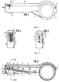
In der Zeichnung ist ein Ausführungsbeispiel der Erfindung dargestellt und soll nachfolgend näher erläutert werden. Es zeigt
- Fig. 1
- ein Montagegerät in Vorderansicht,
- Fig. 2
- das Gerät in Seitenansicht mit Blick auf den Bandaustritt,
- Fig. 3
- ein Längsschnitt durch das Gerät gemäß Linie III - III in
Figur 2, - Fig. 4
- ein Querschnitt durch das Gerät gemäß Linie IV - IV in
Figur 3, - Fig. 5
- ein Längsschnitt wie
Figur 3 mit eingelegtem Spannband und Verriegelungsschlössern vor dem Umspannen eines Kabelbündels, - Fig. 6
- das Montagegerät nach
Figur 5 nach dem Umspannen des Kabelbündels und - Fig. 7
- das Montagegerät beim Abdrücken des Spannbandes.
- Fig. 1
- a mounting device in front view,
- Fig. 2
- the device in side view with a view of the tape exit,
- Fig. 3
- 2 shows a longitudinal section through the device according to line III-III in FIG. 2,
- Fig. 4
- 3 shows a cross section through the device according to line IV-IV in FIG. 3,
- Fig. 5
- 3 shows a longitudinal section as in FIG. 3 with an inserted tensioning strap and locking locks before reclamping a cable bundle,
- Fig. 6
- the assembly device of Figure 5 after reclamping the cable bundle and
- Fig. 7
- the assembly device when pulling off the strap.
Das in den Figuren dargestellte Montagegerät dient zum Festbinden von Kabelbündeln mittels eines endlosen Kunststoffspannbandes in Verbindung mit Verriegelungsschlössern, die ebenfalls aus hartelastischem Kunststoff hergestellt sind. Die beispielsweise in DE 35 25 351 A1 beschriebenen Spannbänder sind mit Querrippen oder Zacken versehen und werden durch die Öffnung im Verriegelungsschloß zunächst von der einen Seite hindurchgeführt und nach dem Umspannen des Kabelbündels von der anderen Seite in die gleiche öffnung zurückgesteckt. In der Öffnung befinden sich zwei einander gegenüberliegende, auffederbare Rastzungen, die mit den Querrippen des Spannbandes zusammenwirken.The assembly device shown in the figures is used for tying cable bundles by means of an endless plastic tension band in conjunction with locking locks, which are also made of hard elastic plastic. The tensioning straps described, for example, in DE 35 25 351 A1 are provided with transverse ribs or serrations and are first passed through the opening in the locking lock from one side and, after the cable bundle has been reclamped, inserted back into the same opening from the other side. In the opening are two mutually opposite, spring-loaded latching tongues that cooperate with the transverse ribs of the tension band.
Das Montagegerät besteht aus einem handlichen Gehäuse 1 mit einem Aufnahmeteil 2 für das aufgewickelte Spannband 3. Wie aus dem Längsschnitt gemäß Figur 3 ersichtlich, ist im Gehäuseinnern ein Führungskanal 4 für das Spannband 3 vorgesehen, welcher vor seinem Eintrittsende 13 bei 5 schwenkbar im Gehäuse 1 gelagert und mit seiner Austrittsöffnung 14 auf eine Gehäuseöffnung 6 gerichtet ist. Der Führungskanal 4 wird mittels einer Feder 7 in der oberen Position gehalten.The assembly device consists of a handy housing 1 with a receiving
Oberhalb dieses Führungskanals 4 ist ein weiterer Kanal 8 angeordnet, weicher zur Aufnahme der Verriegelungsschlösser 9 ausgebildet ist. Der Kanal 8 ist von oben mit einer Abdeckrinne 10 verschließbar, welche bei 11 schwenkbar mit dem Gehäuse 1 verbunden und am vorderen Ende durch einen nicht näher dargestellten Einrastmechanismus verschließbar ist.A further channel 8 is arranged above this
Ebenfalls am vorderen Ende der Abdeckrinne 10 befindet sich eine schwenkbar gelagerte Klinke 12, welche mit Federkraft gegen den jeweils oberen Lochrand des gerade vor dem Führungskanal 4 befindlichen Schlosses 9 angedrückt wird.Also at the front end of the
Der Kanal 8 ist zum Austrittsende des Führungskanals 4 derart herumgeführt, daß die Schlösser 9, welche durch Haftstege abreißbar miteinander verbunden sind, mit ihrer öffnung direkt in die Halteposition vor der Bandaustrittsöffnung 14 des Führungskanals 4 einsetzbar sind.The channel 8 is guided around to the exit end of the
Das Spannband 3 wird mittels einer von Hand drehbaren Rolle 15 vorgetrieben, welche an ihrer Umfangsfläche 16, gerändelt ist und mit dieser gegen das gezackte Spannband 3 andrückbar ist. Die Rolle 15 befindet sich unterhalb des Führungskanals 4 kurz vor der Bandaustrittsöffnung 14 und steht mit einem Teil seiner Umfangsfläche 16 aus dem Gehäuse 1 vor, so daß die Rolle 15 leicht mit dem Zeigefinger der Hand, die das Montagegerät hält, gedreht werden kann.The tightening
Oberhalb des schwenkbaren Führungskanals 4 ist ein Hebel 17 im Gehäuse 1 schwenkbar gelagert. Dieser Hebel 17 trägt in seinem vorderen Drittel eine drehbar gelagerte Rolle 18, welche auf dem vorderen Bereich des Führungskanals 4 aufliegt. Der Hebel 17 ist noch etwas über die Rollenlagerung verlängert und besitzt an seinem Ende 19 einen seitlich abstehenden Stift 20, welcher in einem bogenförmigen Langloch 21 aus dem Gehäuse seitlich versteht und von Hand gegen die Kraft der Feder 7 niederdrückbar ist.A
Unterhalb des Bandaustritts 14 ist im Gehäuse 1 ein Messer 22 angeordnet, das mit seiner Schneide 23 auf das Spannband gerichtet ist. Beim Abwärtsdrücken des schwenkbaren Führungskanals 4 wird das Spannband 3 auf die Schneide 23 gedrückt und genau zwischen Bandaustritt 14 und Verriegelungsschloß 9 abgeschnitten, welches vom Band 3 mit heruntergezogen wird.A
Die Arbeitsweise mit dem Montagegerät ist in den Figuren 5 bis 7 anschaulich dargestellt.The method of operation with the assembly device is clearly illustrated in FIGS. 5 to 7.
Bei der ersten Arbeitsposition befindet sich das Montagegerät, welches mit einer Spannbandrolle 3 und kettenförmig zusammenhängenden Schlössern 9 beladen ist, mit seiner öffnung 6 vor einem Kabelbündel 24.In the first working position, the assembly device, which is loaded with a
Durch Drehen der gerändelten Rolle 15 in Pfeilrichtung "V" wird das Spannband 3 vorgetrieben. Dann wird mit der freien Hand das Ende des Spannbandes 3 um das Bündel 24 in Richtung des Pfeiles "P" herumgeführt und von der anderen Seite in die öffnung des Verriegelungsschlosses 9 wieder eingefädelt und so weit eingedrückt, bis mindestens eine Querrippe von der Ractzunge erfaßt ist.
Sodann wird das Band 3 durch Drehen der Rolle in Pfeilrichtung "Z", wie aus Figur 6 ersichtlich, wieder zurückgezogen und um das Bündel 24 gespannt.
Nun ist der Bindevorgang beendet und der Führungskanal 4 wird über den Hebel 17 und die Andrückrolle 18 nach unten gedrückt, wobei das aus dem Schloß 9 vorstehende Bandende auf die Scheide 23 des Messers 22 trifft und dabei abgeschnitten wird (Figur 7). Durch das Niederdrücken des Schlosses 9 ist das über Haftstege verbundene, nachfolgende Schloß 9 gleichzeitig in seine Arbeitsposition gezogen worden und wird von der Klinke 12 in dieser Position für den nächsten Bindevorgang fixiert.By turning the
The
Now the binding process is finished and the
Claims (4)
Applications Claiming Priority (2)
| Application Number | Priority Date | Filing Date | Title |
|---|---|---|---|
| DE4212789 | 1992-04-16 | ||
| DE4212789A DE4212789C1 (en) | 1992-04-16 | 1992-04-16 |
Publications (3)
| Publication Number | Publication Date |
|---|---|
| EP0565968A2 true EP0565968A2 (en) | 1993-10-20 |
| EP0565968A3 EP0565968A3 (en) | 1995-03-29 |
| EP0565968B1 EP0565968B1 (en) | 1996-09-25 |
Family
ID=6456981
Family Applications (1)
| Application Number | Title | Priority Date | Filing Date |
|---|---|---|---|
| EP93105472A Expired - Lifetime EP0565968B1 (en) | 1992-04-16 | 1993-04-02 | Mounting device for attaching cable harnesses |
Country Status (5)
| Country | Link |
|---|---|
| US (2) | US5351611A (en) |
| EP (1) | EP0565968B1 (en) |
| JP (1) | JP2566721B2 (en) |
| DE (1) | DE4212789C1 (en) |
| ES (1) | ES2094402T3 (en) |
Cited By (3)
| Publication number | Priority date | Publication date | Assignee | Title |
|---|---|---|---|---|
| DE19828007C1 (en) * | 1998-06-24 | 1999-12-16 | Raymond A & Cie | Arrangement of fasteners for holding bundles covered with cable ties |
| EP1231144A1 (en) * | 2001-02-12 | 2002-08-14 | Hellermann Tyton GmbH | Device for bundling articles with a strap loop |
| WO2013140119A3 (en) * | 2012-03-21 | 2013-11-14 | Natural Biotechnology Sprl | Pre-harvest treatment |
Families Citing this family (7)
| Publication number | Priority date | Publication date | Assignee | Title |
|---|---|---|---|---|
| DE3702840A1 (en) * | 1986-02-06 | 1987-08-20 | Ryobi Ltd | ARRANGEMENT OF CONNECTED METAL PARTS AND METHOD FOR THE PRODUCTION THEREOF |
| DE19523870A1 (en) * | 1995-06-30 | 1997-01-02 | Mann & Hummel Filter | Suction device made of thermoplastic |
| US5944944A (en) * | 1997-10-07 | 1999-08-31 | Gwo-Jiang; Liaw | Structural improvement of banding gun |
| DE19859672C2 (en) * | 1998-12-23 | 2001-04-12 | Raymond A & Cie | Process for the automated bundling of cable harnesses and automatic device for carrying out the process |
| JP3748504B2 (en) * | 2000-02-24 | 2006-02-22 | 仁礼工業株式会社 | Bundling device |
| EP1231158A1 (en) * | 2001-02-12 | 2002-08-14 | Hellermann Tyton GmbH | Strip of interconnected locking pieces for tightening straps and tool for their application |
| CN113451918B (en) * | 2021-08-03 | 2022-12-27 | 江西德伊智能电力有限公司 | Distribution box |
Citations (3)
| Publication number | Priority date | Publication date | Assignee | Title |
|---|---|---|---|---|
| FR2223141A1 (en) * | 1973-03-26 | 1974-10-25 | Nifco Inc | |
| US4763700A (en) * | 1987-08-18 | 1988-08-16 | Nirei Industry Co., Ltd. | Binding tool |
| EP0297337B1 (en) * | 1987-07-01 | 1992-08-12 | RTGAMMA S.p.A | Method and apparatus for automatically binding cables, by a continuous strip |
Family Cites Families (7)
| Publication number | Priority date | Publication date | Assignee | Title |
|---|---|---|---|---|
| US3570554A (en) * | 1967-09-12 | 1971-03-16 | Hellermann Gmbh P | Method of tieing a bundle of cables |
| CH510944A (en) * | 1967-11-14 | 1971-07-31 | Hellermann Gmbh P | Tool for tying wire harnesses |
| US3489076A (en) * | 1968-05-20 | 1970-01-13 | Ty Lok Assembly Systems Inc | Automatic strapping apparatus |
| US3633633A (en) * | 1970-01-27 | 1972-01-11 | Ty Lok Assembly Systems Inc | Strapping apparatus |
| JPS6121316A (en) * | 1984-07-10 | 1986-01-30 | 株式会社 ニフコ | Bundling tool |
| DE3525351C2 (en) * | 1985-07-16 | 1994-09-15 | Raymond A Gmbh & Co Kg | cable ties |
| DE303723T1 (en) * | 1987-08-18 | 1992-11-26 | Nirei Industry Co. Ltd., Mitaka, Tokio/Tokyo | TOOL TO BIND. |
-
1992
- 1992-04-16 DE DE4212789A patent/DE4212789C1/de not_active Expired - Fee Related
-
1993
- 1993-04-02 EP EP93105472A patent/EP0565968B1/en not_active Expired - Lifetime
- 1993-04-02 ES ES93105472T patent/ES2094402T3/en not_active Expired - Lifetime
- 1993-04-13 JP JP5085895A patent/JP2566721B2/en not_active Expired - Lifetime
- 1993-04-15 US US08/046,307 patent/US5351611A/en not_active Expired - Fee Related
-
1994
- 1994-08-16 US US08/291,691 patent/US5471920A/en not_active Expired - Fee Related
Patent Citations (3)
| Publication number | Priority date | Publication date | Assignee | Title |
|---|---|---|---|---|
| FR2223141A1 (en) * | 1973-03-26 | 1974-10-25 | Nifco Inc | |
| EP0297337B1 (en) * | 1987-07-01 | 1992-08-12 | RTGAMMA S.p.A | Method and apparatus for automatically binding cables, by a continuous strip |
| US4763700A (en) * | 1987-08-18 | 1988-08-16 | Nirei Industry Co., Ltd. | Binding tool |
Cited By (4)
| Publication number | Priority date | Publication date | Assignee | Title |
|---|---|---|---|---|
| DE19828007C1 (en) * | 1998-06-24 | 1999-12-16 | Raymond A & Cie | Arrangement of fasteners for holding bundles covered with cable ties |
| EP1231144A1 (en) * | 2001-02-12 | 2002-08-14 | Hellermann Tyton GmbH | Device for bundling articles with a strap loop |
| US6640839B2 (en) | 2001-02-12 | 2003-11-04 | Hellermann Tyton Gmbh | Arrangement for binding objects by means of a band loop |
| WO2013140119A3 (en) * | 2012-03-21 | 2013-11-14 | Natural Biotechnology Sprl | Pre-harvest treatment |
Also Published As
| Publication number | Publication date |
|---|---|
| JPH0645771A (en) | 1994-02-18 |
| ES2094402T3 (en) | 1997-01-16 |
| DE4212789C1 (en) | 1993-09-09 |
| EP0565968B1 (en) | 1996-09-25 |
| US5351611A (en) | 1994-10-04 |
| JP2566721B2 (en) | 1996-12-25 |
| EP0565968A3 (en) | 1995-03-29 |
| US5471920A (en) | 1995-12-05 |
Similar Documents
| Publication | Publication Date | Title |
|---|---|---|
| DE69313329T2 (en) | Portable tool for creating strips of cable tie elements | |
| DE3413099A1 (en) | AUTOMATIC WORKING TOOL FOR PRODUCING CONTAINERS | |
| DE1761691B2 (en) | HAND LABELING DEVICE | |
| DE3781565T2 (en) | DEVICE FOR CLOSING THE TOP OF SKI BOOTS. | |
| DE1515401B2 (en) | Hand press for pressing connection terminals onto electrical conductors | |
| EP0565968B1 (en) | Mounting device for attaching cable harnesses | |
| EP0835809B1 (en) | Tool for tying an article,particularly a bundle of cables | |
| DE2261528A1 (en) | CABLE TIES | |
| DE7211622U (en) | Cable collet | |
| EP0596363B1 (en) | Arrangement for tieing an object | |
| DE60129759T2 (en) | Binding device for tightening a binding tape | |
| EP0371044B1 (en) | Tool for tying up bundles of cables or similar with an endless ribbon | |
| DE2807056A1 (en) | DEVICE FOR PRINTING OR APPLYING ADHESIVE LABELS | |
| DE3644657C2 (en) | ||
| EP0596368B1 (en) | Arrangement for tying an object, in particular a bundle of cables | |
| EP0413160A1 (en) | Device for tensioning a strap around a package | |
| EP0596370B1 (en) | Arrangement for applying ties | |
| EP0659391B1 (en) | Tape portioning dispenser | |
| EP1231144B1 (en) | Device for bundling articles with a strap loop | |
| EP0864496B1 (en) | Tool for strapping articles, in particular bundles of cables | |
| DE2748712A1 (en) | PRESSING TOOL | |
| DE2626687A1 (en) | Hand unwinding device for self-adhesive tape roll - has core with cover plates guide slot and tape cutting device rotatably locating roll | |
| DE4339151C2 (en) | Tape unwinding device | |
| DE69829550T2 (en) | ULTRASOUND BINDING TOOL | |
| DE3135580A1 (en) | TWISTABLE KEYCHAIN |
Legal Events
| Date | Code | Title | Description |
|---|---|---|---|
| PUAI | Public reference made under article 153(3) epc to a published international application that has entered the european phase |
Free format text: ORIGINAL CODE: 0009012 |
|
| AK | Designated contracting states |
Kind code of ref document: A2 Designated state(s): BE ES FR GB IT NL SE |
|
| PUAL | Search report despatched |
Free format text: ORIGINAL CODE: 0009013 |
|
| AK | Designated contracting states |
Kind code of ref document: A3 Designated state(s): BE ES FR GB IT NL SE |
|
| 17P | Request for examination filed |
Effective date: 19950725 |
|
| GRAG | Despatch of communication of intention to grant |
Free format text: ORIGINAL CODE: EPIDOS AGRA |
|
| GRAH | Despatch of communication of intention to grant a patent |
Free format text: ORIGINAL CODE: EPIDOS IGRA |
|
| 17Q | First examination report despatched |
Effective date: 19960306 |
|
| GRAA | (expected) grant |
Free format text: ORIGINAL CODE: 0009210 |
|
| GRAH | Despatch of communication of intention to grant a patent |
Free format text: ORIGINAL CODE: EPIDOS IGRA |
|
| AK | Designated contracting states |
Kind code of ref document: B1 Designated state(s): BE ES FR GB IT NL SE |
|
| ITF | It: translation for a ep patent filed | ||
| GBT | Gb: translation of ep patent filed (gb section 77(6)(a)/1977) |
Effective date: 19961101 |
|
| ET | Fr: translation filed | ||
| REG | Reference to a national code |
Ref country code: ES Ref legal event code: FG2A Ref document number: 2094402 Country of ref document: ES Kind code of ref document: T3 |
|
| PLBE | No opposition filed within time limit |
Free format text: ORIGINAL CODE: 0009261 |
|
| STAA | Information on the status of an ep patent application or granted ep patent |
Free format text: STATUS: NO OPPOSITION FILED WITHIN TIME LIMIT |
|
| 26N | No opposition filed | ||
| REG | Reference to a national code |
Ref country code: GB Ref legal event code: IF02 |
|
| PGFP | Annual fee paid to national office [announced via postgrant information from national office to epo] |
Ref country code: ES Payment date: 20030225 Year of fee payment: 11 |
|
| PGFP | Annual fee paid to national office [announced via postgrant information from national office to epo] |
Ref country code: GB Payment date: 20030331 Year of fee payment: 11 |
|
| PGFP | Annual fee paid to national office [announced via postgrant information from national office to epo] |
Ref country code: SE Payment date: 20030416 Year of fee payment: 11 |
|
| PGFP | Annual fee paid to national office [announced via postgrant information from national office to epo] |
Ref country code: BE Payment date: 20030423 Year of fee payment: 11 |
|
| PGFP | Annual fee paid to national office [announced via postgrant information from national office to epo] |
Ref country code: NL Payment date: 20030430 Year of fee payment: 11 |
|
| PG25 | Lapsed in a contracting state [announced via postgrant information from national office to epo] |
Ref country code: GB Free format text: LAPSE BECAUSE OF NON-PAYMENT OF DUE FEES Effective date: 20040402 |
|
| PG25 | Lapsed in a contracting state [announced via postgrant information from national office to epo] |
Ref country code: SE Free format text: LAPSE BECAUSE OF NON-PAYMENT OF DUE FEES Effective date: 20040403 Ref country code: ES Free format text: LAPSE BECAUSE OF NON-PAYMENT OF DUE FEES Effective date: 20040403 |
|
| PG25 | Lapsed in a contracting state [announced via postgrant information from national office to epo] |
Ref country code: BE Free format text: LAPSE BECAUSE OF NON-PAYMENT OF DUE FEES Effective date: 20040430 |
|
| BERE | Be: lapsed |
Owner name: FA A. *RAYMOND G.M.B.H. & CO. K.G. Effective date: 20040430 |
|
| PG25 | Lapsed in a contracting state [announced via postgrant information from national office to epo] |
Ref country code: NL Free format text: LAPSE BECAUSE OF NON-PAYMENT OF DUE FEES Effective date: 20041101 |
|
| GBPC | Gb: european patent ceased through non-payment of renewal fee | ||
| EUG | Se: european patent has lapsed | ||
| NLV4 | Nl: lapsed or anulled due to non-payment of the annual fee |
Effective date: 20041101 |
|
| PG25 | Lapsed in a contracting state [announced via postgrant information from national office to epo] |
Ref country code: IT Free format text: LAPSE BECAUSE OF NON-PAYMENT OF DUE FEES;WARNING: LAPSES OF ITALIAN PATENTS WITH EFFECTIVE DATE BEFORE 2007 MAY HAVE OCCURRED AT ANY TIME BEFORE 2007. THE CORRECT EFFECTIVE DATE MAY BE DIFFERENT FROM THE ONE RECORDED. Effective date: 20050402 |
|
| PGFP | Annual fee paid to national office [announced via postgrant information from national office to epo] |
Ref country code: FR Payment date: 20050516 Year of fee payment: 13 |
|
| REG | Reference to a national code |
Ref country code: ES Ref legal event code: FD2A Effective date: 20040403 |
|
| PG25 | Lapsed in a contracting state [announced via postgrant information from national office to epo] |
Ref country code: FR Free format text: LAPSE BECAUSE OF NON-PAYMENT OF DUE FEES Effective date: 20051230 |
|
| REG | Reference to a national code |
Ref country code: FR Ref legal event code: ST Effective date: 20051230 |