EP0564372A1 - Offset printing machine - Google Patents
Offset printing machine Download PDFInfo
- Publication number
- EP0564372A1 EP0564372A1 EP93400869A EP93400869A EP0564372A1 EP 0564372 A1 EP0564372 A1 EP 0564372A1 EP 93400869 A EP93400869 A EP 93400869A EP 93400869 A EP93400869 A EP 93400869A EP 0564372 A1 EP0564372 A1 EP 0564372A1
- Authority
- EP
- European Patent Office
- Prior art keywords
- cylinder
- axis
- plate cylinder
- sleeve
- bearings
- Prior art date
- Legal status (The legal status is an assumption and is not a legal conclusion. Google has not performed a legal analysis and makes no representation as to the accuracy of the status listed.)
- Granted
Links
Images


Classifications
-
- B—PERFORMING OPERATIONS; TRANSPORTING
- B41—PRINTING; LINING MACHINES; TYPEWRITERS; STAMPS
- B41F—PRINTING MACHINES OR PRESSES
- B41F13/00—Common details of rotary presses or machines
- B41F13/44—Arrangements to accommodate interchangeable cylinders of different sizes to enable machine to print on areas of different sizes
-
- B—PERFORMING OPERATIONS; TRANSPORTING
- B41—PRINTING; LINING MACHINES; TYPEWRITERS; STAMPS
- B41F—PRINTING MACHINES OR PRESSES
- B41F13/00—Common details of rotary presses or machines
- B41F13/08—Cylinders
- B41F13/24—Cylinder-tripping devices; Cylinder-impression adjustments
- B41F13/26—Arrangement of cylinder bearings
- B41F13/28—Bearings mounted eccentrically of the cylinder axis
Definitions
- the present invention relates to an offset printing apparatus.
- Offset printing machines generally include a plate cylinder tangent to a blanket cylinder, with a flexible surface layer, which transfers a layer of ink onto a sheet of printing material traveling between the blanket cylinder and a counterpart cylinder applied under pressure. against the previous one, this counterpart cylinder can be constituted by a blanket cylinder in the case of a double-sided printing on the web.
- the plate cylinder and the blanket cylinder are mounted between the two lateral flanges of a removable cassette that can be moved transversely relative to the printing apparatus, that is to say perpendicular to the direction of travel. of the tablecloth to print.
- the various settings necessary for printing are obtained by setting the cylinders either with the aid of eccentrics or by applying the cylinders to sloping wedges.
- the setting between the plate cylinder and the blanket cylinder is carried out by a displacement of the blanket cylinder
- biasing that is to say the small relative inclination of the axes of the plate and blanket cylinders
- the timing between the blanket cylinder and the counter cylinder (or other blanket cylinder) is achieved by the displacement of the counter cylinder.
- the blanket cylinder must be as rigid as possible and to do this we must produce, with a view to moving the blanket cylinder, eccentrics having clearances of a few micrometers and most often with a supply of a lubricant under pressure in order to have a relatively easy operation and minimal wear over time.
- This type of solution is therefore relatively expensive to have a correct printing function.
- the present invention aims to remedy this drawback by providing an offset printing device of the removable cassette type with a reduced overall cost due to a great simplification of its assembly.
- this offset printing apparatus comprising a frame in which a removable cassette can be mounted carrying a plate cylinder and a blanket cylinder with axes parallel and tangent to one another, a tablecloth to be printed scrolling between the blanket cylinder and a counter cylinder, mounted movably on the frame of the apparatus and which can be applied against the blanket cylinder, the plate and blanket cylinders being engaged in front bearings and in rear bearings carried respectively by front flanges and rear of the cassette, is characterized in that the bearings of the blanket cylinder are fixedly mounted on the flanges of the cassette, in that the bearings of the plate cylinder include means for adjusting the position of the axis of the plate cylinder and in that each of the front and rear flanges of the cassette carries a connection mechanism between mobile control means of the printing apparatus and the means for adjusting the bearings of the plate cylinder, to adjust the position of the axis of this cylinder according to the printing conditions required.
- Figure 1 is a schematic elevational view, partially broken away, of an offset printing apparatus according to the invention.
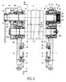
- FIG. 2 is a view in vertical and transverse section (relative to the ply), on a larger scale, taken along line II-II of FIG. 1.
- FIG. 3 is a sectional view, vertical and longitudinal (with respect to the sheet), taken along line III-III of FIG. 2.
- Figure 4 is an elevational view (taken from the right in Figure 2) of the front flange of the removable cassette.
- the offset printing apparatus which is shown in a simplified form in Figure 1, comprises a frame 1 consisting essentially of longitudinal and vertical uprights, parallel to each other, connected by cross members not shown and between which s' extend horizontally and transversely the different cylinders of the printing apparatus.
- the term “longitudinal” means parallel to the direction of travel of a web 2 to be printed passing through the apparatus, while the term “transverse” means "horizontal and perpendicular to the direction of travel of the web” or else "perpendicular to the plane of the drawing figure".
- the cylinders of the apparatus can be arranged vertically, being superimposed on each other, as shown in the drawing, or even horizontally or according to any other arrangement.
- this apparatus comprises an upper touch cylinder 3, mounted for rotation on the frame 1 of the apparatus and depositing a film of ink on a cylinder plate holder 4 arranged below it.
- This plate cylinder 4 is tangent to a lower blanket cylinder 5 and is mounted, together with this blanket cylinder 5, on a removable cassette 6.
- This cassette 6 essentially comprises two lateral, vertical and longitudinal flanges, namely a front flange 7 and a rear flange 8 braced by suitable horizontal crosspieces, not shown.
- the two flanges 7,8 constitute supports for respective shafts 9,10 of the plate 4 and blanket 5 cylinders 5.
- the assembly of the cassette 6 can be pulled, in the horizontal and transverse direction, outside the frame 1 of the printing device and set place inside this frame 1, for example by passing through an opening 1 a provided in the front upright of the frame 1.
- the printing apparatus comprises a counterpart cylinder 11, of axis transverse. It should be noted that, in certain devices allowing double-sided printing on the web 2, the counterpart cylinder 11 also constitutes a second blanket cylinder.
- the impression cylinder 11 is carried by a movable element vertically so as to be able to occupy a lowermost position indicated in phantom in Figure 1 and in which it is retracted below the lower edge of the opening 1a of the frame 1. In this retracted position the counterpart cylinder 11 allows the cassette 6 to be removed from the outside of the printing apparatus and reintroduced therein by a movement in the transverse direction. On the other hand, in the printing position, it is in the high position, as shown in FIG. 1, and it is tangent to the lower part of the blanket cylinder 5, the sheet to be printed 2 then being clamped between the two cylinders 5 and 11.
- the mobile assembly carrying the counterpart cylinder 11 can be constituted, for example, by a support oscillating around an axis 11a.
- the shaft 9 of the plate cylinder 4 is extended at its ends by front pins 9a and rear 9b housed respectively in front bearings 12 and rear 12a.
- the shaft 10 of the blanket cylinder 5 is extended at its ends by front pins 10a and rear 10b housed respectively in front bearings 13 and rear 13a.
- the two bearings 13, 13a supporting the shaft 10 of the blanket cylinder 5 are fixedly mounted respectively on the front flanges 7 and rear 8 of the cassette 6, while the bearings 12,12a supporting the shaft 9 of plate cylinder 4 are mounted adjustable on these flanges.
- each of the bearings 12, 12a of the shaft 9 comprises a bearing 14, for example with needles, in which the corresponding pin 9a, 9b is engaged and which is housed in an eccentric bore of a sleeve 15.
- This sleeve 15 is fixed at one end, by means of screws 16, to an operating collar 17 situated, for example, on the internal side of the corresponding flange 7.8. Because the bore of the sleeve 15 which receives the bearing 14, is eccentric relative to the axis of this sleeve 15, a rotation of the sleeve 15 about its axis causes a vertical displacement of the axis of the bearing 14, c that is to say of the shaft 9 of the plate cylinder 4.
- the assembly constituted by the sleeve 15 and its operating collar 17 will be considered subsequently as constituting an eccentric.
- the control of the rotational movement of this eccentric is carried out, on each of the flanges 7,8, by the same connection mechanism and we will now describe only, with particular reference to Figures 1 and 3, the connection mechanism 18 which is mounted on the rear flange 8 of the cassette and which controls the adjustment of the rear bearing 12a.
- This mechanism includes a vertical bar 19 which is mounted vertically movable and which extends close to the internal face of the rear flange 8, along one of its vertical edges.
- This operating bar 19 is designed to be actuated, at its lower end, by a control device provided on the frame of the printing apparatus, in order to lift it.
- the bar 19 may have, in its lower end portion, a notch 20 which can be coupled with an operating member forming part of the control device.
- the bar 19 is returned to the lower extreme position by a tension spring 21 which extends vertically and which is hooked, at its upper end, to a finger 22 secured to the bar 19 and, at its lower end, to a finger 23 fixed to the flange 8.
- This finger 23 is engaged through an oblong vertical slot 24 pierced in the bar 19, in order to limit the vertical movement of the latter.
- the operating bar 19 is articulated around an axis 25, on the end of a branch of a bent return lever 26 pivotally mounted on the flange 8, around a horizontal axis and transverse 27.
- the other branch of the bent lever 26 is articulated, about an axis 28, on one end of a substantially horizontal rod 29 whose other end is articulated, around an axis 31, on the lower part of the collar 17 forming part of the eccentric 15-17.
- the vertical operating bar 18 is shown in the extreme upper position in which it is raised by the control device of the printing apparatus and this position corresponds to a position of the eccentric 15-17 for which the axis from the landing 12a and consequently of the shaft 9 is in the extreme lower position.
- the operating bar 18 is no longer held raised, it is returned downwards by its return spring 21, which causes a rotation of the eccentric 15-17 and an offset of the axis of the bearing 14 and tree 9 upwards.
- the upper extreme position of the operating bar 19 and consequently the extreme rotational position of the eccentric 15-17 are determined by an adjustable stop 32 with adjusting screw 33.
- This adjustable stop 32 which determines the position set in pressure, is fixed on the internal face of the flange 8 and the adjusting screw is mounted in this stop so that its end is in contact with a bearing surface 34 provided in the lower part of the flange 17.
- One of the bearings of the shaft 9 of the plate cylinder 4, in the example described the front bearing 12, is furthermore somewhat adjustable in the horizontal and longitudinal direction, in order to allow adjustment of the bias between the two.
- cylinders 4 and 5 that is to say of the mutual inclination, in a horizontal plane, of their respective axes.
- the sleeve 15 of the eccentric 15-17 of the bearing 12a is itself housed in a second bearing 35, for example with needles, disposed inside an eccentric bore of a second sleeve 36 mounted at rotation, about its axis, in the front flange 7 by means of a third bearing 37.
- the sleeve 36 with an eccentric bore is integral with the outside of the front flange 7, of a flange 38 carrying an operating pin 39. Consequently, when the second sleeve 36 is rotated, the first movement is caused to move horizontally, in one direction or the other sleeve 15 and the journal 9a of the shaft 9, which thus makes it possible to adjust the bias of this shaft relative to the shaft 10 of the blanket cylinder 5.
- the two 4.5 rotating cylinders are driven at the rear of the device.
- the rear pins 9b, 10b of the two shafts 9 and 10 are respectively secured to two pinions 41 and 42, of the same pitch diameter, engaged with one another.
- one of the pinions 41, 42 in turn engages a drive pinion, not shown, which is rotatably mounted on the frame 1 of the printing apparatus and which is rotated by a general control device of the apparatus. Therefore the two plate cylinders 4 and blanket 5 are rotated in opposite directions to each other, at the same peripheral speed.
- the shaft 9 of the plate cylinder 4 is also mounted so that it can slide transversely to allow lateral adjustment of the plate plate that the cylinder 4 carries.
- the front journal 9a of the shaft 9 is subjected to the action of a compression spring 43 tending to push the shaft 9 towards the rear flange 8.
- This compression spring may advantageously consist of a stack of Belleville washers contained in a casing 44.
- the rear pin 9b of the shaft 9 is housed in rotation, by means of a bearing 45, in a thrust bearing 46 mounted at sliding in an opening of a casing 47 fixed outside the rear flange 8.
- the thrust bearing 46 is intended to cooperate with a movable adjustment arm, not shown, provided at the rear of the device. This arm therefore allows, by sliding more or less the thrust bearing 46 in the opening of the housing 47, to more or less push the shaft 9 forward and thus adjust the plate in the lateral direction.
Abstract
Description
La présente invention concerne un appareil d'impression offset.The present invention relates to an offset printing apparatus.
Les appareils d'impression offset comportent généralement un cylindre porte-plaque tangent à un cylindre blanchet, à couche superficielle souple, lequel reporte une couche d'encre sur une nappe de matériau à imprimer défilant entre le cylindre blanchet et un cylindre contrepartie appliqué sous pression contre le précédent, ce cylindre contrepartie pouvant être constitué par un cylindre blanchet dans le cas d'une impression recto-verso sur la nappe. Dans certains appareils le cylindre porte-plaque et le cylindre blanchet sont montés entre les deux flasques latéraux d'une cassette amovible pouvant être déplacée transversalement par rapport à l'appareil d'impression, c'est-à-dire perpendiculairement au sens de défilement de la nappe à imprimer.Offset printing machines generally include a plate cylinder tangent to a blanket cylinder, with a flexible surface layer, which transfers a layer of ink onto a sheet of printing material traveling between the blanket cylinder and a counterpart cylinder applied under pressure. against the previous one, this counterpart cylinder can be constituted by a blanket cylinder in the case of a double-sided printing on the web. In certain devices, the plate cylinder and the blanket cylinder are mounted between the two lateral flanges of a removable cassette that can be moved transversely relative to the printing apparatus, that is to say perpendicular to the direction of travel. of the tablecloth to print.
Dans ces appareils d'impression offset à cassette amovible, l'obtention des divers réglages nécessaires à l'impression est réalisée par le calage des cylindres soit à l'aide d'excentriques soit par l'application des cylindres sur des cales pentées. En règle générale le calage entre le cylindre porte-plaque et le cylindre blanchet est réalisé par un déplacement du cylindre blanchet, le biaisage, c'est-à-dire la faible inclinaison relative des axes des cylindres porte-plaque et blanchet, est réalisé par un déplacement du cylindre porte-plaque , et le calage entre le cylindre blanchet et le cylindre contrepartie (ou autre cylindre blanchet) est réalisé par le déplacement du cylindre contrepartie. Avec un tel type de montage, tous les cylindres doivent avoir une possibilité de déplacement pour permettre de réaliser les fonctions d'impression. Or on sait que, pour obtenir une impression de qualité, le cylindre blanchet doit être le plus rigide possible et pour ce faire on doit réaliser, en vue du déplacement du cylindre blanchet, des excentriques ayant des jeux de quelques micromètres et le plus souvent avec une alimentation d'un lubrifiant sous pression afin d'avoir une manoeuvre relativement aisée et une usure minimale dans le temps. Ce type de solution est donc relativement coûteux pour avoir une fonction d'impression correcte.In these offset cassette printing machines, the various settings necessary for printing are obtained by setting the cylinders either with the aid of eccentrics or by applying the cylinders to sloping wedges. In general, the setting between the plate cylinder and the blanket cylinder is carried out by a displacement of the blanket cylinder, biasing, that is to say the small relative inclination of the axes of the plate and blanket cylinders, is carried out by a movement of the plate cylinder, and the timing between the blanket cylinder and the counter cylinder (or other blanket cylinder) is achieved by the displacement of the counter cylinder. With such a type of assembly, all the cylinders must have a possibility of displacement to enable the printing functions to be performed. Now we know that, to obtain a quality impression, the blanket cylinder must be as rigid as possible and to do this we must produce, with a view to moving the blanket cylinder, eccentrics having clearances of a few micrometers and most often with a supply of a lubricant under pressure in order to have a relatively easy operation and minimal wear over time. This type of solution is therefore relatively expensive to have a correct printing function.
La présente invention vise à remédier à cet inconvénient en procurant un appareil d'impression offset du type à cassette amovible d'un coût global réduit du fait d'une grande simplification de son montage.The present invention aims to remedy this drawback by providing an offset printing device of the removable cassette type with a reduced overall cost due to a great simplification of its assembly.
A cet effet cet appareil d'impression offset comportant un bâti dans lequel peut être montée une cassette amovible portant un cylindre porte-plaque et un cylindre blanchet d'axes parallèles et tangents l'un à l'autre, une nappe à imprimer défilant entre le cylindre blanchet et un cylindre contrepartie, monté mobile sur le bâti de l'appareil et pouvant être appliqué contre le cylindre blanchet, les cylindres porte-plaque et blanchet étant engagés dans des paliers avant et dans des paliers arrière portés respectivement par des flasques avant et arrière de la cassette, est caractérisé en ce que les paliers du cylindre blanchet sont montés fixes sur les flasques de la cassette, en ce que les paliers du cylindre porte-plaque comprennent des moyens de réglage de la position de l'axe du cylindre porte-plaque et en ce que chacun des flasques avant et arrière de la cassette porte un mécanisme de liaison entre des moyens de commande mobiles de l'appareil d'impression et les moyens de réglage des paliers du cylindre porte-plaque, pour ajuster la position de l'axe de ce cylindre en fonction des conditions d'impression requises.To this end, this offset printing apparatus comprising a frame in which a removable cassette can be mounted carrying a plate cylinder and a blanket cylinder with axes parallel and tangent to one another, a tablecloth to be printed scrolling between the blanket cylinder and a counter cylinder, mounted movably on the frame of the apparatus and which can be applied against the blanket cylinder, the plate and blanket cylinders being engaged in front bearings and in rear bearings carried respectively by front flanges and rear of the cassette, is characterized in that the bearings of the blanket cylinder are fixedly mounted on the flanges of the cassette, in that the bearings of the plate cylinder include means for adjusting the position of the axis of the plate cylinder and in that each of the front and rear flanges of the cassette carries a connection mechanism between mobile control means of the printing apparatus and the means for adjusting the bearings of the plate cylinder, to adjust the position of the axis of this cylinder according to the printing conditions required.
On décrira ci-après, à titre d'exemple non limitatif, une forme d'exécution de la présente invention, en référence au dessin annexé sur lequel :An embodiment of the present invention will be described below, by way of non-limiting example, with reference to the appended drawing in which:
La figure 1 est une vue en élévation, schématique, avec arrachement partiel, d'un appareil d'impression offset suivant l'invention.Figure 1 is a schematic elevational view, partially broken away, of an offset printing apparatus according to the invention.
La figure 2 est une vue en coupe verticale et transversale (par rapport à la nappe), à plus grande échelle, faite suivant la ligne II-II de la figure 1.FIG. 2 is a view in vertical and transverse section (relative to the ply), on a larger scale, taken along line II-II of FIG. 1.
La figure 3 est une vue en coupe, verticale et longitudinale (par rapport à la nappe), faite suivant la ligne III-III de la figure 2.FIG. 3 is a sectional view, vertical and longitudinal (with respect to the sheet), taken along line III-III of FIG. 2.
La figure 4 est une vue en élévation (prise de la droite sur la figure 2) du flasque avant de la cassette amovible.Figure 4 is an elevational view (taken from the right in Figure 2) of the front flange of the removable cassette.
L'appareil d'impression offset suivant l'invention qui est représenté sous une forme simplifiée sur la figure 1, comprend un bâti 1 constitué essentiellement de montants longitudinaux et verticaux, parallèles entre eux, reliés par des traverses non représentées et entre lesquels s'étendent horizontalement et transversalement les différents cylindres de l'appareil d'impression. Dans la présente description, le terme "longitudinal" signifie parallèle au sens du défilement d'une nappe 2 à imprimer traversant l'appareil, tandis que le terme "transversal" signifie "horizontal et perpendiculaire au sens de défilement de la nappe" ou encore "perpendiculaire au plan de la figure du dessin".The offset printing apparatus according to the invention which is shown in a simplified form in Figure 1, comprises a
Les cylindres de l'appareil, d'axes parallèles et tangents entre eux, peuvent être disposés verticalement, en étant superposés les uns aux autres, comme il est représenté sur le dessin, ou encore horizontalement ou suivant toute autre disposition. Dans la forme d'exécution non limitative de l'appareil d'impression offset qui est représentée, cet appareil comprend un cylindre toucheur supérieur 3, monté à rotation sur le bâti 1 de l'appareil et déposant une pellicule d'encre sur un cylindre porte-plaque 4 disposé en-dessous de lui. Ce cylindre porte-plaque 4 est tangent à un cylindre blanchet inférieur 5 et est monté, conjointement avec ce cylindre blanchet 5, sur une cassette amovible 6. Cette cassette 6 comprend essentiellement deux flasques latéraux, verticaux et longitudinaux, à savoir un flasque avant 7 et un flasque arrière 8 entretoisés par des traverses horizontales appropriées non représentées. Les deux flasques 7,8 constituent des supports pour des arbres respectifs 9,10 des cylindres porte-plaque 4 et blanchet 5. L'ensemble de la cassette 6 peut être tiré, dans le sens horizontal et transversal, à l'extérieur du bâti 1 de l'appareil d'impression et mis en place à l'intérieur de ce bâti 1, par exemple en passant à travers une ouverture 1a prévue dans le montant avant du bâti 1. En dessous du cylindre blanchet 5 l'appareil d'impression comprend un cylindre contrepartie 11, d'axe transversal. Il y a lieu de noter que, dans certains appareils permettant une impression recto-verso sur la nappe 2, le cylindre contrepartie 11 constitue également un second cylindre blanchet. Ce cylindre contrepartie 11 est porté par un équipage mobile verticalement de manière à pouvoir occuper une position extrême inférieure qui est indiquée en trait mixte sur la figure 1 et dans laquelle il se trouve escamoté en dessous du bord inférieur de l'ouverture 1a du bâti 1. Dans cette position escamotée le cylindre contrepartie 11 permet l'extraction de la cassette 6 à l'extérieur de l'appareil d'impression et sa réintroduction dans celui-ci, par un mouvement dans le sens transversal. Par contre en position d'impression il se trouve en position haute, comme il est représenté sur la figure 1, et il est tangent à la partie inférieure du cylindre blanchet 5, la nappe à imprimer 2 étant alors serrée entre les deux cylindres 5 et 11. L'équipage mobile portant le cylindre contre-partie 11 peut être constitué, par exemple, par un support oscillant autour d'un axe 11a.The cylinders of the apparatus, with axes which are tangent to each other, can be arranged vertically, being superimposed on each other, as shown in the drawing, or even horizontally or according to any other arrangement. In the non-limiting embodiment of the offset printing apparatus which is represented, this apparatus comprises an
L'arbre 9 du cylindre porte-plaque 4 est prolongé, à ses extrémités, par des tourillons avant 9a et arrière 9b logés respectivement dans des paliers avant 12 et arrière 12a. De la même façon l'arbre 10 du cylindre blanchet 5 est prolongé, à ses extrémités, par des tourillons avant 10a et arrière 10b logés respectivement dans des paliers avant 13 et arrière 13a. Suivant l'invention les deux paliers 13, 13a supportant l'arbre 10 du cylindre blanchet 5 sont montés fixes respectivement sur les flasques avant 7 et arrière 8 de la cassette 6, alors que, les paliers 12,12a supportant l'arbre 9 du cylindre porte-plaque 4 sont montés réglables sur ces flasques. A cet effet chacun des paliers 12,12a de l'arbre 9 comprend un roulement 14, par exemple à aiguilles, dans lequel est engagé le tourillon correspondant 9a,9b et qui est logé dans un alésage excentré d'un manchon 15. Ce manchon 15 est fixé à une extrémité, au moyen de vis 16, à une collerette de manoeuvre 17 située, par exemple, du côté interne du flasque 7,8 correspondant. Du fait que l'alésage du manchon 15 qui reçoit le roulement 14, est excentré par rapport à l'axe de ce manchon 15, une rotation du manchon 15 autour de son axe entraîne un déplacement vertical de l'axe du roulement 14, c'est-à-dire de l'arbre 9 du cylindre porte-plaque 4.The
L'ensemble constitué par le manchon 15 et sa collerette de manoeuvre 17 sera considéré par la suite comme constituant un excentrique. La commande du mouvement de rotation de cet excentrique est réalisée, sur chacun des flasques 7,8, par un même mécanisme de liaison et on décrira maintenant uniquement, en se référant plus particulièrement aux figures 1 et 3, le mécanisme de liaison 18 qui est monté sur le flasque arrière 8 de la cassette et qui commande le réglage du palier arrière 12a. Ce mécanisme comprend une barre verticale 19 qui est montée mobile verticalement et qui s'étend à proximité de la face interne du flasque arrière 8, le long de l'un de ses bords verticaux. Cette barre de manoeuvre 19 est prévue pour être actionnée, à son extrémité inférieure, par un dispositif de commande prévu sur le bâti de l'appareil d'impression, afin de la soulever. A cet effet la barre 19 peut présenter, dans sa partie extrême inférieure, une encoche 20 pouvant s'accoupler avec un organe de manoeuvre faisant partie du dispositif de commande. La barre 19 est rappelée en position extrême inférieure par un ressort de traction 21 qui s'étend verticalement et qui est accroché, à son extrémité supérieure, à un doigt 22 solidaire de la barre 19 et, à son extrémité inférieure, à un doigt 23 fixé au flasque 8. Ce doigt 23 est engagé à travers une lumière oblongue verticale 24 percée dans la barre 19, afin de limiter le mouvement vertical de celle-ci. A son extrémité supérieure la barre de manoeuvre 19 est articulée, autour d'un axe 25, sur l'extrémité d'une branche d'un levier de renvoi coudé 26 monté à pivotement sur le flasque 8, autour d'un axe horizontal et transversal 27. L'autre branche du levier coudé 26 est articulée, autour d'un axe 28, sur une extrémité d'une bielle sensiblement horizontale 29 dont l'autre extrémité est articulée, autour d'un axe 31, sur la partie inférieure de la collerette 17 faisant partie de l'excentrique 15-17. La barre verticale de manoeuvre 18 est représentée en position extrême supérieure dans laquelle elle se trouve être soulevée par le dispositif de commande de l'appareil d'impression et cette position correspond à une position de l'excentrique 15-17 pour laquelle l'axe du palier 12a et par conséquent de l'arbre 9 se trouve en position extrême inférieure. Lorsque la barre de manoeuvre 18 n'est plus maintenue soulevée, elle est rappelée vers le bas par son ressort de rappel 21, ce que entraîne une rotation de l'excentrique 15-17 et un décalage de l'axe du roulement 14 et de l'arbre 9 vers le haut.The assembly constituted by the
La position extrême supérieure de la barre de manoeuvre 19 et par conséquent la position extrême en rotation de l'excentrique 15-17 sont déterminées par une butée réglable 32 à vis de réglage 33. Cette butée réglable 32 qui détermine la position calée en pression, est fixée sur la face interne du flasque 8 et la vis de réglage est montée dans cette butée de manière que son extrémité soit en contact avec une surface d'appui 34 prévue dans la partie inférieure de la collerette 17.The upper extreme position of the
L'un des paliers de l'arbre 9 du cylindre porte-plaque 4, dans l'exemple décrit le palier avant 12, est en outre réglable quelque peu dans la direction horizontale et longitudinale, afin de permettre un réglage du biais entre les deux cylindres 4 et 5, c'est-à-dire de l'inclinaison mutuelle, dans un plan horizontal, de leurs axes respectifs. A cet effet le manchon 15 de l'excentrique 15-17 du palier 12a est lui-même logé dans un deuxième roulement 35, par exemple à aiguilles, disposé à l'intérieur d'un alésage excentré d'un second manchon 36 monté à rotation, autour de son axe, dans le flasque avant 7 par l'intermédiaire d'un troisième roulement 37. Le manchon 36 à alésage excentré est solidaire, à l'extérieur du flasque avant 7, d'une collerette 38 portant un téton de manoeuvre 39. Par conséquent lorsque l'on fait tourner le second manchon 36, on provoque un déplacement horizontal, dans un sens ou dans l'autre, du premier manchon 15 et du tourillon 9a de l'arbre 9, ce qui permet ainsi de régler le biais de cet arbre par rapport à l'arbre 10 du cylindre blanchet 5.One of the bearings of the
L'entrainement des deux cylindres 4,5 en rotation s'effectue à l'arrière de l'appareil. A cet effet les tourillons arrière 9b,10b des deux arbres 9 et 10 sont respectivement solidaires de deux pignons 41 et 42, de même diamètre primitif, en prise l'un avec l'autre. Lorsque la cassette 6 est engagée dans le bâti 1 de l'appareil d'impression, l'un des pignons 41,42 vient à son tour en prise avec un pignon d'entraînement, non représenté, qui est monté à rotation sur le bâti 1 de l'appareil d'impression et qui est entraîné en rotation par un dispositif de commande générale de l'appareil. De ce fait les deux cylindres porte-plaque 4 et blanchet 5 sont entraînés en rotation en sens inverse l'un de l'autre, à la même vitesse périphérique.The two 4.5 rotating cylinders are driven at the rear of the device. To this end, the
Comme on peut le voir sur la figure 2, l'arbre 9 du cylindre porte-plaque 4 est également monté de manière à pouvoir coulisser transversalement afin de permettre un réglage latéral de la plaque-cliché que le cylindre 4 porte. A cet effet le tourillon avant 9a de l'arbre 9 est soumis à l'action d'un ressort de compression 43 tendant à repousser l'arbre 9 en direction du flasque arrière 8. Ce ressort de compression peut être avantageusement constitué par un empilage de rondelles Belleville contenues dans un carter 44. Par ailleurs le tourillon arrière 9b de l'arbre 9 est logé à rotation, par l'intermédiaire d'un roulement 45, dans un palier de poussée 46 monté à coulissement dans une ouverture d'un carter 47 fixé à l'extérieur du flasque arrière 8. Le palier de poussée 46 est destiné à coopérer avec un bras de réglage mobile, non représenté, prévu à l'arrière de l'appareil. Ce bras permet par conséquent, en faisant coulisser plus ou moins le palier de poussée 46 dans l'ouverture du carter 47, de repousser plus ou moins l'arbre 9 vers l'avant et de régler ainsi la plaque dans le sens latéral.As can be seen in Figure 2, the
Claims (8)
Applications Claiming Priority (2)
| Application Number | Priority Date | Filing Date | Title |
|---|---|---|---|
| FR929204114A FR2689448B1 (en) | 1992-04-03 | 1992-04-03 | OFFSET PRINTING APPARATUS. |
| FR9204114 | 1992-04-03 |
Publications (2)
| Publication Number | Publication Date |
|---|---|
| EP0564372A1 true EP0564372A1 (en) | 1993-10-06 |
| EP0564372B1 EP0564372B1 (en) | 1996-10-16 |
Family
ID=9428478
Family Applications (1)
| Application Number | Title | Priority Date | Filing Date |
|---|---|---|---|
| EP93400869A Expired - Lifetime EP0564372B1 (en) | 1992-04-03 | 1993-04-02 | Offset printing machine |
Country Status (4)
| Country | Link |
|---|---|
| US (1) | US5272974A (en) |
| EP (1) | EP0564372B1 (en) |
| DE (1) | DE69305404T2 (en) |
| FR (1) | FR2689448B1 (en) |
Families Citing this family (8)
| Publication number | Priority date | Publication date | Assignee | Title |
|---|---|---|---|---|
| US5706728A (en) * | 1996-07-30 | 1998-01-13 | Rdp Marathon Inc. | Printing apparatus |
| DE19849633A1 (en) * | 1998-10-28 | 2000-05-04 | Heidelberger Druckmasch Ag | Positioning device in a printing press |
| DE19943027C5 (en) * | 1998-10-28 | 2016-11-17 | Heidelberger Druckmaschinen Ag | Positioning device in a printing machine |
| US20080236419A1 (en) * | 2005-08-30 | 2008-10-02 | Jose Betes Peruga | Roller Cassette for Semi-Rotary Machines, Which Can Be Inserted Into Offset Printing Units |
| JP4878854B2 (en) * | 2006-01-31 | 2012-02-15 | 三菱重工印刷紙工機械株式会社 | Printer |
| EP1950037A3 (en) * | 2007-01-25 | 2009-12-23 | Komori Corporation | Switch-Over Processing Method And apparatus |
| US20110132216A1 (en) * | 2009-12-09 | 2011-06-09 | 7242514 Canada Inc. | Stack angle compensation arrangement for a skewing adjustment system in an offset printing press |
| US9492995B2 (en) * | 2012-11-06 | 2016-11-15 | Lg Chem, Ltd. | Roll printing machine and method of roll printing using same |
Citations (2)
| Publication number | Priority date | Publication date | Assignee | Title |
|---|---|---|---|---|
| FR2391073A1 (en) * | 1977-05-17 | 1978-12-15 | Polygraph Leipzig | Plate cylinder with bearing in eccentric sleeve - has push=pull rod with toothed part for diagonal adjustment |
| EP0095423A1 (en) * | 1982-05-25 | 1983-11-30 | MACHINES CHAMBON Société anonyme dite: | Variable-size offset printing apparatus |
Family Cites Families (7)
| Publication number | Priority date | Publication date | Assignee | Title |
|---|---|---|---|---|
| US913119A (en) * | 1908-03-23 | 1909-02-23 | Fuchs And Lang Mfg Company | Throw-out mechanism. |
| US1231932A (en) * | 1914-05-15 | 1917-07-03 | Corp Of Maschinenfabrik Johannisberg G M B H | Rotary printing or embossing machine. |
| US1330793A (en) * | 1916-04-04 | 1920-02-17 | Gustav A Friess | Cylinder-adjusting mechanism for printing-presses |
| US1816796A (en) * | 1930-01-16 | 1931-07-28 | Firm Rock Stroh Werke Ag | Rotary offset printing machine |
| DE1436541A1 (en) * | 1964-04-02 | 1969-02-06 | Roland Offsetmaschf | Web-fed rotary printing press |
| US4458590A (en) * | 1982-09-30 | 1984-07-10 | Harris Graphics Corporation | Printing press with plate cylinder skew and throw off |
| US5186103A (en) * | 1992-06-12 | 1993-02-16 | Man Roland Druckmaschinen Ag | Printing machine system, especially for printing on a web of heavy or thick stock material, with interchangeable printing cylinders |
-
1992
- 1992-04-03 FR FR929204114A patent/FR2689448B1/en not_active Expired - Fee Related
-
1993
- 1993-04-01 US US08/041,482 patent/US5272974A/en not_active Expired - Fee Related
- 1993-04-02 EP EP93400869A patent/EP0564372B1/en not_active Expired - Lifetime
- 1993-04-02 DE DE69305404T patent/DE69305404T2/en not_active Expired - Fee Related
Patent Citations (2)
| Publication number | Priority date | Publication date | Assignee | Title |
|---|---|---|---|---|
| FR2391073A1 (en) * | 1977-05-17 | 1978-12-15 | Polygraph Leipzig | Plate cylinder with bearing in eccentric sleeve - has push=pull rod with toothed part for diagonal adjustment |
| EP0095423A1 (en) * | 1982-05-25 | 1983-11-30 | MACHINES CHAMBON Société anonyme dite: | Variable-size offset printing apparatus |
Also Published As
| Publication number | Publication date |
|---|---|
| FR2689448A1 (en) | 1993-10-08 |
| US5272974A (en) | 1993-12-28 |
| DE69305404D1 (en) | 1996-11-21 |
| FR2689448B1 (en) | 1994-06-24 |
| DE69305404T2 (en) | 1997-05-15 |
| EP0564372B1 (en) | 1996-10-16 |
Similar Documents
| Publication | Publication Date | Title |
|---|---|---|
| EP0095423B1 (en) | Variable-size offset printing apparatus | |
| EP0390689B1 (en) | Rotating cutter apparatus | |
| EP0853527B1 (en) | Device for measuring or checking an orbitally mobile cylindrical part during machining thereof | |
| EP0177391B1 (en) | Screen printing machine | |
| EP0329237A1 (en) | Silk screen printing machine | |
| EP0564372B1 (en) | Offset printing machine | |
| EP0611240B1 (en) | Printing machine, incorporating at least one double-displacement cylinder | |
| FR2743548A1 (en) | MECHANISM WITH TRACTOR SUCTION ELEMENTS, IN PARTICULAR FOR A DEVICE FOR CORRECTING THE OBLESSITY OF SHEETS | |
| FR2557504A1 (en) | PAPER SOURCE DEVICE FOR VERSO-SIDED PRINTING | |
| CH630291A5 (en) | ROTARY PRINTER FOR MULTI-COLOR PRINTING ON SHEETS SUSTAINED IN A CONTINUOUS WAY. | |
| EP0298056A2 (en) | Bending press for sheets | |
| CH632022A5 (en) | WEAVING MACHINE WITH DEVICE AVOIDING DIFFERENCES IN DUITING AT THE START OF THE MACHINE. | |
| CH670989A5 (en) | ||
| FR2726787A1 (en) | DEVICE FOR SUPPORTING A CAVITY SQUEEGEE FOR AN INK GROUP OF A PRINTING ROTARY | |
| CH689717A5 (en) | Flexible printing plate positioner for rotary printing machine | |
| EP0260178B1 (en) | Printing machine for printing on convex surfaces | |
| FR2647386A1 (en) | Device for marking out and partially cutting through the thickness of a protected adhesive multi-layer complex and machine making use thereof | |
| EP0195727B1 (en) | Inking unit with independently adjustable ink measuring sections | |
| EP0611187B1 (en) | Rotary cutting device | |
| EP0564360B1 (en) | Offset printing machine | |
| EP0429317B1 (en) | Printing press with controlled elevation of the printing unit | |
| EP0081614B1 (en) | Automatic silk screen printing machine comprising a squeegee-lowering device actuated by an electro-magnet | |
| EP0730954A1 (en) | Screen printing machine with changeable squeegee | |
| LU82643A1 (en) | DEVICE FOR ADJUSTING AN INKWAY FOR A ROTARY OFFSET PRINTER | |
| FR2593157A1 (en) | PRESS ROLL DEVICE FOR A DRIVE SYSTEM OF A PRINTING MEDIUM ON A PRINTING MACHINE. |
Legal Events
| Date | Code | Title | Description |
|---|---|---|---|
| PUAI | Public reference made under article 153(3) epc to a published international application that has entered the european phase |
Free format text: ORIGINAL CODE: 0009012 |
|
| AK | Designated contracting states |
Kind code of ref document: A1 Designated state(s): CH DE GB IT LI NL SE |
|
| 17P | Request for examination filed |
Effective date: 19940323 |
|
| 17Q | First examination report despatched |
Effective date: 19951006 |
|
| GRAH | Despatch of communication of intention to grant a patent |
Free format text: ORIGINAL CODE: EPIDOS IGRA |
|
| GRAH | Despatch of communication of intention to grant a patent |
Free format text: ORIGINAL CODE: EPIDOS IGRA |
|
| GRAH | Despatch of communication of intention to grant a patent |
Free format text: ORIGINAL CODE: EPIDOS IGRA |
|
| GRAH | Despatch of communication of intention to grant a patent |
Free format text: ORIGINAL CODE: EPIDOS IGRA |
|
| GRAA | (expected) grant |
Free format text: ORIGINAL CODE: 0009210 |
|
| AK | Designated contracting states |
Kind code of ref document: B1 Designated state(s): CH DE GB IT LI NL SE |
|
| REF | Corresponds to: |
Ref document number: 69305404 Country of ref document: DE Date of ref document: 19961121 |
|
| ITF | It: translation for a ep patent filed |
Owner name: STUDIO TORTA SOCIETA' SEMPLICE |
|
| GBT | Gb: translation of ep patent filed (gb section 77(6)(a)/1977) |
Effective date: 19970115 |
|
| PLBE | No opposition filed within time limit |
Free format text: ORIGINAL CODE: 0009261 |
|
| STAA | Information on the status of an ep patent application or granted ep patent |
Free format text: STATUS: NO OPPOSITION FILED WITHIN TIME LIMIT |
|
| 26N | No opposition filed | ||
| PGFP | Annual fee paid to national office [announced via postgrant information from national office to epo] |
Ref country code: GB Payment date: 20010316 Year of fee payment: 9 |
|
| PGFP | Annual fee paid to national office [announced via postgrant information from national office to epo] |
Ref country code: NL Payment date: 20010329 Year of fee payment: 9 |
|
| PGFP | Annual fee paid to national office [announced via postgrant information from national office to epo] |
Ref country code: SE Payment date: 20010402 Year of fee payment: 9 |
|
| REG | Reference to a national code |
Ref country code: GB Ref legal event code: IF02 |
|
| PG25 | Lapsed in a contracting state [announced via postgrant information from national office to epo] |
Ref country code: GB Free format text: LAPSE BECAUSE OF NON-PAYMENT OF DUE FEES Effective date: 20020402 |
|
| PG25 | Lapsed in a contracting state [announced via postgrant information from national office to epo] |
Ref country code: SE Free format text: LAPSE BECAUSE OF NON-PAYMENT OF DUE FEES Effective date: 20020403 |
|
| PG25 | Lapsed in a contracting state [announced via postgrant information from national office to epo] |
Ref country code: NL Free format text: LAPSE BECAUSE OF NON-PAYMENT OF DUE FEES Effective date: 20021101 |
|
| EUG | Se: european patent has lapsed |
Ref document number: 93400869.9 |
|
| GBPC | Gb: european patent ceased through non-payment of renewal fee |
Effective date: 20020402 |
|
| NLV4 | Nl: lapsed or anulled due to non-payment of the annual fee |
Effective date: 20021101 |
|
| PG25 | Lapsed in a contracting state [announced via postgrant information from national office to epo] |
Ref country code: IT Free format text: LAPSE BECAUSE OF NON-PAYMENT OF DUE FEES;WARNING: LAPSES OF ITALIAN PATENTS WITH EFFECTIVE DATE BEFORE 2007 MAY HAVE OCCURRED AT ANY TIME BEFORE 2007. THE CORRECT EFFECTIVE DATE MAY BE DIFFERENT FROM THE ONE RECORDED. Effective date: 20050402 |
|
| PGFP | Annual fee paid to national office [announced via postgrant information from national office to epo] |
Ref country code: CH Payment date: 20070413 Year of fee payment: 15 |
|
| PGFP | Annual fee paid to national office [announced via postgrant information from national office to epo] |
Ref country code: DE Payment date: 20070423 Year of fee payment: 15 |
|
| REG | Reference to a national code |
Ref country code: CH Ref legal event code: PL |
|
| PG25 | Lapsed in a contracting state [announced via postgrant information from national office to epo] |
Ref country code: LI Free format text: LAPSE BECAUSE OF NON-PAYMENT OF DUE FEES Effective date: 20080430 Ref country code: DE Free format text: LAPSE BECAUSE OF NON-PAYMENT OF DUE FEES Effective date: 20081101 Ref country code: CH Free format text: LAPSE BECAUSE OF NON-PAYMENT OF DUE FEES Effective date: 20080430 |