EP0564217A1 - Power driven hammer drill - Google Patents
Power driven hammer drill Download PDFInfo
- Publication number
- EP0564217A1 EP0564217A1 EP93302437A EP93302437A EP0564217A1 EP 0564217 A1 EP0564217 A1 EP 0564217A1 EP 93302437 A EP93302437 A EP 93302437A EP 93302437 A EP93302437 A EP 93302437A EP 0564217 A1 EP0564217 A1 EP 0564217A1
- Authority
- EP
- European Patent Office
- Prior art keywords
- housing
- hammer drill
- power driven
- driven hammer
- electric motor
- Prior art date
- Legal status (The legal status is an assumption and is not a legal conclusion. Google has not performed a legal analysis and makes no representation as to the accuracy of the status listed.)
- Granted
Links
Images


Classifications
-
- B—PERFORMING OPERATIONS; TRANSPORTING
- B25—HAND TOOLS; PORTABLE POWER-DRIVEN TOOLS; MANIPULATORS
- B25D—PERCUSSIVE TOOLS
- B25D17/00—Details of, or accessories for, portable power-driven percussive tools
-
- B—PERFORMING OPERATIONS; TRANSPORTING
- B25—HAND TOOLS; PORTABLE POWER-DRIVEN TOOLS; MANIPULATORS
- B25D—PERCUSSIVE TOOLS
- B25D2211/00—Details of portable percussive tools with electromotor or other motor drive
- B25D2211/06—Means for driving the impulse member
- B25D2211/061—Swash-plate actuated impulse-driving mechanisms
-
- B—PERFORMING OPERATIONS; TRANSPORTING
- B25—HAND TOOLS; PORTABLE POWER-DRIVEN TOOLS; MANIPULATORS
- B25D—PERCUSSIVE TOOLS
- B25D2222/00—Materials of the tool or the workpiece
- B25D2222/54—Plastics
- B25D2222/61—Polyamides, e.g. Nylon
-
- B—PERFORMING OPERATIONS; TRANSPORTING
- B25—HAND TOOLS; PORTABLE POWER-DRIVEN TOOLS; MANIPULATORS
- B25D—PERCUSSIVE TOOLS
- B25D2250/00—General details of portable percussive tools; Components used in portable percussive tools
- B25D2250/065—Details regarding assembling of the tool
-
- B—PERFORMING OPERATIONS; TRANSPORTING
- B25—HAND TOOLS; PORTABLE POWER-DRIVEN TOOLS; MANIPULATORS
- B25D—PERCUSSIVE TOOLS
- B25D2250/00—General details of portable percussive tools; Components used in portable percussive tools
- B25D2250/191—Ram catchers for stopping the ram when entering idling mode
-
- B—PERFORMING OPERATIONS; TRANSPORTING
- B25—HAND TOOLS; PORTABLE POWER-DRIVEN TOOLS; MANIPULATORS
- B25D—PERCUSSIVE TOOLS
- B25D2250/00—General details of portable percussive tools; Components used in portable percussive tools
- B25D2250/331—Use of bearings
-
- B—PERFORMING OPERATIONS; TRANSPORTING
- B25—HAND TOOLS; PORTABLE POWER-DRIVEN TOOLS; MANIPULATORS
- B25D—PERCUSSIVE TOOLS
- B25D2250/00—General details of portable percussive tools; Components used in portable percussive tools
- B25D2250/331—Use of bearings
- B25D2250/335—Supports therefor
Abstract
Description
- The present invention relates to an internal structure of a power driven hammer drill, and more specifically to an intermediate housing disposed between a gear housing and a motor housing.
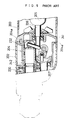
- A power driven hammer drill generally includes an intermediate housing arranged between a gear housing and a motor housing as disclosed in Japanese Utility Model Laying-Open Gazette No. 61-172786 by the applicant of the present invention. Fig. 9 schematically shows a typical example of such conventional power driven hammer drills. The hammer drill includes an
intermediate housing 204 positioned between agear housing 202 and amotor housing 203. Theintermediate housing 204 consists of abearing member 241 for supporting anarmature shaft 206 of amotor 205 and anintermediate shaft 207 and separating apiston cylinder 232 from themotor 205, and a cylindricalpiston housing member 242 protruded from thebearing member 241 for supporting a rotatingtool holder 230 and a reciprocatingpiston cylinder 232. - The intermediate housing is required to have sufficient strength and durability, and is generally composed of a metal such as aluminum as disclosed in UK Patent Application GB 2085345.
- In the conventional metal intermediate housing described above, the
bearing member 241 and thepiston housing member 242 are separately manufactured and assembled later, which increases both the cost and labor and makes the hammer drill undesirably heavy. Metalouter faces 204a of theintermediate housing 204 exposed to the atmosphere may cause electric shocks. - Another structure of an intermediate housing is disclosed in UK Patent Application GB 2085345, in which a bearing member and a piston housing member are integrally composed of aluminum. The metal intermediate housing of this structure also makes the hammer drill undesirably heavy, prevents smooth operation of the hammer drill, and requires excessive work machining bores and holes, which increase the manufacturing cost and labor. Inside the aluminum housing member is generally covered with iron or another metal to improve the durability, which further increases the manufacturing cost. The metal intermediate housing is accommodated in a plastic housing to prevent possible electric shocks, which enlarges the outer diameter of the hammer drill.
- One object of the invention is thus to provide an improved power driven hammer drill which is light in weight and easily and safely handled.
- Another object of the invention is to provide a power driven hammer drill including an intermediate housing which can be manufactured cost-effectively through relatively simple steps
- Still another object of the invention is to provide a power riven hammer drill including an intermediate housing which is free from thermal deformation even in continuous operation.
- The above and other related objects are realized by a power driven hammer drill of the invention, which includes:
an electric motor; a tool holder for supporting a tool bit and transmitting a rotation of the electric motor to the tool bit via a driving mechanism including an armature shaft of the electric motor, plural gear elements, and an intermediate shaft; a piston cylinder slidably movable along an axis of the power driven hammer drill; an air cushion percussive mechanism for converting a rotary movement of the electric motor to a reciprocating movement of the piston cylinder and transmitting the reciprocating movement to the tool bit as an axial impact force; and an externally accessible switching mechanism for switching off the air cushion percussive mechanism. - The power driven hammer drill of the invention further includes an intermediate housing disposed between a gear housing and a motor housing. The intermediate housing consists of a bearing member for supporting the armature shaft of the electric motor and the intermediate shaft, and a cylindrical piston housing member for holding the tool holder and the piston cylinder. The bearing member and the cylindrical piston housing member of the intermediate housing are integrally composed of a synthetic resin.
- The synthetic resin used in the invention has desirable mechanical properties including high tenacity and excellent heat resistance and wear resistance: for example, a glass fiber-reinforced polyamide resin.
- The intermediate housing further includes a plurality of ribs radially and integrally protruding from an outer face of the cylindrical piston housing member, the plurality of ribs facing to an inner wall of the gear housing with a little space held therebetween.
- The intermediate housing of the invention is integrally composed of a synthetic resin. This structure efficiently saves labor and cost required for manufacturing a conventional intermediate housing composed of a metal, and reduces the weight of the power driven hammer drill. The synthetic resin of the outer-most part of the intermediate housing exposed to the atmosphere effectively prevents electric shocks and allows easy and safe operation of the power driven hammer drill. The plurality of ribs attached to the piston housing member give a sufficient strength durable to a stress applied onto the intermediate housing in operation of the power driven hammer drill.
- In another aspect of this invention, a power driven hammer drill includes: an electric motor; a fan for cooling the electric motor; a tool holder for supporting a tool bit and transmitting a rotation of the electric motor to the tool bit via a driving mechanism comprising an armature shaft of the electric motor, plural gear elements, and an intermediate shaft; a piston cylinder slidably movable along an axis of the power driven hammer drill; an air cushion percussive mechanism for converting a rotary movement of the electric motor to a reciprocating movement of the piston cylinder and transmitting the reciprocating movement to the tool bit as an axial impact force; and an externally accessible switching mechanism for switching off the air cushion percussive mechanism.
- The power driven hammer drill further includes an intermediate housing disposed between a gear housing and a motor housing. The intermediate housing consists of a bearing member for separating the gear housing from the motor housing and supporting the armature shaft of the electric motor and the intermediate shaft, and a cylindrical piston housing member protruded from the bearing member for holding the tool holder and the piston cylinder. The bearing member has at least one opening for feeding an air flow generated by the fan to the cylindrical piston housing member, and the cylindrical piston housing member has at least one air conduit for circulating the air flow fed through the opening.
- At least one thicker wall portion having a hollow inside thereof is attached to an outer face of the piston housing member. The hollow connects with the opening of the bearing member and includes an air inlet, an air outlet separated from the air inlet by a partition plate, and an intermediate opening to form a U-shaped air conduit for circulating the air flow.
- The air flow generated by the fan enters the hollow formed in the thicker wall portion through the opening of the bearing member. The air flow circulates in the thicker wall portion and continuously cools the cylindrical piston housing member to prevent overheat of the piston housing member and the bearing member. This structure of the invention efficiently prevents thermal deformation of the piston housing member in continuous operation of the power driven hammer drill.
- In this structure, the bearing member and the cylindrical piston housing member of the intermediate housing may be integrally composed of a synthetic resin, which has excellent mechanical properties including high tenacity, heat resistance, and wear resistance.
- Embodiments of the invention will now be described by way of example only with reference to the accompanying drawings, in which:
- Fig. 1 is a partially sectional view showing a power driven hammer drill embodying the invention;
- Fig. 2 is a perspective view showing one structure of an intermediate housing as a first embodiment of the invention;
- Fig. 3 is a cross sectional view showing the intermediate housing of Fig. 2 taken on the line of III-III of Fig. 1;
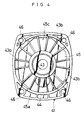
- Fig. 4 is a bottom view illustrating the intermediate housing of the first embodiment;
- Fig. 5 is a perspective view showing another structure of an intermediate housing as a second embodiment of the invention;
- Fig. 6 is a cross sectional view showing the intermediate housing of Fig. 5 taken on the same position as Fig. 3;
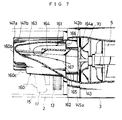
- Fig. 7 shows the air flow in the intermediate housing of the second embodiment;
- Fig. 8 is a bottom view illustrating the intermediate housing of the second embodiment; and
- Fig. 9 is a sectional view showing an intermediate housing used in a conventional power driven hammer drill.
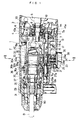
- Fig. 1 is a partially sectional view showing a power driven hammer drill 1 embodying the invention. In the power driven hammer drill 1, rotation of a
motor 5 is transmitted to anintermediate shaft 7 via amotor pinion 6a of anarmature shaft 6 and afirst gear element 13 and then to athird gear element 36 engaging with apinion 27a of asecond gear element 27 of theintermediate shaft 7 so as to rotate a tool bit B via atool holder 30. The rotary movement of theintermediate shaft 7 is further transmitted via aclutch mechanism 20 to aboss member 15, which, in cooperation with awobble arm 18, converts the rotary movement to an axially reciprocating movement of apiston cylinder 32. The reciprocating movement of thepiston cylinder 32 generates a likewise axial to-and-fro movement of astriker 34 through an air cushion formed between anair chamber 33 and thestriker 34, and is finally transmitted via apercussive element 31 to the tool bit B as an axial impact force. - In the above power driven hammer drill 1, an
intermediate housing 4 is bolted between agear housing 2 and amotor housing 3 as clearly seen in Fig. 1. Theintermediate housing 4 consists of a bearingmember 41 for supporting thearmature shaft 6 and theintermediate shaft 7, and a cylindricalpiston housing member 42 for holding thetool holder 30 and thepiston cylinder 32. Thebearing member 41 and the cylindricalpiston housing member 42 are integrally composed of a glass fiber-reinforced polyamide resin, which has desirable mechanical properties including high tenacity and excellent heat resistance and wear resistance. Thebearing member 41 has, on its approximate center, a first bearingseat 43 for accommodating a ball bearing 9 and anoil seal 10 for supporting thearmature shaft 6 via a washer 8. Thebearing member 41 also has a second bearingseat 44 arranged below the first bearingseat 43. The second bearingseat 44 supports oneend 7a of theintermediate shaft 7 through function of a needle bearing 11. Theother end 7b of thearmature shaft 7 is inserted into a bore 2b of thegear housing 2 and pressed against the second bearingseat 44 by aspring 12b via a ball 12a. This structure efficiently reduces uncomfortable vibration and noise due to rotation of theintermediate shaft 7 in operation of the power driven hammer drill 1. - The
first gear element 13 engages with themotor pinion 6a of thearmature shaft 6 and is fixed with akey 14. Theintermediate shaft 7 is idlingly fitted in theboss member 15, which hascircumferential grooves 15a for supporting a pivotablymovable ring 17 via a plurality ofballs 16. Thewobble arm 18 is integrally formed with and protrudes from thering 17. Theboss member 15 is further provided withfirst engagement claws 19, which are arranged opposite to second engagement claws 28 formed on thesecond gear element 27 positioned across theclutch mechanism 20 from theboss member 15. - The
clutch mechanism 20 includes an axiallyslidable clutch 22, which is coupled with theintermediate shaft 7 by a spline structure and has atrack 21 on the circumference thereof, and aneccentric pin 23 fitted into thetrack 21. Theclutch 22 has, on both ends thereof,first clutch teeth 22a and second clutch teeth 22b which respectively engage with thefirst engagement claws 19 of theboss member 15 and the second engagement claws 28 of thesecond gear element 27. The axially sliding movement of theclutch 22 is defined between theboss member 15 and thesecond gear element 27 by engagement of first orsecond clutch teeth 22a or 22b with thefirst engagement claws 19 or the second engagement claws 28. Ahead 23a of theeccentric pin 23 is inserted into thetrack 21 in a direction perpendicular to theintermediate shaft 7, and is held in apin seat 25 by aneedle bearing 24. Abody 23b of theeccentric pin 23 is rotatably fixed to a switchinglever 26. - As clearly seen in Fig. 1, the cylindrical
piston housing member 42 of theintermediate housing 4 holds thetool holder 30 which is supported by aball bearing 29 on its forward (leftward in Fig. 1) portion. One end 42a of thepiston housing member 42 is in contact with acushion washer 30c. Thetool holder 30 supports the slidably movingpercussive element 31 in the forward portion thereof, and the slidably movingpiston cylinder 32, which is coupled with thewobble arm 18 via apiston pin 18a, in the rear portion thereof. Theair chamber 33 and the slidably movingstriker 34 are disposed in thepiston cylinder 32. - A rotary movement of the
motor 5 is transmitted to thetool holder 30 via thethird gear element 36 which is idlingly attached to outside of thetool holder 30. Thethird gear element 36 engages with thepinion 27a of thesecond gear element 27 and is pressed backward (rightward in Fig. 1) by aspring 37 fixed to awasher 35. A rear face 36a of thethird gear element 36 includes a firstclutch face 36b engaging with a second clutch face 30b formed on a front side wall of aflange 30a on a rear end of thetool holder 30. When an excessive load of the tool bit B is applied onto thetool holder 30, the firstclutch face 36b of thethird gear element 36 is disengaged from the second clutch face 30b of thetool holder 30 to race thethird gear element 36. - Structure of the
intermediate housing 4 is further described in detail based on the perspective view of Fig. 2, the cross sectional view of Fig. 3, and the bottom view of Fig. 4. - As clearly seen in Fig. 2, the cylindrical
piston housing member 42 of theintermediate housing 4 eccentrically protrudes from the bearingmember 41. The bearingmember 41 includes atransverse wall 45 which has, on its approximate center, a through hole 43a of the first bearingseat 43 for supporting thearmature shaft 6 of themotor 5, and thesecond bearing seat 44 formed below the through hole 43a for supporting theintermediate shaft 7. Theintermediate housing 4 is fixed to themotor housing 3 with plural bolts (not shown) screwed intoplural holes - The
piston housing member 42 has four pairs ofribs cylindrical member 42 in four different directions as clearly seen in Figs. 2 and 3. Thepiston housing member 42 also includes two arch-shapedopenings upper-most ribs 47a and the secondupper ribs 47b of a predetermined width are formed straight along the whole length of thepiston housing member 42. Thelower-most ribs 48b extend straight to anend 51a of the arch-shapedlower opening 51. The secondlower ribs 48a first extend straight along thepiston housing member 42 and then gradually spread to form substantiallytrapezoidal projections 48c, which connect with thetransverse wall 45 of the bearingmember 41. A pair offirst seats second seats inner face 2a of thegear housing 2 for supporting theintermediate housing 4 as shown in Fig. 3. Thefirst seats upper ribs second seats lower ribs - The
transverse wall 45 of the bearingmember 41 is provided with aside wall 45a, which is disposed between thegear housing 2 and themotor housing 3 and exposed to the atmosphere as clearly seen in Fig. 1. Thetransverse wall 45 and theside wall 45a form a recess including acylindrical opening 45c on the bottom of theintermediate housing 4 as shown in Fig. 4. In thecylindrical opening 45c, a plurality of reinforcingplates seat 43 formed on the center of the bottom of theintermediate housing 4. - In the power driven hammer drill 1 including the
intermediate housing 4 thus constructed, a rotating force of themotor 5 is transmitted first to theintermediate shaft 7 via thearmature shaft 6 and thefirst gear element 13 and then to thethird gear element 36 via thesecond gear element 27. The rotary movement of thethird gear element 36 is further transmitted to thetool holder 30 so as to rotate the tool bit B held in thetool holder 30 via aroller 80. - When the switching
lever 26 is rotated clockwise, thehead 23a of theeccentric pin 23 engaging with thetrack 21 of the clutch 22 moves the clutch 22 backward (rightward in Fig. 1). At this moment, the firstclutch teeth 22a of the clutch 22 engage with thefirst engagement claws 19 of theboss member 15 to transmit a rotary movement of theintermediate shaft 7 to theboss member 15. The rotary movement of theboss member 15 is then converted to an axially reciprocating movement of thepiston cylinder 32 through functions of the plurality ofballs 16, thering 17, thewobble arm 18, and thepiston pin 18a. The reciprocating movement of thepiston cylinder 32 generates a likewise axial to-and-fro movement of thestriker 34 through an air cushion formed between theair chamber 33 and thestriker 34, and is finally transmitted via thepercussive element 31 to the tool bit B as an axial impact force. Namely, in this lever position, the tool bit B is given both a rotary force and an impact force. - When the switching
lever 26 is rotated counterclockwise, on the other hand, the second clutch teeth 22b of the clutch 22 engage with the second engagement claws 28 of thesecond gear element 27 while the firstclutch teeth 22a are released from thefirst engagement claws 19 of theboss member 15. The disengagement of theclutch teeth 22a stops the axial reciprocating movement of thepiston cylinder 32, so that the clutch 22 gives only a rotary force to the tool bit B via thetool holder 30. - In the above operating conditions, the cylindrical
piston housing member 42 of theintermediate housing 4 holds therotating tool holder 30 and thereciprocating piston cylinder 32. Although a relatively large stress including vibration is applied onto thepiston housing member 42, the four pairs ofribs piston housing member 42, in cooperation with thefirst seats 52 and thesecond seats 53 of thegear housing 2 for supporting theribs intermediate housing 4 composed of a synthetic resin. Especially the glass fiber-reinforced polyamide resin used in the embodiment has sufficient wear and heat resistance and high tenacity, which are comparable to those of aluminum or other metals used for a conventional intermediate housing. The substantiallytrapezoidal projections 48c of the secondlower ribs 48a efficiently absorb a stress applied downward perpendicularly to an axis of thepiston housing member 42 of theintermediate housing 4. The arch-shaped upper andlower openings piston housing member 42 prevent the downward stress from being locally applied onto thelower ribs ribs - As described above, the
intermediate housing 4 of the first embodiment is integrally composed of a synthetic resin. This structure efficiently saves labor and cost required for manufacturing a conventional intermediate housing composed of a metal, and reduces the weight of the power driven hammer drill 1. The synthetic resin of the outer-most part of theintermediate housing 4 exposed to the atmosphere effectively prevents electric shocks and allows easy and safe operation of the power driven hammer drill 1. - Although the
intermediate housing 4 of the first embodiment includes the four pairs ofribs intermediate housing 4. - In the power driven hammer drill constructed as above, rotary movement of the tool holder and reciprocating movement of the piston cylinder naturally generate heat in the piston housing member of the intermediate housing, which may cause thermal deformation of the piston housing member in continuous operation. The piston housing member significantly deformed can not securely support the tool holder or the piston cylinder and may damage the functions of the power driven hammer drill.
- Figs. 5 through 8 show an
intermediate housing 104 according to a second embodiment of the invention, which is incorporated in the power driven hammer drill 1 of Fig. 1. Theintermediate housing 104 of the second embodiment has a similar structure to theintermediate housing 4 of the first embodiment, and thereby only different parts are described below. In Figs. 5 through 8, the same numerals as those of Figs. 1 through 4 show the same elements. - As clearly seen in the perspective view of Fig. 5, the
intermediate housing 104 of the second embodiment consists of a bearingmember 141 and a cylindricalpiston housing member 142, which are integrally composed of a glass fiber-reinforced polyamide resin as theintermediate housing 4 of the first embodiment. The bearingmember 141 has afirst bearing seat 143 on the approximate center thereof, and asecond bearing seat 144 arranged below thefirst bearing seat 143. - The cylindrical
piston housing member 142 of theintermediate housing 104 eccentrically protrudes from the bearingmember 141. The bearingmember 141 includes atransverse wall 145 which has, on its approximate center, a throughhole 143a of thefirst bearing seat 143 for supporting thearmature shaft 6, and thesecond bearing seat 144 formed below the throughhole 143a for supporting the intermediate shaft 7 (not shown in Fig. 5). Theintermediate housing 104 is fixed to themotor housing 3 with plural bolts (not shown) screwed into plural holes 146,146. - The
piston housing member 142 has four pairs ofribs cylindrical member 142 in four different directions as clearly seen in Figs. 5 and 6. Thepiston housing member 142 also includes two arch-shapedopenings upper-most ribs 147a of a predetermined width are formed straight along the whole length of thepiston housing member 142. Each of the secondupper ribs 147b disposed in parallel with theupper-most ribs 147a is integrally formed with a thicker wall portion 160 (described later) as one side wall thereof. Thelower-most ribs 148b extend straight to an end of the arch-shapedlower opening 151. The secondlower ribs 148a are partly integral with thethicker wall portion 160 as the other side wall thereof. A pair offirst seats second seats inner face 2a of thegear housing 2 for supporting theintermediate housing 104 as shown in Fig. 6. Thefirst seats upper ribs second seats lower ribs - The
transverse wall 145 of the bearingmember 141 is provided with aside wall 145a, which is disposed between thegear housing 2 and themotor housing 3 in the power driven hammer drill 1 and exposed to the atmosphere. Thetransverse wall 145 and theside wall 145a form a recess including acylindrical opening 145c on the bottom of theintermediate housing 104 as shown in the bottom view of Fig. 8. In thecylindrical opening 145c, a plurality of reinforcingplates first bearing seat 143 of theintermediate housing 104. - Each of the thicker wall portions 160,160 arranged between the second
upper ribs 147b and the secondlower ribs 148a in thepiston housing member 142 consists of an outer face of thepiston housing member 142, anouter wall 160a, theribs top wall 160b as shown in Fig. 5. Eachthicker wall portion 160 includes a steppedsection 160c in the part connecting to the secondlower rib 148a to ensure a space for thesecond seat 53 corresponding to the secondlower rib 148a. As clearly seen in Figs. 5 and 7, eachthicker wall portion 160 has a hollow 161, which extends through the bearingmember 141 and forms anopen face 162 facing to themotor 5. The hollow 161 includes anupper portion 163, anair inlet 165, and anair outlet 166. Theair inlet 165 is separated from theair outlet 166 by apartition plate 164 arranged in the hollow 161. Rear ends 164a of thepartition plates 164 extend between theside wall 145a and thefirst bearing seat 143 to divide thecylindrical opening 145c into two parts as shown in Fig. 8. As described above, in each of thethicker wall portions 160 of theintermediate housing 104, theair inlet 165 connects with theair outlet 166 through theupper portion 163 of the hollow 161 to form aU-shaped air conduit 167. - The power driven hammer drill 1 including the
intermediate housing 104 of the second embodiment is worked in the same manner as the hammer drill with theintermediate housing 4 of the first embodiment. - In operation of the power driven hammer drill 1, the cylindrical
piston housing member 142 of theintermediate housing 104 holds therotating tool holder 30 and thereciprocating piston cylinder 32. Friction due to the rotating and reciprocating movement causes undesirable heat in thepiston housing member 142. An air flow generated by rotation of a fan 70 (see Figs. 1 and 7) sufficiently cools themotor 5 and is introduced into the bottom of the bearingmember 141 of theintermediate housing 104 as shown by the arrow 'a' of Fig. 8. The air flow then enters the hollows 161,161 formed in the thicker wall portions 160,160 through the air inlets 165,165 of the open faces 162,162, passes through the air conduits 167,167, and goes out of the air outlets 166,166. The air flow circulates in the thicker wall portions 160,160 in the above manner and continuously cools the cylindricalpiston housing member 142 to prevent overheat of thepiston housing member 142 and the bearingmember 141. This structure of the embodiment efficiently prevents thermal deformation of thepiston housing member 142 in continuous operation of the power driven hammer drill 1. - Although a relatively large stress is applied onto the
intermediate housing 104 due to movements of thepiston cylinder 32 and thetool holder 30, the four pairs ofribs piston housing member 142, in cooperation with thefirst seats 52 and thesecond seats 53 of thegear housing 2 for supporting theribs intermediate housing 104 composed of a synthetic resin. The pair of thicker wall portions 160,160 attached to thepiston housing member 142 further improve the strength of thepiston housing member 142 and the bearingmember 141. - Although the
intermediate housing 104 of the second embodiment includes the four pairs ofribs intermediate housing 104. Another structure with no ribs may also be applicable when thepiston housing member 142 is sufficiently supported by the thicker wall portions 160,160. - The thicker wall portion attached to the piston housing member may have another shape or size according to the requirements. Although each thicker wall portion has one air inlet and an air outlet in the above embodiment, it may have a plurality of inlets and outlets. The shape, orientation, and position of the partition wall disposed in the thicker wall portion may also be altered according to the requirements. The structure of the second embodiment is applicable to a metal intermediate housing as well as that of the synthetic resin.
- There may be many other alterations, changes, and modifications without departing from the scope or spirit of essential characteristics of the invention. It is thus clearly understood that the above embodiments are only illustrative and not restrictive in any sense. The spirit and scope of the present invention is limited only by the terms of the appended claims.
Claims (9)
- A power driven hammer drill (1) comprising: an electric motor (5); a tool holder (30) for supporting a tool bit and transmitting a rotation of said electric motor to said tool bit via a driving mechanism comprising an intermediate shaft (7); a piston cylinder (32) slidably movable along an axis of said power driven hammer drill; an air cushion percussive mechanism (33, 34) for converting a rotary movement of said electric motor (5) to a reciprocating movement of said piston cylinder (32) and transmitting said reciprocating movement to said tool bit as an axial impact force; and an externally accessible switching mechanism (26) for switching off said air cushion percussive mechanism,
said power driven hammer drill further comprising an intermediate housing (4) disposed between a gear housing (2) and a motor housing (3),
said intermediate housing (4) comprising a bearing member (41) for supporting an armature shaft (6) of said electric motor (5) and said intermediate shaft (7), and a cylindrical piston housing member (42) for holding said tool holder (30) and said piston cylinder (32),
said bearing member (41) and said cylindrical piston housing member (42) being integrally composed of a synthetic resin. - A power driven hammer drill (1) comprising: an electric motor (5); a fan (70) for cooling said electric motor; a tool holder (30) for supporting a tool bit and transmitting a rotation of said electric motor to said tool bit via a driving mechanism comprising an intermediate shaft (7); a piston cylinder (32) slidably movable along an axis of said power driven hammer drill; an air cushion percussive mechanism (33, 34) for converting a rotary movement of said electric motor (5) to a reciprocating movement of said piston cylinder (32) and transmitting said reciprocating movement to said tool bit as an axial impact force; and an externally accessible switching mechanism (26) for switching off said air cushion percussive mechanism,
said power driven hammer drill further comprising an intermediate housing (104) disposed between a gear housing (2) and a motor housing (3).
said intermediate housing (104) comprising a bearing member (141) for separating said gear housing from said motor housing and supporting an armature shaft (6) of said electric motor and said intermediate shaft (7), and a cylindrical piston housing member (142) protruded from said bearing member for holding said tool holder (30) and said piston cylinder (32).
said bearing member (141) having at least one opening (165) for feeding an air flow generated by said fan (70) to said cylindrical piston housing member (142) and said cylindrical piston housing member having at least one air conduit (167) for circulating said air flow fed through said at least one opening. - A power driven hammer drill in accordance with claim 2, wherein at least one thicker wall portion (160) comprising a hollow (161) inside thereof is attached to an outer face of said piston housing member, said at least one hollow (160) connecting with said at least one opening (165) of said bearing member (141) and being formed as said at least one air conduit (167) for circulating said air flow fed through said at least one opening.
- A power driven hammer drill in accordance with claim 3, wherein said at least one hollow (161) comprises an air inlet (165), an air outlet (166), and an intermediate opening (163), said air inlet (165) being separated from said air outlet (166) by a partition plate (164) to form said at least one air conduit (167).
- A power driven hammer drill in accordance with claim 4, wherein said at least one air conduit (167) is U-shaped.
- A power driven hammer drill in accordance with any of claims 2 to 5, wherein said bearing member (141) and said cylindrical piston housing member (142) are integrally composed of a synthetic resin.
- A power driven hammer drill in accordance with claim 1 or claim 6, wherein said synthetic resin has excellent mechanical properties including high tenacity, heat resistance, and wear resistance.
- A power driven hammer drill in accordance with claim 7, wherein said synthetic resin comprises glass fiber-reinforced polyamide resin.
- A power driven hammer drill in accordance with claim 1 or claim 2, wherein said intermediate housing (4, 141) further comprises a plurality of ribs (47, 48; 147, 148) radially and integrally protruding from an outer face of said cylindrical piston housing member (42; 142) said plurality of ribs facing to an inner wall (2a) of said gear housing (2) with a little space held therebetween.
Applications Claiming Priority (4)
| Application Number | Priority Date | Filing Date | Title |
|---|---|---|---|
| JP26921/92U | 1992-03-30 | ||
| JP2692192U JPH0578413U (en) | 1992-03-30 | 1992-03-30 | Hammer drill |
| JP62330/92U | 1992-08-11 | ||
| JP1992062330U JP2595399Y2 (en) | 1992-08-11 | 1992-08-11 | Hammer drill |
Publications (2)
| Publication Number | Publication Date |
|---|---|
| EP0564217A1 true EP0564217A1 (en) | 1993-10-06 |
| EP0564217B1 EP0564217B1 (en) | 1997-12-10 |
Family
ID=26364776
Family Applications (1)
| Application Number | Title | Priority Date | Filing Date |
|---|---|---|---|
| EP93302437A Expired - Lifetime EP0564217B1 (en) | 1992-03-30 | 1993-03-29 | Power driven hammer drill |
Country Status (3)
| Country | Link |
|---|---|
| US (1) | US5320177A (en) |
| EP (1) | EP0564217B1 (en) |
| DE (1) | DE69315610T2 (en) |
Cited By (4)
| Publication number | Priority date | Publication date | Assignee | Title |
|---|---|---|---|---|
| US6227309B1 (en) | 1999-02-09 | 2001-05-08 | Black & Decker Inc. | Rotary hammer |
| US6237699B1 (en) | 1999-02-09 | 2001-05-29 | Black & Decker Inc. | Rotary hammer |
| EP1252976A1 (en) * | 2001-04-20 | 2002-10-30 | Black & Decker Inc. | Percussion hammer with vibration damping mechanism |
| EP1413402A2 (en) * | 2002-10-23 | 2004-04-28 | Black & Decker Inc. | Hammer |
Families Citing this family (36)
| Publication number | Priority date | Publication date | Assignee | Title |
|---|---|---|---|---|
| GB9524180D0 (en) * | 1995-11-27 | 1996-01-31 | Black & Decker Inc | Hammer mechanism |
| JP3450558B2 (en) * | 1995-12-25 | 2003-09-29 | 株式会社マキタ | Electric tool |
| US6044917A (en) * | 1996-03-18 | 2000-04-04 | Brunhoelzl; George | Pneumatic tool with side exhaust |
| DE19717712A1 (en) * | 1997-04-18 | 1998-10-22 | Black & Decker Inc | Hammer drill |
| JP3582760B2 (en) * | 1997-04-18 | 2004-10-27 | 日立工機株式会社 | Hammer drill |
| US5896934A (en) * | 1997-09-08 | 1999-04-27 | Chicago Pneumatic Tool Company | Reciprocating tool having a piston retainer |
| JP3688943B2 (en) | 1999-08-26 | 2005-08-31 | 株式会社マキタ | Hammer drill |
| GB0008465D0 (en) * | 2000-04-07 | 2000-05-24 | Black & Decker Inc | Rotary hammer mode change mechanism |
| JP4281273B2 (en) * | 2000-10-20 | 2009-06-17 | 日立工機株式会社 | Hammer drill |
| DE10106034B4 (en) * | 2001-02-09 | 2009-11-26 | Robert Bosch Gmbh | Hand tool |
| US6634438B1 (en) | 2001-06-01 | 2003-10-21 | Snap-On Technologies, Inc. | Pneumatic air tool with direct air path motor |
| JP4169184B2 (en) * | 2001-11-15 | 2008-10-22 | 株式会社マキタ | Impact tool |
| JP2003211374A (en) * | 2002-01-21 | 2003-07-29 | Hitachi Koki Co Ltd | Power tool |
| GB2385017B (en) * | 2002-02-08 | 2005-06-29 | Black & Decker Inc | Drilling and/or hammering tool |
| GB0214772D0 (en) * | 2002-06-26 | 2002-08-07 | Black & Decker Inc | Hammer |
| JP3976187B2 (en) * | 2002-11-20 | 2007-09-12 | 株式会社マキタ | Hammer drill |
| GB0311045D0 (en) * | 2003-05-14 | 2003-06-18 | Black & Decker Inc | Rotary hammer |
| JP4200918B2 (en) * | 2004-02-09 | 2008-12-24 | 日立工機株式会社 | Drilling machine |
| DE102004044499B4 (en) * | 2004-09-15 | 2021-02-18 | Robert Bosch Gmbh | Hand machine tool, in particular drill and / or percussion hammer |
| US7325624B2 (en) * | 2004-11-24 | 2008-02-05 | Hitachi Koki Co., Ltd. | Hammer drill having switching mechanism for switching operation modes |
| EP1674213B1 (en) * | 2004-12-23 | 2008-10-01 | BLACK & DECKER INC. | Power tool cooling |
| EP1674206A1 (en) * | 2004-12-23 | 2006-06-28 | BLACK & DECKER INC. | Hammer mechanism for power tool |
| EP1674211A1 (en) * | 2004-12-23 | 2006-06-28 | BLACK & DECKER INC. | Power tool housing |
| EP1674207B1 (en) * | 2004-12-23 | 2008-12-10 | BLACK & DECKER INC. | Power tool |
| JP4702027B2 (en) * | 2005-05-26 | 2011-06-15 | パナソニック電工株式会社 | Hammer drill |
| DE102005056205A1 (en) * | 2005-11-25 | 2007-06-06 | Robert Bosch Gmbh | Rotary hammer with three operating modes |
| DE102006056849A1 (en) * | 2006-12-01 | 2008-06-05 | Robert Bosch Gmbh | Hand tool |
| DE102007001494B3 (en) * | 2007-01-10 | 2008-07-10 | Aeg Electric Tools Gmbh | Hand-held hammer drill |
| DE102007010180A1 (en) * | 2007-03-02 | 2008-09-04 | Robert Bosch Gmbh | Hand-held machine tool, especially hammer drill and/or chisel, has first and second joint units arranged to form loss protection for actuating unit with actuating unit in mounted state |
| JP4981506B2 (en) * | 2007-04-12 | 2012-07-25 | 株式会社マキタ | Hammer drill |
| US8636081B2 (en) | 2011-12-15 | 2014-01-28 | Milwaukee Electric Tool Corporation | Rotary hammer |
| DE102010062094A1 (en) * | 2010-11-29 | 2012-05-31 | Robert Bosch Gmbh | Hammer mechanism |
| US10971966B2 (en) * | 2018-05-14 | 2021-04-06 | Black & Decker Inc. | Power tool with partition assembly between transmission and motor |
| US11813729B2 (en) | 2018-05-14 | 2023-11-14 | Black & Decker Inc. | Power tool with partition assembly between transmission and motor |
| CN112824054B (en) * | 2019-11-21 | 2022-08-12 | 宝时得科技(中国)有限公司 | Electric pickaxe |
| DE102020212425A1 (en) * | 2020-10-01 | 2022-04-07 | Robert Bosch Gesellschaft mit beschränkter Haftung | Bearing flange for a drive system of a hand-held power tool, as well as a rotary hammer with a percussion mechanism and a bearing flange |
Citations (6)
| Publication number | Priority date | Publication date | Assignee | Title |
|---|---|---|---|---|
| GB2045348A (en) * | 1979-02-28 | 1980-10-29 | Compair Constr Mining Ltd | Compressed-gas-operated Reciprocatng-piston Devices |
| GB2085345A (en) * | 1980-10-21 | 1982-04-28 | Bosch Gmbh Robert | A hammer drill |
| DE3224050A1 (en) * | 1982-06-28 | 1983-12-29 | Black & Decker, Inc. (eine Gesellschaft n.d.Ges.d. Staates Delaware), 19711 Newark, Del. | Drive device for the striking mechanism of an impact or drilling hammer |
| DE3318199A1 (en) * | 1982-06-03 | 1984-11-22 | Licentia Patent-Verwaltungs-Gmbh, 6000 Frankfurt | Transmission case for electric power tools |
| DE3503174A1 (en) * | 1985-01-31 | 1986-08-07 | Willy 7457 Bisingen Kress | Drilling or percussion hammer |
| EP0226644A1 (en) * | 1985-11-26 | 1987-07-01 | Shibaura Engineering Works Company, Ltd. | Rotary hammer |
Family Cites Families (7)
| Publication number | Priority date | Publication date | Assignee | Title |
|---|---|---|---|---|
| US3876014A (en) * | 1974-02-07 | 1975-04-08 | Black & Decker Mfg Co | Rotary hammer with rotation stop control trigger |
| DE3429140A1 (en) * | 1984-08-08 | 1986-02-20 | Black & Decker Inc., Newark, Del. | DRILLING HAMMER WITH A PNEUMATIC STRIKE |
| JPH0662001B2 (en) * | 1985-01-28 | 1994-08-17 | キヤノン株式会社 | Recording material for inkjet |
| DE3807078A1 (en) * | 1988-03-04 | 1989-09-14 | Black & Decker Inc | DRILLING HAMMER |
| NL8801466A (en) * | 1988-06-07 | 1990-01-02 | Emerson Electric Co | DEVICE FOR DRIVING A DRILL AND / OR IMPACT TOOL. |
| DE3829683A1 (en) * | 1988-09-01 | 1990-03-15 | Black & Decker Inc | DRILLING HAMMER |
| DE3841515A1 (en) * | 1988-12-09 | 1990-06-13 | Hilti Ag | HAND TOOL WITH MANUAL GEARBOX |
-
1993
- 1993-03-26 US US08/037,936 patent/US5320177A/en not_active Expired - Lifetime
- 1993-03-29 EP EP93302437A patent/EP0564217B1/en not_active Expired - Lifetime
- 1993-03-29 DE DE69315610T patent/DE69315610T2/en not_active Expired - Lifetime
Patent Citations (6)
| Publication number | Priority date | Publication date | Assignee | Title |
|---|---|---|---|---|
| GB2045348A (en) * | 1979-02-28 | 1980-10-29 | Compair Constr Mining Ltd | Compressed-gas-operated Reciprocatng-piston Devices |
| GB2085345A (en) * | 1980-10-21 | 1982-04-28 | Bosch Gmbh Robert | A hammer drill |
| DE3318199A1 (en) * | 1982-06-03 | 1984-11-22 | Licentia Patent-Verwaltungs-Gmbh, 6000 Frankfurt | Transmission case for electric power tools |
| DE3224050A1 (en) * | 1982-06-28 | 1983-12-29 | Black & Decker, Inc. (eine Gesellschaft n.d.Ges.d. Staates Delaware), 19711 Newark, Del. | Drive device for the striking mechanism of an impact or drilling hammer |
| DE3503174A1 (en) * | 1985-01-31 | 1986-08-07 | Willy 7457 Bisingen Kress | Drilling or percussion hammer |
| EP0226644A1 (en) * | 1985-11-26 | 1987-07-01 | Shibaura Engineering Works Company, Ltd. | Rotary hammer |
Cited By (6)
| Publication number | Priority date | Publication date | Assignee | Title |
|---|---|---|---|---|
| US6227309B1 (en) | 1999-02-09 | 2001-05-08 | Black & Decker Inc. | Rotary hammer |
| US6237699B1 (en) | 1999-02-09 | 2001-05-29 | Black & Decker Inc. | Rotary hammer |
| EP1252976A1 (en) * | 2001-04-20 | 2002-10-30 | Black & Decker Inc. | Percussion hammer with vibration damping mechanism |
| US6763897B2 (en) | 2001-04-20 | 2004-07-20 | Black & Decker Inc. | Hammer |
| EP1413402A2 (en) * | 2002-10-23 | 2004-04-28 | Black & Decker Inc. | Hammer |
| EP1413402A3 (en) * | 2002-10-23 | 2009-06-10 | Black & Decker Inc. | Hammer |
Also Published As
| Publication number | Publication date |
|---|---|
| DE69315610T2 (en) | 1998-07-02 |
| EP0564217B1 (en) | 1997-12-10 |
| US5320177A (en) | 1994-06-14 |
| DE69315610D1 (en) | 1998-01-22 |
Similar Documents
| Publication | Publication Date | Title |
|---|---|---|
| EP0564217B1 (en) | Power driven hammer drill | |
| EP2103389B1 (en) | Impact tool | |
| EP1674213B1 (en) | Power tool cooling | |
| EP1674743B1 (en) | Drive mechanism for a power tool | |
| US7814986B2 (en) | Lubricant system for powered hammer | |
| EP1872914B1 (en) | A Pavement Breaker | |
| US7401661B2 (en) | Lubricant pump for powered hammer | |
| US5954140A (en) | Rotary hammer with improved pneumatic drive system | |
| GB2421462A (en) | Power tool cooling | |
| EP1027963B1 (en) | Rotary hammer | |
| AU2007202967A1 (en) | A tool holder for a pavement breaker | |
| US20080006422A1 (en) | Cylinder support for powered hammer | |
| JP4446248B2 (en) | Hammer drill | |
| EP0444906B1 (en) | Flange mounting arrangement | |
| EP1872912B1 (en) | Hammer drill with a beat piece support structure | |
| JP2001232579A (en) | Hand machine tool | |
| GB2085345A (en) | A hammer drill | |
| US11845170B2 (en) | Power tool | |
| US6810969B2 (en) | Hand machine tool | |
| CA1233377A (en) | Hammer drill | |
| US20040011541A1 (en) | Hand machine tool | |
| JP2002219669A (en) | Drill - chisel hammer | |
| JPS62107985A (en) | Hammer drill | |
| CN114952737A (en) | Impact tool | |
| CN114939850A (en) | Impact tool |
Legal Events
| Date | Code | Title | Description |
|---|---|---|---|
| PUAI | Public reference made under article 153(3) epc to a published international application that has entered the european phase |
Free format text: ORIGINAL CODE: 0009012 |
|
| AK | Designated contracting states |
Kind code of ref document: A1 Designated state(s): DE FR GB IT |
|
| 17P | Request for examination filed |
Effective date: 19940322 |
|
| 17Q | First examination report despatched |
Effective date: 19951207 |
|
| GRAG | Despatch of communication of intention to grant |
Free format text: ORIGINAL CODE: EPIDOS AGRA |
|
| GRAG | Despatch of communication of intention to grant |
Free format text: ORIGINAL CODE: EPIDOS AGRA |
|
| GRAH | Despatch of communication of intention to grant a patent |
Free format text: ORIGINAL CODE: EPIDOS IGRA |
|
| GRAH | Despatch of communication of intention to grant a patent |
Free format text: ORIGINAL CODE: EPIDOS IGRA |
|
| GRAA | (expected) grant |
Free format text: ORIGINAL CODE: 0009210 |
|
| AK | Designated contracting states |
Kind code of ref document: B1 Designated state(s): DE FR GB IT |
|
| PG25 | Lapsed in a contracting state [announced via postgrant information from national office to epo] |
Ref country code: IT Free format text: LAPSE BECAUSE OF FAILURE TO SUBMIT A TRANSLATION OF THE DESCRIPTION OR TO PAY THE FEE WITHIN THE PRE;WARNING: LAPSES OF ITALIAN PATENTS WITH EFFECTIVE DATE BEFORE 2007 MAY HAVE OCCURRED AT ANY TIME BEFORE 2007. THE CORRECT EFFECTIVE DATE MAY BE DIFFERENT FROM THE ONE RECORDED.SCRIBED TIME-LIMIT Effective date: 19971210 Ref country code: FR Free format text: LAPSE BECAUSE OF FAILURE TO SUBMIT A TRANSLATION OF THE DESCRIPTION OR TO PAY THE FEE WITHIN THE PRESCRIBED TIME-LIMIT Effective date: 19971210 |
|
| REF | Corresponds to: |
Ref document number: 69315610 Country of ref document: DE Date of ref document: 19980122 |
|
| EN | Fr: translation not filed | ||
| PLBE | No opposition filed within time limit |
Free format text: ORIGINAL CODE: 0009261 |
|
| STAA | Information on the status of an ep patent application or granted ep patent |
Free format text: STATUS: NO OPPOSITION FILED WITHIN TIME LIMIT |
|
| 26N | No opposition filed | ||
| REG | Reference to a national code |
Ref country code: GB Ref legal event code: IF02 |
|
| REG | Reference to a national code |
Ref country code: DE Ref legal event code: R082 Ref document number: 69315610 Country of ref document: DE Representative=s name: MAI DOERR BESIER PATENTANWAELTE, DE |
|
| PGFP | Annual fee paid to national office [announced via postgrant information from national office to epo] |
Ref country code: GB Payment date: 20120328 Year of fee payment: 20 |
|
| PGFP | Annual fee paid to national office [announced via postgrant information from national office to epo] |
Ref country code: DE Payment date: 20120411 Year of fee payment: 20 |
|
| REG | Reference to a national code |
Ref country code: DE Ref legal event code: R071 Ref document number: 69315610 Country of ref document: DE |
|
| REG | Reference to a national code |
Ref country code: GB Ref legal event code: PE20 Expiry date: 20130328 |
|
| PG25 | Lapsed in a contracting state [announced via postgrant information from national office to epo] |
Ref country code: GB Free format text: LAPSE BECAUSE OF EXPIRATION OF PROTECTION Effective date: 20130328 |
|
| PG25 | Lapsed in a contracting state [announced via postgrant information from national office to epo] |
Ref country code: DE Free format text: LAPSE BECAUSE OF EXPIRATION OF PROTECTION Effective date: 20130403 |