EP0564037A1 - Abrasion resistant stopper to prevent generation of particles by piercing - Google Patents
Abrasion resistant stopper to prevent generation of particles by piercing Download PDFInfo
- Publication number
- EP0564037A1 EP0564037A1 EP93200885A EP93200885A EP0564037A1 EP 0564037 A1 EP0564037 A1 EP 0564037A1 EP 93200885 A EP93200885 A EP 93200885A EP 93200885 A EP93200885 A EP 93200885A EP 0564037 A1 EP0564037 A1 EP 0564037A1
- Authority
- EP
- European Patent Office
- Prior art keywords
- stopper
- coating
- top surface
- fluid
- spike
- Prior art date
- Legal status (The legal status is an assumption and is not a legal conclusion. Google has not performed a legal analysis and makes no representation as to the accuracy of the status listed.)
- Granted
Links
- 238000005299 abrasion Methods 0.000 title claims abstract description 15
- 239000002245 particle Substances 0.000 title claims abstract description 9
- 239000011248 coating agent Substances 0.000 claims abstract description 34
- 238000000576 coating method Methods 0.000 claims abstract description 34
- -1 polytetrafluoroethylene Polymers 0.000 claims abstract description 16
- 239000012530 fluid Substances 0.000 claims abstract description 11
- 239000013536 elastomeric material Substances 0.000 claims abstract description 6
- 229920001343 polytetrafluoroethylene Polymers 0.000 claims abstract description 6
- 239000004810 polytetrafluoroethylene Substances 0.000 claims abstract description 5
- 238000007789 sealing Methods 0.000 claims abstract description 3
- RTZKZFJDLAIYFH-UHFFFAOYSA-N Diethyl ether Chemical compound CCOCC RTZKZFJDLAIYFH-UHFFFAOYSA-N 0.000 claims description 4
- 239000004800 polyvinyl chloride Substances 0.000 claims description 4
- 239000005033 polyvinylidene chloride Substances 0.000 claims description 4
- 229920002292 Nylon 6 Polymers 0.000 claims description 3
- 229920002302 Nylon 6,6 Polymers 0.000 claims description 3
- 229920001328 Polyvinylidene chloride Polymers 0.000 claims description 3
- 150000002148 esters Chemical class 0.000 claims description 3
- 229920000139 polyethylene terephthalate Polymers 0.000 claims description 3
- 239000005020 polyethylene terephthalate Substances 0.000 claims description 3
- 229920000915 polyvinyl chloride Polymers 0.000 claims description 3
- 239000002904 solvent Substances 0.000 claims description 3
- 229920001634 Copolyester Polymers 0.000 claims description 2
- 239000002033 PVDF binder Substances 0.000 claims description 2
- 229920000265 Polyparaphenylene Polymers 0.000 claims description 2
- 239000004721 Polyphenylene oxide Substances 0.000 claims description 2
- 239000004743 Polypropylene Substances 0.000 claims description 2
- 239000004793 Polystyrene Substances 0.000 claims description 2
- 239000000853 adhesive Substances 0.000 claims description 2
- 230000001070 adhesive effect Effects 0.000 claims description 2
- 229920001577 copolymer Polymers 0.000 claims description 2
- 229920002493 poly(chlorotrifluoroethylene) Polymers 0.000 claims description 2
- 229920000515 polycarbonate Polymers 0.000 claims description 2
- 239000004417 polycarbonate Substances 0.000 claims description 2
- 239000005023 polychlorotrifluoroethylene (PCTFE) polymer Substances 0.000 claims description 2
- 229920000306 polymethylpentene Polymers 0.000 claims description 2
- 239000011116 polymethylpentene Substances 0.000 claims description 2
- 229920000098 polyolefin Polymers 0.000 claims description 2
- 229920006380 polyphenylene oxide Polymers 0.000 claims description 2
- 229920001155 polypropylene Polymers 0.000 claims description 2
- 229920002223 polystyrene Polymers 0.000 claims description 2
- 239000011118 polyvinyl acetate Substances 0.000 claims description 2
- 229920002620 polyvinyl fluoride Polymers 0.000 claims description 2
- 229920002981 polyvinylidene fluoride Polymers 0.000 claims description 2
- 239000007921 spray Substances 0.000 claims description 2
- 125000001174 sulfone group Chemical group 0.000 claims description 2
- 229920002554 vinyl polymer Polymers 0.000 claims description 2
- 229920002689 polyvinyl acetate Polymers 0.000 claims 1
- 230000035515 penetration Effects 0.000 description 9
- 229920001971 elastomer Polymers 0.000 description 5
- 238000001802 infusion Methods 0.000 description 5
- 239000000463 material Substances 0.000 description 5
- 239000013618 particulate matter Substances 0.000 description 4
- 239000004809 Teflon Substances 0.000 description 3
- 229920006362 Teflon® Polymers 0.000 description 3
- 239000012634 fragment Substances 0.000 description 3
- 238000003780 insertion Methods 0.000 description 3
- 230000037431 insertion Effects 0.000 description 3
- 238000000034 method Methods 0.000 description 3
- 239000000203 mixture Substances 0.000 description 3
- 239000005060 rubber Substances 0.000 description 3
- BFKJFAAPBSQJPD-UHFFFAOYSA-N tetrafluoroethene Chemical compound FC(F)=C(F)F BFKJFAAPBSQJPD-UHFFFAOYSA-N 0.000 description 3
- 229920005556 chlorobutyl Polymers 0.000 description 2
- 239000000806 elastomer Substances 0.000 description 2
- 239000000314 lubricant Substances 0.000 description 2
- 229920003052 natural elastomer Polymers 0.000 description 2
- 229920001194 natural rubber Polymers 0.000 description 2
- 239000003182 parenteral nutrition solution Substances 0.000 description 2
- 229920003023 plastic Polymers 0.000 description 2
- 239000004033 plastic Substances 0.000 description 2
- 229920001296 polysiloxane Polymers 0.000 description 2
- 229920002379 silicone rubber Polymers 0.000 description 2
- 238000012421 spiking Methods 0.000 description 2
- 238000012791 spiking procedure Methods 0.000 description 2
- 239000000126 substance Substances 0.000 description 2
- 229920003051 synthetic elastomer Polymers 0.000 description 2
- 229920001169 thermoplastic Polymers 0.000 description 2
- 239000004416 thermosoftening plastic Substances 0.000 description 2
- 229920002449 FKM Polymers 0.000 description 1
- 244000043261 Hevea brasiliensis Species 0.000 description 1
- 229920000571 Nylon 11 Polymers 0.000 description 1
- 239000005062 Polybutadiene Substances 0.000 description 1
- 229920002367 Polyisobutene Polymers 0.000 description 1
- 208000034809 Product contamination Diseases 0.000 description 1
- 239000000654 additive Substances 0.000 description 1
- 230000004075 alteration Effects 0.000 description 1
- 238000013459 approach Methods 0.000 description 1
- 230000015572 biosynthetic process Effects 0.000 description 1
- 229920005549 butyl rubber Polymers 0.000 description 1
- 238000006243 chemical reaction Methods 0.000 description 1
- 239000003153 chemical reaction reagent Substances 0.000 description 1
- 239000003795 chemical substances by application Substances 0.000 description 1
- 238000010276 construction Methods 0.000 description 1
- 239000003814 drug Substances 0.000 description 1
- 238000001035 drying Methods 0.000 description 1
- 230000003628 erosive effect Effects 0.000 description 1
- HQQADJVZYDDRJT-UHFFFAOYSA-N ethene;prop-1-ene Chemical group C=C.CC=C HQQADJVZYDDRJT-UHFFFAOYSA-N 0.000 description 1
- 239000000945 filler Substances 0.000 description 1
- 238000001914 filtration Methods 0.000 description 1
- NBVXSUQYWXRMNV-UHFFFAOYSA-N fluoromethane Chemical compound FC NBVXSUQYWXRMNV-UHFFFAOYSA-N 0.000 description 1
- 239000011888 foil Substances 0.000 description 1
- 238000009472 formulation Methods 0.000 description 1
- 239000011521 glass Substances 0.000 description 1
- 229920005555 halobutyl Polymers 0.000 description 1
- 229920003049 isoprene rubber Polymers 0.000 description 1
- 239000012633 leachable Substances 0.000 description 1
- 239000007788 liquid Substances 0.000 description 1
- 238000004519 manufacturing process Methods 0.000 description 1
- 239000002184 metal Substances 0.000 description 1
- 238000012986 modification Methods 0.000 description 1
- 230000004048 modification Effects 0.000 description 1
- 239000011236 particulate material Substances 0.000 description 1
- 230000000149 penetrating effect Effects 0.000 description 1
- 229920002857 polybutadiene Polymers 0.000 description 1
- 229920005989 resin Polymers 0.000 description 1
- 239000011347 resin Substances 0.000 description 1
- 229920000260 silastic Polymers 0.000 description 1
- 229920002545 silicone oil Polymers 0.000 description 1
- 239000004945 silicone rubber Substances 0.000 description 1
- 239000007787 solid Substances 0.000 description 1
- 239000000243 solution Substances 0.000 description 1
- 239000003381 stabilizer Substances 0.000 description 1
- 239000005061 synthetic rubber Substances 0.000 description 1
- 238000005406 washing Methods 0.000 description 1
Images


Classifications
-
- B—PERFORMING OPERATIONS; TRANSPORTING
- B65—CONVEYING; PACKING; STORING; HANDLING THIN OR FILAMENTARY MATERIAL
- B65D—CONTAINERS FOR STORAGE OR TRANSPORT OF ARTICLES OR MATERIALS, e.g. BAGS, BARRELS, BOTTLES, BOXES, CANS, CARTONS, CRATES, DRUMS, JARS, TANKS, HOPPERS, FORWARDING CONTAINERS; ACCESSORIES, CLOSURES, OR FITTINGS THEREFOR; PACKAGING ELEMENTS; PACKAGES
- B65D51/00—Closures not otherwise provided for
- B65D51/002—Closures to be pierced by an extracting-device for the contents and fixed on the container by separate retaining means
Definitions
- This invention relates to a stopper for a container and, more particularly, to an improved stopper for a container of parenteral solutions which is suitable for infusion spike penetration without producing unacceptable amounts of particulate matter.
- Stopper systems for vials, bottles and the like are made of materials that are resistant to chemicals and pharmaceuticals such as corrosive materials, reagents, parenteral solutions and solid formulations reconstitutable with a solvent prior to use.
- the most commonly used stopper system for such products has been glass or plastic bottles and vials equipped with rubber stoppers made of elastomeric materials. The system appears to provide for good hermetical seal, safe storage and easy access to the content through the elastomeric stopper via the use of an infusion spike when withdrawal of the content is desired.
- the elastomeric stopper used comprises an elastomeric base, such as natural or synthetic rubber and an inert coating covering at least some portions of the stopper.
- the coating used heretofore includes chlorobutyl rubber, polymeric fluorocarbon resins such as polytetrafluoroethylene (TEFLON) and various thermoplastic films.
- the coating is intended to insulate the elastomeric stopper base from the content of the container in order to prevent contact and possible chemical reactions therebetween.
- untreated elastomeric stoppers offer a high degree of resistance against the exterior surface of the spike as the spike is being pushed into the penetration area.
- stopper fragments are generated, they are the result of the elastomeric portion of the stopper being abraded off the upper surface of the stopper as it conforms to the shape of the penetrating spike. The fragments are then transported into the interior of the vial as the spike rolls and drags the fragments during penetration.
- the present invention addresses the need to eliminate or at least greatly reduce the particle generation from surface erosion of the stopper during spike penetration.
- the invention reduces the risk of the push-through and blow-out tendency by minimizing frictional drag and residual elastic tension during spike penetration.
- this invention provides an abrasion-resistant stopper for a medical vial for containing a fluid therein comprising: a stopper body of an elastomeric material having a head portion and a fluid contactable leg portion, said leg portion being adapted to be inserted into said medical vial for hermetically sealing said fluid therein, and said head portion comprising a top surface to receive a coating thereon, said top surface being coated with an abrasion-resistant coating to prevent generation of particles upon piercing of the stopper by a spike or a hypodermic needle.
- the coating covers at least the centre, pierceable portion of the top surface for spike or needle penetration of the stopper when withdrawal of fluid is desired.
- the coating on the top surface of the stopper conforms to the deformation of the stopper caused by the spike penetration procedure. It appears that, upon piercing, the spike is not in contact with the elastomeric stopper body but only with the abrasion-resistant coating thereby circumventing abrasion and eliminating the formation of elastomeric particulate materials.
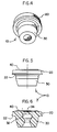
- numeral 10 shows one embodiment of the stopper of the present invention comprising: a head portion 20 and a leg portion 30.
- Head portion 20 comprises a flange 22 which is adapted to cover a corresponding planar, circular mouth portion of a medical vial, while leg portion 30 is adapted for insertion into the neck of the vial to tightly seal the content therein.
- Numeral 40 shows an abrasion-resistant film mounted on the centre part of the head portion 20 which serves as the piercing area for insertion and withdrawal of a spike or hypodermic needle.
- numeral 10' shows another embodiment of the stopper of the present invention comprising: a head portion 20' and a leg portion 30'.
- Head portion 20' comprises a flange 22' which is adapted to cover a corresponding planar, circular mouth portion of a medical vial, while leg portion 30' is adapted for insertion into the neck of the vial to tightly seal the content therein.
- Numeral 40' shows an abrasion-resistant film mounted on the top part of the head portion 20'.
- recess 32' extends toward the top surface of the head portion 20' forming a thin portion 34' in head portion 20' for facilitating piercing of the stopper by a spike.
- FIG. 7 illustrates a stopper 10 having an abrasion-resistant film 40 covering vial 1.
- Vial 1, containing an injectable fluid 5, is sealed by stopper (10 or 10') by inserting leg portion 30 of the stopper into the neck 7 of the vial 1.
- Flange portion 22 of head portion 20 tightly seals the mouth 8 of vial 1.
- a thin metal foil 9 is crimped over head portion 20 and flange portion 22 of stopper (10 or 10') to tightly seal and securely hold the stopper in vial 1.
- the elastomeric material of the stopper body must be a fluid-impervious, resilient and inert material without leachable additives therein in order to prevent any alteration of the product contained in the vial. It may be of a single component or a blend of components. Examples of materials include synthetic or natural rubber, such as butyl rubber, isoprene rubber, butadiene rubber, silicone rubber, halogenated rubber, ethylene propylene therpolymer and the like.
- a synthetic elastomeric rubber examples include the CH2CF2-C3F6(C3F5H) and the C2F4-C2F3OCF3 series of elastomers made by duPont under the trade names of VITON® and CARLEZ®; the fluoro-silicone rubbers, such as those made by Dow Corning under the name of SILASTIC®; and polyisobutylenes, such as VISTANEX MML-100 and MML-140; and halogenated butyl rubber, such as CHLOROBUTYL 1066, made by Exxon Chemical Company.
- elastomers may be made into the desired stopper configuration by known methods. Such methods conventionally include the use of a curing agent, a stabilizer and a filler and comprise a primary and secondary curing step at elevated temperatures.
- the abrasion-resistant coating for covering the top portion of the stopper, but at least the centre, pierceable portion thereof, may be: a polyvinyl, such as polystyrene, polyvinyl acetate (PVA), polyvinyl chloride (PVC), polyvinylidene chloride (PVDC), a copolymer of PVC and PVDC, polyvinyl fluoride, polyvinylidene fluoride, polychlorotrifluoroethylene and polytetrafluoroethylene ; a polyolefine, such as polypropylene and polymethylpentene; an ether, such a polymethylene oxide, polyphenylene oxide and polyphenylene sulphone; an ester, such as polyethylene terephthalate (PET), polycarbonate and copolyesters; an ester, such as polycaprolactam (Nylon 6), polyhexamethylene adipamide (Nylon 66) and polyundecanoamide (Nylon 11).
- the abrasion-resistant coating covering at least the centre, pierceable portion of the top surface of the stopper is preferably polytetrafluoroethylene sold under the trade name TEFLON by duPont.
- the coating thickness will be in the range of about 0.002 to 1.0 mm, and preferably about 0.02 to 0.5 mm.
- the coating may be applied or bonded to the stopper body in any suitable manner known in the art, such as, but not limited to, by the use of adhesives, solvents, spray applications, radio waves, infrared, microwaves, ultrasonics and heat or a combination thereof.
- the preferred stopper of the present invention comprising an elastomeric material and a TEFLON coating on the top centre portion thereof was tested against another stopper of the same elastomeric material but without the TEFLON coating thereon.
Landscapes
- Engineering & Computer Science (AREA)
- Mechanical Engineering (AREA)
- Closures For Containers (AREA)
- Medical Preparation Storing Or Oral Administration Devices (AREA)
- Polishing Bodies And Polishing Tools (AREA)
- Drilling Tools (AREA)
- Acyclic And Carbocyclic Compounds In Medicinal Compositions (AREA)
- Wrappers (AREA)
- Arc Welding In General (AREA)
- Control And Other Processes For Unpacking Of Materials (AREA)
- Passenger Equipment (AREA)
- Radiation-Therapy Devices (AREA)
- Physical Or Chemical Processes And Apparatus (AREA)
- Heating, Cooling, Or Curing Plastics Or The Like In General (AREA)
- Polysaccharides And Polysaccharide Derivatives (AREA)
- Transition And Organic Metals Composition Catalysts For Addition Polymerization (AREA)
- Solid-Sorbent Or Filter-Aiding Compositions (AREA)
- Infusion, Injection, And Reservoir Apparatuses (AREA)
- Media Introduction/Drainage Providing Device (AREA)
- Glass Compositions (AREA)
- Tires In General (AREA)
- Materials For Medical Uses (AREA)
Abstract
Description
- This invention relates to a stopper for a container and, more particularly, to an improved stopper for a container of parenteral solutions which is suitable for infusion spike penetration without producing unacceptable amounts of particulate matter.
- Stopper systems for vials, bottles and the like are made of materials that are resistant to chemicals and pharmaceuticals such as corrosive materials, reagents, parenteral solutions and solid formulations reconstitutable with a solvent prior to use. The most commonly used stopper system for such products has been glass or plastic bottles and vials equipped with rubber stoppers made of elastomeric materials. The system appears to provide for good hermetical seal, safe storage and easy access to the content through the elastomeric stopper via the use of an infusion spike when withdrawal of the content is desired. The elastomeric stopper used comprises an elastomeric base, such as natural or synthetic rubber and an inert coating covering at least some portions of the stopper. The coating used heretofore includes chlorobutyl rubber, polymeric fluorocarbon resins such as polytetrafluoroethylene (TEFLON) and various thermoplastic films. The coating is intended to insulate the elastomeric stopper base from the content of the container in order to prevent contact and possible chemical reactions therebetween.
- One of the major concerns in all products, and especially pharmaceutical parenteral products, is the generation of particulate foreign matter which may contaminate such products. In order to eliminate macroscopic and microscopic particulates, elaborate measures have been taken to remove them, such as filtration of the product and special washing and drying of the stopper system components. These steps help assure that the products meet the requirements and guidelines of the pharmaceutical industry, such as compendia guidelines, when the products reach the point of use. However, at the point of use, such as in the case of a parenteral product, new particulate matter is frequently generated by the practitioner when the stopper is penetrated by a needle or spike of an infusion set or an infusion spike. During such penetration a combination of elastic and plastic deformation of the stopper target area increases the stopper contact surface with the infusion spike as it is pressed into the stopper. Typically, untreated elastomeric stoppers offer a high degree of resistance against the exterior surface of the spike as the spike is being pushed into the penetration area. Most frequently, when stopper fragments are generated, they are the result of the elastomeric portion of the stopper being abraded off the upper surface of the stopper as it conforms to the shape of the penetrating spike. The fragments are then transported into the interior of the vial as the spike rolls and drags the fragments during penetration.
- In addition to the problem of particulate matter produced and carried into the vial during the spiking procedure, there are two other, although less frequently occurring, anomalies: stopper push-through into the vial and spike blow-out caused by residual elastic tension of the stopper against the spike which urges the spike outward.
- The most common solution to these problems has been the application of silicone lubricant to the stopper and/or the spike to reduce the frictional drag between the stopper and the spike. While silicone does reduce particle generation from the spiking procedure, it also increases the risk of product contamination from its own composition.
- Another approach proposed in the prior art to reduce the tendency of the stopper to generate particulate matter during manufacturing and storage is to coat the elastomeric core of the stopper with a thermoplastic film on the fluid-contacting side thereof. We have found, however, that the use of such construction is less than satisfactory to solve the problem.
- The present invention addresses the need to eliminate or at least greatly reduce the particle generation from surface erosion of the stopper during spike penetration. In addition, the invention reduces the risk of the push-through and blow-out tendency by minimizing frictional drag and residual elastic tension during spike penetration. These advantages are achieved without the use of a lubricant, such as silicone oil, which could contaminate the product contained in the vial or bottle.
- We have found surprisingly that if a non-reactive, inert, coating which is highly resistant to abrasion is applied to the upper surface of an elastomeric stopper where spike penetration will take place, particle generation during spiking is all but eliminated and the tendency of push-through as well as blow-out of the spike is greatly reduced.
- Accordingly this invention provides an abrasion-resistant stopper for a medical vial for containing a fluid therein comprising:
a stopper body of an elastomeric material having a head portion and a fluid contactable leg portion,
said leg portion being adapted to be inserted into said medical vial for hermetically sealing said fluid therein, and
said head portion comprising a top surface to receive a coating thereon, said top surface being coated with an abrasion-resistant coating to prevent generation of particles upon piercing of the stopper by a spike or a hypodermic needle. - Preferably the coating covers at least the centre, pierceable portion of the top surface for spike or needle penetration of the stopper when withdrawal of fluid is desired.
- In use, the coating on the top surface of the stopper conforms to the deformation of the stopper caused by the spike penetration procedure. It appears that, upon piercing, the spike is not in contact with the elastomeric stopper body but only with the abrasion-resistant coating thereby circumventing abrasion and eliminating the formation of elastomeric particulate materials.
- The invention will now be more fully described with reference to the following drawings in which
- FIG. 1 is a perspective view of one embodiment of the stopper of the present invention;
- FIG. 2 is a plan view of the stopper shown in FIG. 1;
- FIG. 3 is a cross-sectional view of the stopper shown in FIG. 2 taken along the line a - a;
- FIG. 4 is a perspective view of another embodiment of the stopper of the present invention;
- FIG. 5 is a plan view of the stopper shown in FIG.4;
- FIG. 6 is a cross-sectional view of the stopper shown in FIG. 2 taken along the line b - b; and
- FIG. 7 is a cross-section of a vial containing an injectable liquid closed with the stopper of the present invention.
- Referring to FIGS. 1, 2 and 3,
numeral 10 shows one embodiment of the stopper of the present invention comprising: ahead portion 20 and aleg portion 30.Head portion 20 comprises aflange 22 which is adapted to cover a corresponding planar, circular mouth portion of a medical vial, whileleg portion 30 is adapted for insertion into the neck of the vial to tightly seal the content therein. Numeral 40 shows an abrasion-resistant film mounted on the centre part of thehead portion 20 which serves as the piercing area for insertion and withdrawal of a spike or hypodermic needle. - Referring to FIGS. 4, 5 and 6, numeral 10' shows another embodiment of the stopper of the present invention comprising: a head portion 20' and a leg portion 30'. Head portion 20' comprises a flange 22' which is adapted to cover a corresponding planar, circular mouth portion of a medical vial, while leg portion 30' is adapted for insertion into the neck of the vial to tightly seal the content therein. Numeral 40' shows an abrasion-resistant film mounted on the top part of the head portion 20'. In this embodiment recess 32' extends toward the top surface of the head portion 20' forming a thin portion 34' in head portion 20' for facilitating piercing of the stopper by a spike.
- FIG. 7 illustrates a
stopper 10 having an abrasion-resistant film 40 covering vial 1. Vial 1, containing aninjectable fluid 5, is sealed by stopper (10 or 10') by insertingleg portion 30 of the stopper into theneck 7 of the vial 1.Flange portion 22 ofhead portion 20 tightly seals themouth 8 of vial 1. Athin metal foil 9 is crimped overhead portion 20 andflange portion 22 of stopper (10 or 10') to tightly seal and securely hold the stopper in vial 1. - The elastomeric material of the stopper body must be a fluid-impervious, resilient and inert material without leachable additives therein in order to prevent any alteration of the product contained in the vial. It may be of a single component or a blend of components. Examples of materials include synthetic or natural rubber, such as butyl rubber, isoprene rubber, butadiene rubber, silicone rubber, halogenated rubber, ethylene propylene therpolymer and the like. Specific examples of a synthetic elastomeric rubber include the CH₂CF₂-C₃F₆(C₃F₅H) and the C₂F₄-C₂F₃OCF₃ series of elastomers made by duPont under the trade names of VITON® and CARLEZ®; the fluoro-silicone rubbers, such as those made by Dow Corning under the name of SILASTIC®; and polyisobutylenes, such as VISTANEX MML-100 and MML-140; and halogenated butyl rubber, such as CHLOROBUTYL 1066, made by Exxon Chemical Company.
- These or other suitable elastomers may be made into the desired stopper configuration by known methods. Such methods conventionally include the use of a curing agent, a stabilizer and a filler and comprise a primary and secondary curing step at elevated temperatures.
- The abrasion-resistant coating for covering the top portion of the stopper, but at least the centre, pierceable portion thereof, may be: a polyvinyl, such as polystyrene, polyvinyl acetate (PVA), polyvinyl chloride (PVC), polyvinylidene chloride (PVDC), a copolymer of PVC and PVDC, polyvinyl fluoride, polyvinylidene fluoride, polychlorotrifluoroethylene and polytetrafluoroethylene ; a polyolefine, such as polypropylene and polymethylpentene; an ether, such a polymethylene oxide, polyphenylene oxide and polyphenylene sulphone; an ester, such as polyethylene terephthalate (PET), polycarbonate and copolyesters; an ester, such as polycaprolactam (Nylon 6), polyhexamethylene adipamide (Nylon 66) and polyundecanoamide (Nylon 11).
- The abrasion-resistant coating covering at least the centre, pierceable portion of the top surface of the stopper is preferably polytetrafluoroethylene sold under the trade name TEFLON by duPont.
- The coating thickness will be in the range of about 0.002 to 1.0 mm, and preferably about 0.02 to 0.5 mm. The coating may be applied or bonded to the stopper body in any suitable manner known in the art, such as, but not limited to, by the use of adhesives, solvents, spray applications, radio waves, infrared, microwaves, ultrasonics and heat or a combination thereof.
- The preferred stopper of the present invention comprising an elastomeric material and a TEFLON coating on the top centre portion thereof was tested against another stopper of the same elastomeric material but without the TEFLON coating thereon.
- The vials were capped with the stoppers. Each stopper was pierced with a spike and then the spike was removed. The vials were examined for the presence of elastomeric particles caused by the piercing. The result of the spiking is shown in Table 1.
TABLE 1 Stopper No. of Samples Mean Particle Count Present Invention 25 0.6 Elastomeric (Control) 25 15.4 - The present invention has been described in connection with the preferred embodiments shown in the drawings but is in no way limited thereto. It is to be noted that various changes and modifications are apparent to those skilled in the art.
Claims (15)
- An abrasion-resistant stopper for a medical vial for containing a fluid therein comprising:
a stopper body of an elastomeric material having a head portion and a fluid contactable leg portion,
said leg portion being adapted to be inserted into said medical vial for hermetically sealing said fluid therein, and
said head portion comprising a top surface to receive a coating thereon, said top surface being coated with an abrasion-resistant coating to prevent generation of particles upon piercing of the stopper by a spike or a hypodermic needle. - A stopper as claimed in claim 1 wherein said coating covers the centre, pierceable portion of said top surface.
- A stopper as claimed in either of the preceding claims wherein said coating is applied to said top surface by the use of an adhesive, solvent, spray application, radio waves, infrared, microwaves, ultrasonics, heat or a combination thereof.
- A stopper as claimed in any one of claims 1 to 3 wherein said coating is a polyvinyl.
- A stopper as claimed in claim 4 wherein the coating is selected from the group consisting of polystyrene, polyvinyl acetate, polyvinyl chloride, polyvinylidene chloride, a copolymer of polyvinyl chloride and polyvinylidene chloride, polyvinyl fluoride, polyvinylidene fluoride, polychlorotrifluoroethylene and polytetrafluoroethylene.
- A stopper as claimed in claim 5 wherein the coating is polytetrafluoroethylene
- A stopper as claimed in any one of claims 1 to 3 wherein said coating is a polyolefine.
- A stopper as claimed in claim 7 wherein the coating is selected from the group consisting of polypropylene and polymethylpentene.
- A stopper as claimed in any one of claims 1 to 3 wherein said coating is an ether.
- A stopper as claimed in claim 9 wherein the coating is selected from the group consisting of polymethylene oxide, polyphenylene oxide and polyphenylene sulphone.
- A stopper as claimed in any one of claims 1 to 3 wherein said coating is an ester.
- A stopper as claimed in claim 11 wherein the coating is selected from the group consisting of polyethylene terephthalate, polycarbonate and copolyesters.
- A stopper as claimed in claim 11 wherein the coating is selected from the group consisting of polycaprolactam, polyhexamethylene adipamide and polyundecanoamide.
- A stopper as claimed in any one of the preceding claims wherein the coating has a thickness of about 0.002 to 1.0 mm.
- A stopper as claimed in claim 14 wherein the coating has a thickness of about 0.02 to 0.5 mm.
Applications Claiming Priority (2)
| Application Number | Priority Date | Filing Date | Title |
|---|---|---|---|
| US86212092A | 1992-04-02 | 1992-04-02 | |
| US862120 | 1992-04-02 |
Publications (2)
| Publication Number | Publication Date |
|---|---|
| EP0564037A1 true EP0564037A1 (en) | 1993-10-06 |
| EP0564037B1 EP0564037B1 (en) | 1997-07-30 |
Family
ID=25337719
Family Applications (1)
| Application Number | Title | Priority Date | Filing Date |
|---|---|---|---|
| EP93200885A Expired - Lifetime EP0564037B1 (en) | 1992-04-02 | 1993-03-27 | Abrasion resistant stopper to prevent generation of particles by piercing |
Country Status (20)
| Country | Link |
|---|---|
| EP (1) | EP0564037B1 (en) |
| JP (1) | JPH0639017A (en) |
| KR (1) | KR930021174A (en) |
| AT (1) | ATE156088T1 (en) |
| AU (1) | AU666910B2 (en) |
| BR (1) | BR9301388A (en) |
| CA (1) | CA2091020C (en) |
| CZ (1) | CZ54393A3 (en) |
| DE (1) | DE69312545T2 (en) |
| DK (1) | DK0564037T3 (en) |
| ES (1) | ES2108205T3 (en) |
| FI (1) | FI931501L (en) |
| HU (1) | HUT67955A (en) |
| IL (1) | IL105247A (en) |
| MX (1) | MX9301044A (en) |
| MY (1) | MY131318A (en) |
| NO (1) | NO931288L (en) |
| NZ (1) | NZ247323A (en) |
| SK (1) | SK27493A3 (en) |
| TW (1) | TW227523B (en) |
Cited By (6)
| Publication number | Priority date | Publication date | Assignee | Title |
|---|---|---|---|---|
| WO2004018317A3 (en) * | 2002-08-16 | 2004-05-27 | Glaxosmithkline Biolog Sa | Closure system for a vial, vial, method of closing and filling a vial and stand for a vial |
| CN102283776A (en) * | 2011-07-07 | 2011-12-21 | 海南卫康制药(潜山)有限公司 | Puncture-free bottle cork and application method thereof |
| EP2546152A3 (en) * | 2002-09-03 | 2014-03-26 | Medical Instill Technologies, Inc. | Sealed containers and methods of making and filling same |
| EP2817237A2 (en) * | 2012-02-24 | 2014-12-31 | Krones AG | Pierceable plastic closure for closing containers |
| WO2020142592A1 (en) * | 2019-01-04 | 2020-07-09 | Instrumentation Laboratory Company | Container stopper for high pierce count applications |
| US12434889B2 (en) | 2022-12-09 | 2025-10-07 | Instrumentation Laboratory Company | Sealing systems |
Families Citing this family (6)
| Publication number | Priority date | Publication date | Assignee | Title |
|---|---|---|---|---|
| US6386392B1 (en) | 1999-11-02 | 2002-05-14 | The Procter & Gamble Company | Reservoirs for use with cleaning devices |
| EP1078880B1 (en) | 1999-08-05 | 2003-03-19 | The Procter & Gamble Company | Dispensing device comprising a reservoir and attachment means provided with protected piercing means |
| US6321941B1 (en) | 2000-04-20 | 2001-11-27 | The Procter & Gamble Company | Consumer safe fitment for connecting a reservoir to a dispensing appliance |
| JP4601127B2 (en) * | 2000-06-06 | 2010-12-22 | 住友ゴム工業株式会社 | Medical rubber stopper |
| US20090196798A1 (en) * | 2008-02-06 | 2009-08-06 | Robert Sassa | Barrier with Low Extractables and Resealing Properties |
| USD713931S1 (en) | 2013-01-09 | 2014-09-23 | Central Garden & Pet Company | Sprayer |
Citations (3)
| Publication number | Priority date | Publication date | Assignee | Title |
|---|---|---|---|---|
| US4499148A (en) * | 1983-01-10 | 1985-02-12 | Canton Bio-Medical Products, Inc. | Composite materials of silicone elastomers and polyolefin films, and method of making |
| EP0294127A2 (en) * | 1987-05-29 | 1988-12-07 | Daikyo Gomu Seiko Ltd. | Resin-laminated rubber stopper |
| DE8906346U1 (en) * | 1989-05-23 | 1989-09-14 | Pharma-Gummi Wimmer West Gmbh, 5180 Eschweiler | Closure for medicine bottles |
Family Cites Families (1)
| Publication number | Priority date | Publication date | Assignee | Title |
|---|---|---|---|---|
| US3628681A (en) * | 1969-10-06 | 1971-12-21 | Plastics Consulting And Mfg Co | Stopper |
-
1993
- 1993-02-04 AU AU32805/93A patent/AU666910B2/en not_active Ceased
- 1993-02-22 TW TW082101220A patent/TW227523B/zh active
- 1993-02-25 MX MX9301044A patent/MX9301044A/en unknown
- 1993-03-04 CA CA002091020A patent/CA2091020C/en not_active Expired - Lifetime
- 1993-03-27 ES ES93200885T patent/ES2108205T3/en not_active Expired - Lifetime
- 1993-03-27 AT AT93200885T patent/ATE156088T1/en not_active IP Right Cessation
- 1993-03-27 DE DE69312545T patent/DE69312545T2/en not_active Expired - Lifetime
- 1993-03-27 EP EP93200885A patent/EP0564037B1/en not_active Expired - Lifetime
- 1993-03-27 DK DK93200885.7T patent/DK0564037T3/en active
- 1993-03-29 JP JP5069697A patent/JPH0639017A/en active Pending
- 1993-03-31 CZ CZ93543A patent/CZ54393A3/en unknown
- 1993-03-31 KR KR1019930005347A patent/KR930021174A/en not_active Withdrawn
- 1993-03-31 BR BR9301388A patent/BR9301388A/en not_active Application Discontinuation
- 1993-04-01 IL IL105247A patent/IL105247A/en not_active IP Right Cessation
- 1993-04-02 HU HU9300971A patent/HUT67955A/en unknown
- 1993-04-02 MY MYPI93000586A patent/MY131318A/en unknown
- 1993-04-02 FI FI931501A patent/FI931501L/en not_active Application Discontinuation
- 1993-04-02 NZ NZ247323A patent/NZ247323A/en unknown
- 1993-04-02 NO NO93931288A patent/NO931288L/en unknown
- 1993-04-05 SK SK274-93A patent/SK27493A3/en unknown
Patent Citations (3)
| Publication number | Priority date | Publication date | Assignee | Title |
|---|---|---|---|---|
| US4499148A (en) * | 1983-01-10 | 1985-02-12 | Canton Bio-Medical Products, Inc. | Composite materials of silicone elastomers and polyolefin films, and method of making |
| EP0294127A2 (en) * | 1987-05-29 | 1988-12-07 | Daikyo Gomu Seiko Ltd. | Resin-laminated rubber stopper |
| DE8906346U1 (en) * | 1989-05-23 | 1989-09-14 | Pharma-Gummi Wimmer West Gmbh, 5180 Eschweiler | Closure for medicine bottles |
Cited By (15)
| Publication number | Priority date | Publication date | Assignee | Title |
|---|---|---|---|---|
| US8960242B2 (en) | 2000-02-11 | 2015-02-24 | Medinstill Development Llc | Sealed containers and methods of filling and resealing same |
| US9637251B2 (en) | 2000-02-11 | 2017-05-02 | Medinstill Development Llc | Sealed containers and methods of filling and resealing same |
| US9051064B2 (en) | 2000-02-11 | 2015-06-09 | Medinstill Development Llc | Resealable containers and methods of making, filling and resealing same |
| EP2006213A3 (en) * | 2002-08-16 | 2008-12-31 | GlaxoSmithKline Biologicals S.A. | Vial and closure system for a vial |
| US7946437B2 (en) | 2002-08-16 | 2011-05-24 | Aseptic Technologies S.A. | Closure system for a vial, vial, method of closing and filling a vial and stand for a vial |
| WO2004018317A3 (en) * | 2002-08-16 | 2004-05-27 | Glaxosmithkline Biolog Sa | Closure system for a vial, vial, method of closing and filling a vial and stand for a vial |
| RU2333141C2 (en) * | 2002-08-16 | 2008-09-10 | ГлаксоСмитКлайн Байолоджикалз с.а. | Flask closing device, flask, method filling flask and flask support |
| CN100347052C (en) * | 2002-08-16 | 2007-11-07 | 葛兰素史密丝克莱恩生物有限公司 | Closure system for a vial, vial, method of closing and filling a vial and stand for a vial |
| EP2546152A3 (en) * | 2002-09-03 | 2014-03-26 | Medical Instill Technologies, Inc. | Sealed containers and methods of making and filling same |
| CN102283776A (en) * | 2011-07-07 | 2011-12-21 | 海南卫康制药(潜山)有限公司 | Puncture-free bottle cork and application method thereof |
| EP2817237A2 (en) * | 2012-02-24 | 2014-12-31 | Krones AG | Pierceable plastic closure for closing containers |
| WO2020142592A1 (en) * | 2019-01-04 | 2020-07-09 | Instrumentation Laboratory Company | Container stopper for high pierce count applications |
| CN113474083A (en) * | 2019-01-04 | 2021-10-01 | 仪器实验室公司 | Container stopper for high puncture count applications |
| US11319122B2 (en) | 2019-01-04 | 2022-05-03 | Instrumentation Laboratory Company | Container stopper for high pierce count applications |
| US12434889B2 (en) | 2022-12-09 | 2025-10-07 | Instrumentation Laboratory Company | Sealing systems |
Also Published As
| Publication number | Publication date |
|---|---|
| IL105247A0 (en) | 1993-08-18 |
| FI931501A7 (en) | 1993-10-03 |
| BR9301388A (en) | 1993-10-13 |
| ES2108205T3 (en) | 1997-12-16 |
| EP0564037B1 (en) | 1997-07-30 |
| MX9301044A (en) | 1993-10-01 |
| FI931501A0 (en) | 1993-04-02 |
| DK0564037T3 (en) | 1997-09-29 |
| HUT67955A (en) | 1995-05-29 |
| MY131318A (en) | 2007-08-30 |
| HU9300971D0 (en) | 1993-06-28 |
| TW227523B (en) | 1994-08-01 |
| AU3280593A (en) | 1993-10-07 |
| SK27493A3 (en) | 1993-11-10 |
| NO931288L (en) | 1993-10-04 |
| CA2091020A1 (en) | 1993-10-03 |
| IL105247A (en) | 1997-04-15 |
| CA2091020C (en) | 2005-01-25 |
| NZ247323A (en) | 1996-03-26 |
| JPH0639017A (en) | 1994-02-15 |
| KR930021174A (en) | 1993-11-22 |
| CZ54393A3 (en) | 1995-11-15 |
| DE69312545T2 (en) | 1998-02-19 |
| ATE156088T1 (en) | 1997-08-15 |
| DE69312545D1 (en) | 1997-09-04 |
| FI931501L (en) | 1993-10-03 |
| NO931288D0 (en) | 1993-04-02 |
| AU666910B2 (en) | 1996-02-29 |
Similar Documents
| Publication | Publication Date | Title |
|---|---|---|
| US5219083A (en) | Stopper for reduction of particulate matter | |
| US5064083A (en) | Closure device | |
| EP0573102B1 (en) | Double-seal elastomeric stopper | |
| CA2255507C (en) | Medicament container closure with recessed integral spike access means | |
| EP0960616B1 (en) | Multiple use universal stopper | |
| AU666910B2 (en) | Improved stopper for reduction of particulate matter | |
| US6681475B2 (en) | Method of sealing a medical container with a plastic closure | |
| US6024235A (en) | Container seal with a sealing body which can be punctured | |
| EP0814027B1 (en) | Laminated rubber stopper | |
| US7615271B2 (en) | Method of fusing a component to a medical storage or transfer device and container assembly | |
| US6613283B2 (en) | Vial pack cover, vial pack kit, and method for forming the vial pack cover | |
| EP0172613A2 (en) | Resin-laminated rubber plug | |
| CA2261428A1 (en) | Medicament container stopper with integral spike access means | |
| US3313439A (en) | Closures for containers | |
| JP3867215B2 (en) | Sealing plug for pharmaceutical container and pharmaceutical container assembly | |
| US6682518B1 (en) | Injectable micro-glass vial | |
| CN1223329C (en) | Improvements to Medical Containers | |
| CA1052732A (en) | Closable sterile container | |
| US20030201239A1 (en) | Radially compressed self-sealing septum | |
| US6461345B1 (en) | Cannula operated pinch valve | |
| HK1028872A (en) | Improvements related to medical containers |
Legal Events
| Date | Code | Title | Description |
|---|---|---|---|
| PUAI | Public reference made under article 153(3) epc to a published international application that has entered the european phase |
Free format text: ORIGINAL CODE: 0009012 |
|
| AK | Designated contracting states |
Kind code of ref document: A1 Designated state(s): AT BE CH DE DK ES FR GB GR IE IT LI LU MC NL PT SE |
|
| 17P | Request for examination filed |
Effective date: 19940316 |
|
| 17Q | First examination report despatched |
Effective date: 19950413 |
|
| RAP1 | Party data changed (applicant data changed or rights of an application transferred) |
Owner name: NYCOMED IMAGING AS |
|
| GRAG | Despatch of communication of intention to grant |
Free format text: ORIGINAL CODE: EPIDOS AGRA |
|
| GRAH | Despatch of communication of intention to grant a patent |
Free format text: ORIGINAL CODE: EPIDOS IGRA |
|
| GRAH | Despatch of communication of intention to grant a patent |
Free format text: ORIGINAL CODE: EPIDOS IGRA |
|
| GRAA | (expected) grant |
Free format text: ORIGINAL CODE: 0009210 |
|
| AK | Designated contracting states |
Kind code of ref document: B1 Designated state(s): AT BE CH DE DK ES FR GB GR IE IT LI LU MC NL PT SE |
|
| PG25 | Lapsed in a contracting state [announced via postgrant information from national office to epo] |
Ref country code: NL Free format text: LAPSE BECAUSE OF FAILURE TO SUBMIT A TRANSLATION OF THE DESCRIPTION OR TO PAY THE FEE WITHIN THE PRESCRIBED TIME-LIMIT Effective date: 19970730 Ref country code: LI Effective date: 19970730 Ref country code: GR Free format text: LAPSE BECAUSE OF FAILURE TO SUBMIT A TRANSLATION OF THE DESCRIPTION OR TO PAY THE FEE WITHIN THE PRESCRIBED TIME-LIMIT Effective date: 19970730 Ref country code: CH Effective date: 19970730 Ref country code: BE Effective date: 19970730 Ref country code: AT Effective date: 19970730 |
|
| REF | Corresponds to: |
Ref document number: 156088 Country of ref document: AT Date of ref document: 19970815 Kind code of ref document: T |
|
| REG | Reference to a national code |
Ref country code: CH Ref legal event code: EP |
|
| REF | Corresponds to: |
Ref document number: 69312545 Country of ref document: DE Date of ref document: 19970904 |
|
| REG | Reference to a national code |
Ref country code: DK Ref legal event code: T3 |
|
| ITF | It: translation for a ep patent filed | ||
| PG25 | Lapsed in a contracting state [announced via postgrant information from national office to epo] |
Ref country code: SE Effective date: 19971030 |
|
| PG25 | Lapsed in a contracting state [announced via postgrant information from national office to epo] |
Ref country code: PT Effective date: 19971105 |
|
| ET | Fr: translation filed | ||
| REG | Reference to a national code |
Ref country code: ES Ref legal event code: FG2A Ref document number: 2108205 Country of ref document: ES Kind code of ref document: T3 |
|
| NLV1 | Nl: lapsed or annulled due to failure to fulfill the requirements of art. 29p and 29m of the patents act | ||
| REG | Reference to a national code |
Ref country code: CH Ref legal event code: PL |
|
| PG25 | Lapsed in a contracting state [announced via postgrant information from national office to epo] |
Ref country code: LU Free format text: LAPSE BECAUSE OF NON-PAYMENT OF DUE FEES Effective date: 19980327 |
|
| PG25 | Lapsed in a contracting state [announced via postgrant information from national office to epo] |
Ref country code: DK Free format text: LAPSE BECAUSE OF NON-PAYMENT OF DUE FEES Effective date: 19980331 |
|
| PLBE | No opposition filed within time limit |
Free format text: ORIGINAL CODE: 0009261 |
|
| STAA | Information on the status of an ep patent application or granted ep patent |
Free format text: STATUS: NO OPPOSITION FILED WITHIN TIME LIMIT |
|
| 26N | No opposition filed | ||
| PG25 | Lapsed in a contracting state [announced via postgrant information from national office to epo] |
Ref country code: MC Free format text: LAPSE BECAUSE OF NON-PAYMENT OF DUE FEES Effective date: 19980930 |
|
| REG | Reference to a national code |
Ref country code: DK Ref legal event code: EBP |
|
| REG | Reference to a national code |
Ref country code: GB Ref legal event code: IF02 |
|
| PGFP | Annual fee paid to national office [announced via postgrant information from national office to epo] |
Ref country code: IE Payment date: 20120326 Year of fee payment: 20 Ref country code: FR Payment date: 20120406 Year of fee payment: 20 |
|
| PGFP | Annual fee paid to national office [announced via postgrant information from national office to epo] |
Ref country code: GB Payment date: 20120326 Year of fee payment: 20 Ref country code: IT Payment date: 20120327 Year of fee payment: 20 |
|
| PGFP | Annual fee paid to national office [announced via postgrant information from national office to epo] |
Ref country code: DE Payment date: 20120328 Year of fee payment: 20 |
|
| REG | Reference to a national code |
Ref country code: DE Ref legal event code: R082 Ref document number: 69312545 Country of ref document: DE Representative=s name: J D REYNOLDS & CO., GB |
|
| REG | Reference to a national code |
Ref country code: DE Ref legal event code: R071 Ref document number: 69312545 Country of ref document: DE |
|
| REG | Reference to a national code |
Ref country code: GB Ref legal event code: PE20 Expiry date: 20130326 |
|
| PG25 | Lapsed in a contracting state [announced via postgrant information from national office to epo] |
Ref country code: GB Free format text: LAPSE BECAUSE OF EXPIRATION OF PROTECTION Effective date: 20130326 Ref country code: DE Free format text: LAPSE BECAUSE OF EXPIRATION OF PROTECTION Effective date: 20130328 |
|
| PGFP | Annual fee paid to national office [announced via postgrant information from national office to epo] |
Ref country code: ES Payment date: 20120326 Year of fee payment: 20 |
|
| REG | Reference to a national code |
Ref country code: ES Ref legal event code: FD2A Effective date: 20130705 |
|
| PG25 | Lapsed in a contracting state [announced via postgrant information from national office to epo] |
Ref country code: ES Free format text: LAPSE BECAUSE OF EXPIRATION OF PROTECTION Effective date: 20130328 |
|
| PG25 | Lapsed in a contracting state [announced via postgrant information from national office to epo] |
Ref country code: IE Free format text: LAPSE BECAUSE OF EXPIRATION OF PROTECTION Effective date: 20130327 |