EP0563356B1 - Dispositif et methode de controle non destructif et continu d'une variation de l'epaisseur de profiles - Google Patents
Dispositif et methode de controle non destructif et continu d'une variation de l'epaisseur de profiles Download PDFInfo
- Publication number
- EP0563356B1 EP0563356B1 EP92921797A EP92921797A EP0563356B1 EP 0563356 B1 EP0563356 B1 EP 0563356B1 EP 92921797 A EP92921797 A EP 92921797A EP 92921797 A EP92921797 A EP 92921797A EP 0563356 B1 EP0563356 B1 EP 0563356B1
- Authority
- EP
- European Patent Office
- Prior art keywords
- section
- radiation
- measuring
- thickness
- profile
- Prior art date
- Legal status (The legal status is an assumption and is not a legal conclusion. Google has not performed a legal analysis and makes no representation as to the accuracy of the status listed.)
- Expired - Lifetime
Links
- 238000012544 monitoring process Methods 0.000 title claims abstract description 5
- 238000000034 method Methods 0.000 title claims description 20
- 230000005855 radiation Effects 0.000 claims abstract description 42
- 230000010512 thermal transition Effects 0.000 claims abstract 3
- 238000001514 detection method Methods 0.000 claims description 14
- 238000010438 heat treatment Methods 0.000 claims description 13
- 238000012545 processing Methods 0.000 claims description 5
- 239000012530 fluid Substances 0.000 claims description 3
- 239000007788 liquid Substances 0.000 claims description 3
- 230000001960 triggered effect Effects 0.000 claims description 3
- 230000001360 synchronised effect Effects 0.000 claims description 2
- 238000005259 measurement Methods 0.000 description 20
- 230000001066 destructive effect Effects 0.000 description 8
- 239000000463 material Substances 0.000 description 8
- 238000001816 cooling Methods 0.000 description 5
- 238000001125 extrusion Methods 0.000 description 4
- 238000004519 manufacturing process Methods 0.000 description 4
- LYCAIKOWRPUZTN-UHFFFAOYSA-N Ethylene glycol Chemical compound OCCO LYCAIKOWRPUZTN-UHFFFAOYSA-N 0.000 description 3
- 239000002033 PVDF binder Substances 0.000 description 3
- 229920002981 polyvinylidene fluoride Polymers 0.000 description 3
- 239000012815 thermoplastic material Substances 0.000 description 3
- 230000001052 transient effect Effects 0.000 description 3
- IJGRMHOSHXDMSA-UHFFFAOYSA-N Atomic nitrogen Chemical compound N#N IJGRMHOSHXDMSA-UHFFFAOYSA-N 0.000 description 2
- 239000004952 Polyamide Substances 0.000 description 2
- 239000004698 Polyethylene Substances 0.000 description 2
- 239000004743 Polypropylene Substances 0.000 description 2
- 238000012550 audit Methods 0.000 description 2
- WERYXYBDKMZEQL-UHFFFAOYSA-N butane-1,4-diol Chemical compound OCCCCO WERYXYBDKMZEQL-UHFFFAOYSA-N 0.000 description 2
- 229920002647 polyamide Polymers 0.000 description 2
- -1 polyethylene Polymers 0.000 description 2
- 229920000573 polyethylene Polymers 0.000 description 2
- 229920001155 polypropylene Polymers 0.000 description 2
- 239000004800 polyvinyl chloride Substances 0.000 description 2
- 229920000915 polyvinyl chloride Polymers 0.000 description 2
- 238000007493 shaping process Methods 0.000 description 2
- 238000012800 visualization Methods 0.000 description 2
- 229920000049 Carbon (fiber) Polymers 0.000 description 1
- 229920000271 Kevlar® Polymers 0.000 description 1
- 239000012790 adhesive layer Substances 0.000 description 1
- 239000004760 aramid Substances 0.000 description 1
- 229920003235 aromatic polyamide Polymers 0.000 description 1
- 230000015572 biosynthetic process Effects 0.000 description 1
- 239000004917 carbon fiber Substances 0.000 description 1
- 150000002009 diols Chemical class 0.000 description 1
- 230000002349 favourable effect Effects 0.000 description 1
- 239000000835 fiber Substances 0.000 description 1
- 239000003365 glass fiber Substances 0.000 description 1
- 238000000265 homogenisation Methods 0.000 description 1
- 229910052500 inorganic mineral Inorganic materials 0.000 description 1
- 230000005865 ionizing radiation Effects 0.000 description 1
- 239000004761 kevlar Substances 0.000 description 1
- 239000010410 layer Substances 0.000 description 1
- 238000000691 measurement method Methods 0.000 description 1
- 239000011707 mineral Substances 0.000 description 1
- 238000012986 modification Methods 0.000 description 1
- 230000004048 modification Effects 0.000 description 1
- 229910052757 nitrogen Inorganic materials 0.000 description 1
- 238000003303 reheating Methods 0.000 description 1
- 238000007650 screen-printing Methods 0.000 description 1
- 230000035945 sensitivity Effects 0.000 description 1
- 239000007787 solid Substances 0.000 description 1
- 230000003595 spectral effect Effects 0.000 description 1
- 238000002076 thermal analysis method Methods 0.000 description 1
- 229920001169 thermoplastic Polymers 0.000 description 1
- 239000004416 thermosoftening plastic Substances 0.000 description 1
- 238000002604 ultrasonography Methods 0.000 description 1
- XLYOFNOQVPJJNP-UHFFFAOYSA-N water Substances O XLYOFNOQVPJJNP-UHFFFAOYSA-N 0.000 description 1
Images
Classifications
-
- G—PHYSICS
- G01—MEASURING; TESTING
- G01B—MEASURING LENGTH, THICKNESS OR SIMILAR LINEAR DIMENSIONS; MEASURING ANGLES; MEASURING AREAS; MEASURING IRREGULARITIES OF SURFACES OR CONTOURS
- G01B11/00—Measuring arrangements characterised by the use of optical techniques
- G01B11/02—Measuring arrangements characterised by the use of optical techniques for measuring length, width or thickness
- G01B11/06—Measuring arrangements characterised by the use of optical techniques for measuring length, width or thickness for measuring thickness ; e.g. of sheet material
Definitions
- the present invention relates to a device and to a method for non-destructive and continuous measurement and / or control of the thickness of a profile.
- Document WO 81/03704 describes a method for examining the surface of a solid according to which a pulsed infrared source is punctually sent towards the object and the resulting radiation is analyzed.
- the document JP 2 309 205 discloses a way of measuring the thickness of an adhesive layer by measuring the heat stored by this layer.
- the present invention provides a method and a device for non-destructive and continuous measurement and / or control of the thickness of a profile overcoming the drawbacks of the methods of the prior art.
- the method and the device according to the invention easily apply to the case of corrugated sections whatever the shape and amplitude of the corrugations.
- the method of the invention is based on the measurement of the radiation emitted by the profile during a heating phase or a cooling phase.
- a material of substantially homogeneous density cools, or heats up, the more quickly the less its thickness.
- the radiation emitted by the profile during a thermal transient regime that is to say during its heating or at during its cooling, it is possible to observe or measure continuously thicknesses or variations in thickness.
- a material of substantially homogeneous density emits radiation, in particular infrared, whose power is proportional to the fourth power of its surface temperature.
- radiation in particular infrared
- the evolution of the surface temperature depends on the thickness of the profile.
- each thickness variation corresponds to different surface temperatures, therefore radiation emissions, in particular infrared radiation of different powers. This phenomenon is more marked for materials with low thermal conductivity, and for which cooling or heating is generally faster than the homogenization of the temperature within the material.
- the present invention makes it possible in particular, but not exclusively, to carry out a continuous, non-destructive control, by infrared camera, of the thickness of thermoplastic corrugated tubes constituting for example the core of reinforced corrugated tubes.
- the device for non-destructive and continuous measurement and / or control of the thickness of a profile, according to the present invention uses this physical phenomenon.
- the means for detecting and measuring the radiation emitted comprises an infrared camera connected to a display screen and / or to a computer system comprising image processing software.
- the computer system will preferably include means for storing the images. provided by the infrared camera and / or results provided by the image processing software.
- the device will comprise at least one means allowing the profile to travel, for example tracks, and at least one means allowing the synchronization of this travel to the scanning movement of the detection and measurement means. of the radiation emitted, so that the entire surface of the profile is scanned by said detection and measurement means.
- the device of the present invention can be used for non-destructive and continuous measurement and / or control of the thickness of a profile during its manufacture.
- the profile heating means is constituted by the shaping device of said profile.
- This shaping device can be for example an extruder, a pultruder machine die or any other device well known to those skilled in the art.
- the device of the present invention can be used for non-destructive and continuous measurement and / or control of the thickness of a profile before its use, for example at the time of its manufacture, but also after its manufacture or in a remote site. from its place of manufacture.
- the means of heating or reheating said profile is usually chosen from the group formed by electrical resistances, gaseous fluids or hot liquids and sources of heat by radiation (for example ramps of infrared lamps).
- the heating can for example be obtained by circulation of a hot fluid, such as for example air, water, a mineral or organic oil, around said profile or in the case of a profile having the form d 'a tube, inside of it.
- the profile is most often heated so that its temperature is at least 50 ° C above ambient temperature in the area located at the level of the radiation detection and measurement means.
- the maximum heating temperature depends on the material or materials constituting said profile; it is most often at most equal to the profile formation temperature, for example the extrusion temperature of the thermoplastic material used which is most often about 160 to about 280 ° C.
- the position of the radiation detection and measurement means relative to that of the heating means depends both on the material of which the profile is made, on the temperature at which it is heated and on its average thickness.
- This detection and measurement means is preferably positioned at a point where the temperature of said profile is from about 50 ° C to about 140 ° C.
- the distance between this means and the profile itself is not critical and can be easily chosen by a person skilled in the art according to the characteristics of this detection and measurement means, and in particular according to its detection sensitivity.
- an alarm system may for example be controlled by the computer system, the image processing software of which can, after calibration, convert the measured temperatures into thicknesses. It is thus possible to set one or more thresholds or alarm levels. We could for example consider setting an alarm threshold for a thickness greater than a previously chosen value and an alarm threshold for a thickness less than a previously chosen value, or choose only one alarm threshold, for example for a thickness less than a previously chosen value.
- the means allowing the detection and measurement means to scan the entire surface of the profile can include a guide system such as for example a rail on which said detection and measurement means can be fixed so as to be mobile.
- the present invention also relates to a method of non-destructive and continuous measurement and / or control of the thickness of a profile, characterized in that it comprises in combination: the creation of a continuous variation of the temperature of said profile up to a temperature sufficient for said profile to emit radiation, the detection and measurement, over the entire surface of said profile, of the radiation emitted by said profile, the scanning of the entire surface of the profile by the detection and measurement means radiation and recording of the radiation emitted by the profile, its variation and / or its treatment using a computer system comprising image processing software.
- said profile is heated to a temperature such that it emits infrared radiation having a wavelength substantially between 2 and 25 micrometers and preferably between 2 and 5 micrometers.
- the method of the invention comprises scrolling the profile and recording the radiation emitted by synchronized scanning of the entire surface of the profile by the radiation detector.
- thermoplastic materials such as those made of polyethylene (PE), polypropylene (PP), polyamide (PA), polyvinyl chloride. (PVC), polyvinylidene fluoride (PVDF) and polyterephthalate diols such as ethylene glycol or 1,4-butanediol.
- thermoplastic materials may or may not be reinforced with fibers such as for example glass fibers, carbon fibers, or aromatic polyamides such as for example Kevlar (registered trademark).
- fibers such as for example glass fibers, carbon fibers, or aromatic polyamides such as for example Kevlar (registered trademark).
- Kevlar registered trademark
- the present method can be applied to the control and measurement of the thickness of flat or tubular profiles having a substantially circular, oval, elliptical, rectangular section or any other shape defined by a closed curve. It is particularly well suited for checking or measuring the thickness of tubes or corrugated sheets.
- the undulations can have any shape and a very variable amplitude. These undulations are for example undulations of sinusoidal, square or rectangular section.
- the profiles usually have an average thickness of about 0.1 millimeter to about 20 millimeters and most often about 0.2 millimeter to about 10 millimeters.
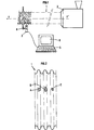
- FIG. 1 the device of the present invention is illustrated diagrammatically in FIG. 1 while FIG. 2 is a simplified visualization of a corrugated tube.
- the device according to the invention shown diagrammatically in FIG. 1, comprises an extrusion device 2 allowing the continuous extrusion of a tube 1, for example of substantially circular section and having undulations of sinusoidal section.
- the heating means 2e is in this case the extrusion apparatus itself.
- the tube moves along its longitudinal axis YY ', for example at substantially constant speed, and its surface is scanned by an infrared camera 3 positioned on a mobile carriage moving simultaneously on a rail 4 perpendicular to the axis YY' of the tube.
- the infrared camera is connected to a computer system 5 comprising a display screen 6.
- FIG. 2 is a visualization of a thickness control of a PVDF tube of average thickness equal to 1 millimeter.
- the device used to carry out this control is that shown diagrammatically in FIG. 1.
- the infrared camera used can be a camera known per se, for example a camera of the registered trademark THERMOVISION sold by the French company AGEMA, this camera is cooled to liquid nitrogen, and has a spectral band of 2 to 5 micrometers.
- the associated computer system can be a system marketed by the company AGEMA, referenced TIC-8000, comprising an IBM PC-AT computer and a program such as CATS-E developed by the company AGEMA for thermal analysis purposes.
- the screen printing reproduced in FIG. 2 is carried out using an inkjet printer known per se.
- the invention therefore consists in scanning the entire surface of the profile to be examined using an infrared camera 3, the profile then being in thermal transient, that is to say either during the heating period, or in cooling period, anyway emitting radiation capable of being detected by said camera.
- the computer system associated with the infrared camera 3 comprises in particular a means of recording the radiation emitted, a means of storing the images supplied by the camera, a means of processing said images, a means of storing the results supplied by the means image processing.
- each variation in thickness results in the appearance of a spot on the image of the profile viewed on the screen, a spot corresponding to a color variation or to a variation grayscale for black and white screens.
- FIG. 2 shows a simplified screen display according to which one can see three spots A, B, C corresponding respectively to three faults.
Landscapes
- Physics & Mathematics (AREA)
- General Physics & Mathematics (AREA)
- Investigating Or Analyzing Materials Using Thermal Means (AREA)
- Length Measuring Devices By Optical Means (AREA)
- Radiation Pyrometers (AREA)
- Length-Measuring Devices Using Wave Or Particle Radiation (AREA)
- Analysing Materials By The Use Of Radiation (AREA)
- Length Measuring Devices With Unspecified Measuring Means (AREA)
Applications Claiming Priority (3)
| Application Number | Priority Date | Filing Date | Title |
|---|---|---|---|
| FR9112989A FR2682757A1 (fr) | 1991-10-21 | 1991-10-21 | Dispositif et methode de controle non destructif et continu de l'epaisseur de profiles. |
| FR9112989 | 1991-10-21 | ||
| PCT/FR1992/000922 WO1993008446A1 (fr) | 1991-10-21 | 1992-09-30 | Dispositif et methode de controle non destructif et continu d'une variation de l'epaisseur de profiles |
Publications (2)
| Publication Number | Publication Date |
|---|---|
| EP0563356A1 EP0563356A1 (en) | 1993-10-06 |
| EP0563356B1 true EP0563356B1 (fr) | 1996-07-17 |
Family
ID=9418159
Family Applications (1)
| Application Number | Title | Priority Date | Filing Date |
|---|---|---|---|
| EP92921797A Expired - Lifetime EP0563356B1 (fr) | 1991-10-21 | 1992-09-30 | Dispositif et methode de controle non destructif et continu d'une variation de l'epaisseur de profiles |
Country Status (7)
| Country | Link |
|---|---|
| US (1) | US5399016A (OSRAM) |
| EP (1) | EP0563356B1 (OSRAM) |
| JP (1) | JPH06503650A (OSRAM) |
| DE (1) | DE69212299T2 (OSRAM) |
| ES (1) | ES2092132T3 (OSRAM) |
| FR (1) | FR2682757A1 (OSRAM) |
| WO (1) | WO1993008446A1 (OSRAM) |
Families Citing this family (21)
| Publication number | Priority date | Publication date | Assignee | Title |
|---|---|---|---|---|
| US5376793A (en) * | 1993-09-15 | 1994-12-27 | Stress Photonics, Inc. | Forced-diffusion thermal imaging apparatus and method |
| ATE188044T1 (de) * | 1994-12-23 | 2000-01-15 | Findlay Ind Deutschland Gmbh | Verfahren und vorrichtung zum bestimmen der auf einer flächeneinheit vorliegenden menge eines klebstoffes sowie verfahren und vorrichtung zum steuern der auf eine flächeneinheit aufzutragenden menge eines klebstoffes |
| US6224699B1 (en) | 1998-11-12 | 2001-05-01 | Kimberly-Clark Worldwide, Inc. | Infrared imaging to detect components on personal care articles |
| US6354984B1 (en) | 1999-04-02 | 2002-03-12 | Kimberly-Clark Worldwide, Inc. | Indirect registration of elements of web-derived product |
| US6352497B1 (en) | 1999-04-02 | 2002-03-05 | Kimberly-Clark Worldwide, Inc. | Detectable marks in trim material |
| US6394646B1 (en) * | 1999-04-16 | 2002-05-28 | General Electric Company | Method and apparatus for quantitative nondestructive evaluation of metal airfoils using high resolution transient thermography |
| US6367969B1 (en) * | 1999-07-21 | 2002-04-09 | General Electric Company | Synthetic reference thermal imaging method |
| US6927857B2 (en) * | 2002-03-09 | 2005-08-09 | Kimberly-Clark Worldwide, Inc. | Process for the detection of marked components of a composite article using infrared blockers |
| US6888143B2 (en) * | 2002-03-09 | 2005-05-03 | Kimberly-Clark Worldwide, Inc. | Apparatus and method for inspecting pre-fastened articles |
| US6885451B2 (en) * | 2002-03-09 | 2005-04-26 | Kimberly-Clark Worldwide, Inc. | Infrared detection of composite article components |
| US6900450B2 (en) | 2002-03-09 | 2005-05-31 | Kimberly-Clark Worldwide, Inc. | Method and apparatus for inferring item position based on multiple data |
| US6919965B2 (en) | 2002-03-09 | 2005-07-19 | Kimberly-Clark Worldwide, Inc. | Apparatus and method for making and inspecting pre-fastened articles |
| US7123765B2 (en) * | 2002-07-31 | 2006-10-17 | Kimberly-Clark Worldwide, Inc. | Apparatus and method for inspecting articles |
| WO2006012194A1 (en) | 2004-06-24 | 2006-02-02 | Ircon, Inc. | Method and apparatus for monitoring and detecting defects in plastic package sealing |
| US20060124853A1 (en) * | 2004-12-10 | 2006-06-15 | Andrew Corporation | Non-contact surface coating monitor and method of use |
| US20070237201A1 (en) * | 2006-04-06 | 2007-10-11 | Ircon, Inc. | Method and Apparatus for Analyzing Thermo-Graphic Images to Detect Defects in Thermally Sealed Packaging |
| US8486576B2 (en) * | 2008-12-02 | 2013-07-16 | Institute Of Nuclear Energy Research | In-line height measurement system for planar fuel cell |
| PL224744B1 (pl) * | 2012-06-15 | 2017-01-31 | Akademia Górniczo Hutnicza Im Stanisława Staszica W Krakowie | Urządzenie do oceny stanu technicznego powierzchni cięgien wykonanych z gumy lub tworzywa sztucznego |
| US10929969B2 (en) | 2016-08-25 | 2021-02-23 | Accusentry, Inc. | Method and apparatus for measuring and profiling absorbent material in an absorbent article |
| CN107228876B (zh) * | 2017-06-26 | 2021-01-12 | 东旭光电科技股份有限公司 | 一种评价玻璃基板热收缩的方法 |
| CN111928959B (zh) * | 2020-07-21 | 2024-05-03 | 国家能源集团新能源技术研究院有限公司 | 管屏换热器换热管表面温度分布的测量方法及装置 |
Family Cites Families (23)
| Publication number | Priority date | Publication date | Assignee | Title |
|---|---|---|---|---|
| US3504524A (en) * | 1966-09-09 | 1970-04-07 | Automation Ind Inc | Method of thermal material inspection |
| US3535522A (en) * | 1966-12-22 | 1970-10-20 | Glass Container Ind Research | Process and apparatus for monitoring thickness of shaped transparent items |
| US3843290A (en) * | 1972-12-18 | 1974-10-22 | Sender Ornamental Iron Works | Extrusion die |
| US3973122A (en) * | 1974-06-17 | 1976-08-03 | Ixcon Inc. | Measuring apparatus |
| SU565239A1 (ru) * | 1974-12-17 | 1977-07-15 | Предприятие П/Я Р-6303 | Способ обнаружени локальных дефектов |
| SU800614A1 (ru) * | 1979-04-17 | 1981-01-30 | Киевский Филиал Всесоюзного Науч-Ho-Исследовательского И Проектно- Конструкторского Института По Ab-Томатизации Предприятий Промышлен-Ности Строительных Материалов | Способ контрол толщины выт ги-ВАЕМОй B ВАлКАХ лЕНТы СТЕКлА |
| FI63115C (fi) * | 1980-06-10 | 1983-04-11 | Valmet Oy | Foerfarande foer undersoekning av ytkvaliteten av material i fasttillstaond och anordning foer genomfoerande av foerfarandet |
| JPS58124938A (ja) * | 1982-01-22 | 1983-07-25 | Ebara Corp | 赤外線検出探傷装置 |
| FR2563342B1 (fr) * | 1984-04-24 | 1988-03-25 | Somafer Sa | Procede de detection et d'enregistrement des defauts sur semi-produits siderurgiques chauds |
| US4854724A (en) * | 1984-07-09 | 1989-08-08 | Lockheed Corporation | Method of and apparatus for thermographic evaluation of spot welds |
| US4818118A (en) * | 1984-11-26 | 1989-04-04 | General Electric Company | Coating thickness measurement |
| US4783647A (en) * | 1985-12-20 | 1988-11-08 | Aeonic Systems, Inc. | Sheet material manufacturing |
| JPS62172249A (ja) * | 1986-01-25 | 1987-07-29 | Kajima Corp | 煙突の劣化診断方法及び装置 |
| GB2197465B (en) * | 1986-09-17 | 1990-05-30 | Atomic Energy Authority Uk | Crack sizing |
| JPS63124948A (ja) * | 1986-11-14 | 1988-05-28 | Kyoei Sangyo Kk | プリント配線板検査装置 |
| US4886370A (en) * | 1987-08-25 | 1989-12-12 | Nkk Corporation | Method for detecting a state of substance existing in pipe |
| US4872762A (en) * | 1987-08-25 | 1989-10-10 | Nkk Corporation | Method and apparatus for detecting defective portion on inner surface of pipe |
| JPS6480441A (en) * | 1987-09-24 | 1989-03-27 | Kenkichi Murakami | Polymer absorbing chlorinated solvent and treating apparatus for waste water and waste gas |
| JPH01214749A (ja) * | 1988-02-23 | 1989-08-29 | Nkk Corp | 充填枠体の充填物充填状況検出方法 |
| DE3820862A1 (de) * | 1988-06-21 | 1989-12-28 | Soelter Hans Joachim Dipl Phys | Verfahren und vorrichtung zur kontaktlosen untersuchung von oberflaechen und inneren strukturen eines festen pruefkoerpers |
| JPH02309205A (ja) * | 1989-05-24 | 1990-12-25 | Hitachi Shonan Denshi Co Ltd | 粘着テープの厚み検査装置 |
| US5052816A (en) * | 1989-08-29 | 1991-10-01 | Denyo Kabushiki Kaisha | Junction inspection method and apparatus for electronic parts |
| DE4003407A1 (de) * | 1990-02-05 | 1991-08-08 | Siemens Ag | Verfahren und anordnung zum pruefen der oberflaeche von bewegten objekten |
-
1991
- 1991-10-21 FR FR9112989A patent/FR2682757A1/fr active Granted
-
1992
- 1992-09-30 WO PCT/FR1992/000922 patent/WO1993008446A1/fr not_active Ceased
- 1992-09-30 ES ES92921797T patent/ES2092132T3/es not_active Expired - Lifetime
- 1992-09-30 US US08/078,310 patent/US5399016A/en not_active Expired - Fee Related
- 1992-09-30 EP EP92921797A patent/EP0563356B1/fr not_active Expired - Lifetime
- 1992-09-30 DE DE69212299T patent/DE69212299T2/de not_active Expired - Fee Related
- 1992-09-30 JP JP5507477A patent/JPH06503650A/ja active Pending
Also Published As
| Publication number | Publication date |
|---|---|
| DE69212299T2 (de) | 1996-11-21 |
| FR2682757A1 (fr) | 1993-04-23 |
| WO1993008446A1 (fr) | 1993-04-29 |
| FR2682757B1 (OSRAM) | 1995-06-02 |
| EP0563356A1 (en) | 1993-10-06 |
| DE69212299D1 (de) | 1996-08-22 |
| JPH06503650A (ja) | 1994-04-21 |
| ES2092132T3 (es) | 1996-11-16 |
| US5399016A (en) | 1995-03-21 |
Similar Documents
| Publication | Publication Date | Title |
|---|---|---|
| EP0563356B1 (fr) | Dispositif et methode de controle non destructif et continu d'une variation de l'epaisseur de profiles | |
| EP1965929B1 (fr) | Procede et machine automatiques d'inspection et de tri d'objets selon leur epaisseur | |
| CA1287133C (fr) | Cable electrique marquable par laser | |
| EP2414815B1 (fr) | Imagerie téra-hertz à convertisseur thermique perfectionné | |
| EP0965037B1 (fr) | Procede et dispositif d'examen photothermique d'un materiau | |
| FR2516686A1 (OSRAM) | ||
| FR2970946A1 (fr) | Dispositif et procede de detection de givre depose sur une surface d'un avion | |
| EP2521906B1 (fr) | Procede de mesure de la corrosion dans un ouvrage en beton | |
| US20100018941A1 (en) | Method and apparatus for verifying seal integrity | |
| FR2910621A1 (fr) | Procede et dispositif de controle de la qualite d'un cordon de soudure | |
| Casselgren et al. | Polarization resolved classification of winter road condition in the near-infrared region | |
| EP3426613B1 (fr) | Installation de production de verre plat comprenant une installation de mesure en continu de la temperature du verre et procede de reglage d'une telle installation de mesure | |
| Schaumberger et al. | Improving process reliability by means of detection of weld seam irregularities in copper via thermographic process monitoring | |
| EP2936095A2 (fr) | Mesure optique d'une temperature d'un objet, et cartographie associee | |
| FR2755240A1 (fr) | Procede pour determiner la qualite d'une feuille de verre plat | |
| Eyal et al. | Fiber-optic pulsed photothermal radiometry for fast surface-temperature measurements | |
| WO2013050417A1 (fr) | Procédé de détermination sans contact de l'épaisseur d'un échantillon, système correspondant | |
| WO1992007367A1 (fr) | Procede et machine de marquage d'un cable electrique | |
| FR2863048A1 (fr) | Procede et dispositif de mesure de l'epaisseur de paroi de pieces en matiere plastique | |
| BE1016003A3 (fr) | Procede et appareil pour la mesure simultanee de l'epaisseur et de la temperature d'une couche d'oxyde. | |
| Yeh et al. | Infrared welding of thermoplastics: characterization of transmission behavior of eleven thermoplastics | |
| FR2551866A1 (fr) | Installation de mesure de temperature sans contact d'une structure en mouvement | |
| EP1006334B1 (fr) | Cible thermique | |
| Abramov et al. | Remote Recognition of Materials Using Laser Photothermal Radiometry | |
| WO2023094742A1 (fr) | Detecteur de rayonnement electromagnetique |
Legal Events
| Date | Code | Title | Description |
|---|---|---|---|
| PUAI | Public reference made under article 153(3) epc to a published international application that has entered the european phase |
Free format text: ORIGINAL CODE: 0009012 |
|
| 17P | Request for examination filed |
Effective date: 19930603 |
|
| AK | Designated contracting states |
Kind code of ref document: A1 Designated state(s): BE CH DE ES GB IT LI |
|
| 17Q | First examination report despatched |
Effective date: 19950123 |
|
| GRAH | Despatch of communication of intention to grant a patent |
Free format text: ORIGINAL CODE: EPIDOS IGRA |
|
| ITF | It: translation for a ep patent filed | ||
| GRAA | (expected) grant |
Free format text: ORIGINAL CODE: 0009210 |
|
| AK | Designated contracting states |
Kind code of ref document: B1 Designated state(s): BE CH DE ES GB IT LI |
|
| GRAH | Despatch of communication of intention to grant a patent |
Free format text: ORIGINAL CODE: EPIDOS IGRA |
|
| GBT | Gb: translation of ep patent filed (gb section 77(6)(a)/1977) |
Effective date: 19960722 |
|
| REF | Corresponds to: |
Ref document number: 69212299 Country of ref document: DE Date of ref document: 19960822 |
|
| REG | Reference to a national code |
Ref country code: ES Ref legal event code: FG2A Ref document number: 2092132 Country of ref document: ES Kind code of ref document: T3 |
|
| PLBE | No opposition filed within time limit |
Free format text: ORIGINAL CODE: 0009261 |
|
| STAA | Information on the status of an ep patent application or granted ep patent |
Free format text: STATUS: NO OPPOSITION FILED WITHIN TIME LIMIT |
|
| 26N | No opposition filed | ||
| REG | Reference to a national code |
Ref country code: GB Ref legal event code: IF02 |
|
| PGFP | Annual fee paid to national office [announced via postgrant information from national office to epo] |
Ref country code: GB Payment date: 20030818 Year of fee payment: 12 |
|
| PGFP | Annual fee paid to national office [announced via postgrant information from national office to epo] |
Ref country code: CH Payment date: 20030902 Year of fee payment: 12 |
|
| PGFP | Annual fee paid to national office [announced via postgrant information from national office to epo] |
Ref country code: ES Payment date: 20030910 Year of fee payment: 12 |
|
| PGFP | Annual fee paid to national office [announced via postgrant information from national office to epo] |
Ref country code: BE Payment date: 20030922 Year of fee payment: 12 |
|
| PGFP | Annual fee paid to national office [announced via postgrant information from national office to epo] |
Ref country code: DE Payment date: 20031002 Year of fee payment: 12 |
|
| PG25 | Lapsed in a contracting state [announced via postgrant information from national office to epo] |
Ref country code: LI Free format text: LAPSE BECAUSE OF NON-PAYMENT OF DUE FEES Effective date: 20040930 Ref country code: GB Free format text: LAPSE BECAUSE OF NON-PAYMENT OF DUE FEES Effective date: 20040930 Ref country code: CH Free format text: LAPSE BECAUSE OF NON-PAYMENT OF DUE FEES Effective date: 20040930 Ref country code: BE Free format text: LAPSE BECAUSE OF NON-PAYMENT OF DUE FEES Effective date: 20040930 |
|
| PG25 | Lapsed in a contracting state [announced via postgrant information from national office to epo] |
Ref country code: ES Free format text: LAPSE BECAUSE OF NON-PAYMENT OF DUE FEES Effective date: 20041001 |
|
| BERE | Be: lapsed |
Owner name: INSTITUT FRANCAIS DU *PETROLE Effective date: 20040930 |
|
| PG25 | Lapsed in a contracting state [announced via postgrant information from national office to epo] |
Ref country code: DE Free format text: LAPSE BECAUSE OF NON-PAYMENT OF DUE FEES Effective date: 20050401 |
|
| REG | Reference to a national code |
Ref country code: CH Ref legal event code: PL |
|
| GBPC | Gb: european patent ceased through non-payment of renewal fee |
Effective date: 20040930 |
|
| PG25 | Lapsed in a contracting state [announced via postgrant information from national office to epo] |
Ref country code: IT Free format text: LAPSE BECAUSE OF NON-PAYMENT OF DUE FEES Effective date: 20050930 |
|
| REG | Reference to a national code |
Ref country code: ES Ref legal event code: FD2A Effective date: 20041001 |
|
| BERE | Be: lapsed |
Owner name: INSTITUT FRANCAIS DU *PETROLE Effective date: 20040930 |