EP0561817B1 - Mehrteiliger, gekühlter kolben für verbrennungsmotoren - Google Patents
Mehrteiliger, gekühlter kolben für verbrennungsmotoren Download PDFInfo
- Publication number
- EP0561817B1 EP0561817B1 EP91920243A EP91920243A EP0561817B1 EP 0561817 B1 EP0561817 B1 EP 0561817B1 EP 91920243 A EP91920243 A EP 91920243A EP 91920243 A EP91920243 A EP 91920243A EP 0561817 B1 EP0561817 B1 EP 0561817B1
- Authority
- EP
- European Patent Office
- Prior art keywords
- piston
- ring
- wall
- wall part
- component
- Prior art date
- Legal status (The legal status is an assumption and is not a legal conclusion. Google has not performed a legal analysis and makes no representation as to the accuracy of the status listed.)
- Expired - Lifetime
Links
Images
Classifications
-
- F—MECHANICAL ENGINEERING; LIGHTING; HEATING; WEAPONS; BLASTING
- F02—COMBUSTION ENGINES; HOT-GAS OR COMBUSTION-PRODUCT ENGINE PLANTS
- F02F—CYLINDERS, PISTONS OR CASINGS, FOR COMBUSTION ENGINES; ARRANGEMENTS OF SEALINGS IN COMBUSTION ENGINES
- F02F3/00—Pistons
- F02F3/0015—Multi-part pistons
- F02F3/0069—Multi-part pistons the crown and skirt being interconnected by the gudgeon pin
-
- F—MECHANICAL ENGINEERING; LIGHTING; HEATING; WEAPONS; BLASTING
- F02—COMBUSTION ENGINES; HOT-GAS OR COMBUSTION-PRODUCT ENGINE PLANTS
- F02F—CYLINDERS, PISTONS OR CASINGS, FOR COMBUSTION ENGINES; ARRANGEMENTS OF SEALINGS IN COMBUSTION ENGINES
- F02F3/00—Pistons
- F02F3/16—Pistons having cooling means
- F02F3/20—Pistons having cooling means the means being a fluid flowing through or along piston
- F02F3/22—Pistons having cooling means the means being a fluid flowing through or along piston the fluid being liquid
-
- F—MECHANICAL ENGINEERING; LIGHTING; HEATING; WEAPONS; BLASTING
- F05—INDEXING SCHEMES RELATING TO ENGINES OR PUMPS IN VARIOUS SUBCLASSES OF CLASSES F01-F04
- F05C—INDEXING SCHEME RELATING TO MATERIALS, MATERIAL PROPERTIES OR MATERIAL CHARACTERISTICS FOR MACHINES, ENGINES OR PUMPS OTHER THAN NON-POSITIVE-DISPLACEMENT MACHINES OR ENGINES
- F05C2201/00—Metals
- F05C2201/04—Heavy metals
- F05C2201/0433—Iron group; Ferrous alloys, e.g. steel
- F05C2201/0448—Steel
Definitions
- the invention relates to a multi-part, cooled piston for internal combustion engines according to the preamble of claim 1.
- Such a piston is known for example from DD 252 638 A.
- the annular wall parts for covering an annular cooling channel are slotted rings which are inserted in an exciting manner on the inside or outside.
- the edge of the ring radially distant from the clamping point is axially unsupported in one direction.
- the invention is primarily concerned with the problem of creating an annular cover wall which is at the same time securely locked radially inside and outside against axial displacement. Furthermore, the cover wall should be simple, non-destructive and securely attachable.
- the ring-shaped has at least two separate ring segments on its circumference
- Wall part radially inside and outside each have a circumferential collar with which it engages radially braced radially inside and outside in correspondingly form-fitting recesses on the inner circumference of the outer annular rib of the piston or the hub support lying inside the piston.
- the radial bracing takes place through an elastic deformation of the collar in the direction perpendicular to the longitudinal axis of the piston. This elastic deformation of the collar in the installed state is very important after the solution according to the invention. Due to the internal and external receptacle, the wall part can be securely fastened to the piston head part in a simple snap lock.
- the double clamping also enables thin wall thicknesses for the wall part, since it has no freely oscillating areas, as is the case with the annular connecting part according to the above-mentioned document.
- the annular wall part is divided at least once on its circumference, ie that there are at least two ring segments. Only such a division enables the use of the annular wall part in piston head parts, the hubs have, the outer diameter of which project significantly beyond the inner diameter of the radial inner seal of the cooling channel. In these cases, ring-shaped covers of the type according to DD 252 638 A cannot be installed. Those previously known ring seals are slotted radially only once, so that a spread ring is formed. However, such a ring can only be radially expanded to a small extent if it is to retain its clamping action and should not be damaged in terms of material when it is spread apart.
- this dimension is not sufficient to be able to mount such a ring. This is a very serious difference in the execution according to the known aforementioned font. This difference is particularly serious because a cover ring divided into, for example, two separate halves could not be attached in a functionally reliable manner according to the document given there.
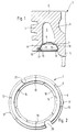
- a head part 1 and a shaft are connected in an articulated manner via a piston pin.
- the shaft and the piston pin are not shown.
- an outer ring wall 3 containing the grooves for the piston rings extends from the bottom 2 of the piston head.
- an annular rib 4 connects hubs 5 to the piston crown 2.
- annular ring Cavity 6 is covered by a wall part designed as a sheet metal ring 7 to form a closed cooling oil chamber.
- This sheet metal ring 7 has an upwardly curved ring surface 8 with collars 9, 10 formed thereon on the outer and inner circumference.
- the sheet metal ring 7 is preloaded on the one hand with its outer collar 8 in a corresponding recess 11 on the inner circumference of the ring wall 3 and on the other hand with its inner collar 10 in a corresponding recess 12 on the outer circumference of the annular rib 4 or the hub 5.
- they In order to be able to elastically deform the collars 9, 10, they have longitudinal slots 13, 14 distributed over the inner and outer circumference, which extend over the entire length of the collars 9, 10.
- the collars 9, 10 are bent toward one another at their open ends 15, 16.
- a nose 17 protruding from the collar 9 is formed on the sheet metal ring 7 and protrudes into a corresponding recess 18 provided in the ring wall 3.
- the sheet metal ring 7 can be made in two parts (parting lines 19) and have recesses 20, 21 for supplying and removing cooling oil.
- the sheet metal ring 7 should be made of a resilient material, e.g. Spring steel.
Landscapes
- Engineering & Computer Science (AREA)
- Chemical & Material Sciences (AREA)
- Combustion & Propulsion (AREA)
- Mechanical Engineering (AREA)
- General Engineering & Computer Science (AREA)
- Physics & Mathematics (AREA)
- Fluid Mechanics (AREA)
- Pistons, Piston Rings, And Cylinders (AREA)
Applications Claiming Priority (5)
| Application Number | Priority Date | Filing Date | Title |
|---|---|---|---|
| DE4039752 | 1990-12-13 | ||
| DE19904039754 DE4039754A1 (de) | 1990-12-13 | 1990-12-13 | Mehrteiliger, gekuehlter kolben fuer verbrennungsmotoren |
| DE4039754 | 1990-12-13 | ||
| DE19904039752 DE4039752A1 (de) | 1990-12-13 | 1990-12-13 | Mehrteiliger, gekuehlter kolben fuer verbrennungsmotoren |
| PCT/DE1991/000928 WO1992010659A1 (de) | 1990-12-13 | 1991-11-23 | Mehrteiliger, gekühlter kolben für verbrennungsmotoren |
Publications (2)
| Publication Number | Publication Date |
|---|---|
| EP0561817A1 EP0561817A1 (en) | 1993-09-29 |
| EP0561817B1 true EP0561817B1 (de) | 1995-04-12 |
Family
ID=25899262
Family Applications (1)
| Application Number | Title | Priority Date | Filing Date |
|---|---|---|---|
| EP91920243A Expired - Lifetime EP0561817B1 (de) | 1990-12-13 | 1991-11-23 | Mehrteiliger, gekühlter kolben für verbrennungsmotoren |
Country Status (6)
| Country | Link |
|---|---|
| US (1) | US5357920A (ja) |
| EP (1) | EP0561817B1 (ja) |
| JP (1) | JP3224389B2 (ja) |
| BR (1) | BR9107164A (ja) |
| DE (1) | DE59105206D1 (ja) |
| WO (1) | WO1992010659A1 (ja) |
Cited By (1)
| Publication number | Priority date | Publication date | Assignee | Title |
|---|---|---|---|---|
| DE102005037175A1 (de) * | 2005-08-06 | 2007-02-08 | Mahle International Gmbh | Kolben für einen Verbrennungsmotor sowie Abdeckring für den Kühlkanal eines solchen Kolbens |
Families Citing this family (27)
| Publication number | Priority date | Publication date | Assignee | Title |
|---|---|---|---|---|
| DE4446726A1 (de) * | 1994-12-24 | 1996-06-27 | Mahle Gmbh | Verfahren zur Herstellung eines einteiligen Kühlkanalkolbens |
| DE19501416A1 (de) * | 1995-01-19 | 1996-07-25 | Kolbenschmidt Ag | Geschmiedeter oder gegossener Kolbenkopf eines mehrteiligen Kolbens |
| US5839352A (en) * | 1996-08-07 | 1998-11-24 | Cummins Engine Company, Inc. | Articulated piston |
| DE19747944A1 (de) * | 1997-10-30 | 1999-05-06 | Mahle Gmbh | Kolben mit zentralem Kühlraum |
| DE19926567A1 (de) | 1999-06-11 | 2000-12-14 | Mahle Gmbh | Gekühlter Kolben für Verbrennungsmotoren |
| DE19926568A1 (de) * | 1999-06-11 | 2000-12-14 | Mahle Gmbh | Gekühlter Kolben für Verbrennungsmotoren |
| US6401595B1 (en) | 2000-10-18 | 2002-06-11 | Caterpillar Inc. | Piston for an internal combustion engine and method of assembly |
| US6938604B2 (en) * | 2003-10-06 | 2005-09-06 | Mahle Gmbh | Cooling channel cover for a one-piece piston of an internal combustion engine |
| US6920860B2 (en) * | 2003-10-06 | 2005-07-26 | Mahle Gmbh | Cooling channel cover for a one-piece piston of an internal combustion engine |
| DE10346822A1 (de) * | 2003-10-06 | 2005-04-21 | Mahle Gmbh | Kolben für einen Verbrennungsmotor |
| DE10346819A1 (de) | 2003-10-06 | 2005-04-21 | Mahle Gmbh | Einteiliger Kolben für einen Verbrennungsmotor |
| US6820582B1 (en) * | 2003-10-06 | 2004-11-23 | Mahle Gmbh | Cooling channel cover for a one-piece piston of an internal combustion engine |
| US6892690B2 (en) * | 2003-10-06 | 2005-05-17 | Mahle Gmbh | Cooling channel cover for a one-piece piston of an internal combustion engine |
| DE102004019010A1 (de) * | 2004-04-20 | 2005-11-17 | Mahle Gmbh | Kühlkanalabdeckung für einen Kolben eines Verbrennungsmotors |
| DE102004019011A1 (de) | 2004-04-20 | 2005-11-17 | Mahle Gmbh | Kühlkanalabdeckung für einen Kolben eines Verbrennungsmotors |
| US7162990B1 (en) | 2005-12-29 | 2007-01-16 | Mahle Technology, Inc. | Two-part piston for an internal combustion engine |
| US8347842B2 (en) * | 2008-02-19 | 2013-01-08 | Federal-Mogul Corporation | Coolable piston for internal combustion engine |
| US7762227B2 (en) * | 2008-02-19 | 2010-07-27 | Federal Mogul Corporation | Coolable piston for internal combustion engine |
| DE102010025507A1 (de) * | 2010-06-29 | 2011-12-29 | Mahle International Gmbh | Kolben für einen Verbrennungsmotor |
| DE102010053925A1 (de) * | 2010-12-09 | 2012-06-14 | Mahle International Gmbh | Kolben für einen Verbrennungsmotor und Verfahren zu seiner Herstellung |
| DE102011013139A1 (de) * | 2011-03-04 | 2012-09-06 | Mahle International Gmbh | Kolben für einen Verbrennungsmotor |
| DE102011076369A1 (de) * | 2011-05-24 | 2012-11-29 | Mahle International Gmbh | Untere Abdeckung eines Kühlkanals eines Kolbens |
| DE102011106381A1 (de) * | 2011-07-04 | 2013-01-10 | Mahle International Gmbh | Kolben für einen Verbrennungsmotor |
| US9429099B2 (en) | 2011-11-14 | 2016-08-30 | Mahle International Gmbh | Piston assembly with multi-piece skirt |
| WO2013074651A1 (en) * | 2011-11-14 | 2013-05-23 | Mahle International Gmbh | Piston assembly with multi-piece skirt |
| DE102012014195A1 (de) * | 2012-07-18 | 2014-01-23 | Mahle International Gmbh | Kolben für einen Verbrennungsmotor |
| US11946434B1 (en) * | 2023-02-08 | 2024-04-02 | Innio Jenbacher Gmbh & Co Og | System and method for enclosing piston cooling gallery |
Family Cites Families (6)
| Publication number | Priority date | Publication date | Assignee | Title |
|---|---|---|---|---|
| US1900521A (en) * | 1931-02-06 | 1933-03-07 | James H Price | Piston head guard |
| US4377967A (en) * | 1981-03-27 | 1983-03-29 | Mack Trucks, Inc. | Two-piece piston assembly |
| DD252638A1 (de) * | 1986-09-17 | 1987-12-23 | Ifa Motorenwerke | Spritzoelgekuehlter eisenkolben fuer hubkolbenbrennkraftmaschinen |
| DE3643039A1 (de) * | 1986-12-17 | 1988-06-30 | Mahle Gmbh | Kuehlbarer tauchkolben fuer verbrennungsmotoren |
| US4986167A (en) * | 1989-05-25 | 1991-01-22 | Caterpillar Inc. | Articulated piston with a cooling recess having a preestablished volume therein |
| BR9005376A (pt) * | 1990-10-18 | 1992-06-16 | Metal Leve Sa | Embolo bipartido com fechamento postico de galeria e processo para sua obtencao |
-
1991
- 1991-11-23 BR BR919107164A patent/BR9107164A/pt not_active IP Right Cessation
- 1991-11-23 EP EP91920243A patent/EP0561817B1/de not_active Expired - Lifetime
- 1991-11-23 US US08/075,548 patent/US5357920A/en not_active Expired - Lifetime
- 1991-11-23 JP JP50026292A patent/JP3224389B2/ja not_active Expired - Lifetime
- 1991-11-23 WO PCT/DE1991/000928 patent/WO1992010659A1/de active IP Right Grant
- 1991-11-23 DE DE59105206T patent/DE59105206D1/de not_active Expired - Lifetime
Cited By (1)
| Publication number | Priority date | Publication date | Assignee | Title |
|---|---|---|---|---|
| DE102005037175A1 (de) * | 2005-08-06 | 2007-02-08 | Mahle International Gmbh | Kolben für einen Verbrennungsmotor sowie Abdeckring für den Kühlkanal eines solchen Kolbens |
Also Published As
| Publication number | Publication date |
|---|---|
| BR9107164A (pt) | 1994-03-01 |
| JPH06503141A (ja) | 1994-04-07 |
| DE59105206D1 (de) | 1995-05-18 |
| JP3224389B2 (ja) | 2001-10-29 |
| US5357920A (en) | 1994-10-25 |
| EP0561817A1 (en) | 1993-09-29 |
| WO1992010659A1 (de) | 1992-06-25 |
Similar Documents
| Publication | Publication Date | Title |
|---|---|---|
| EP0561817B1 (de) | Mehrteiliger, gekühlter kolben für verbrennungsmotoren | |
| EP0481212B1 (de) | Kugelgelenk | |
| DE3904059C2 (ja) | ||
| DE60127008T2 (de) | Kreuzgelenk | |
| DE4430137B4 (de) | Mehrteiliger, gekühlter Kolben für Verbrennungsmotoren | |
| EP3315728B1 (de) | Gedämpfte leitschaufellagerung | |
| EP0475070B1 (de) | Mehrwegeventil | |
| DE202005021716U1 (de) | Nockenwelle | |
| DE3321881A1 (de) | Kupplungsmechanismus, insbesondere fuer kraftfahrzeuge | |
| EP1913250A1 (de) | Kolben für einen verbrennungsmotor sowie abdeckring für den kühlkanal eines solchen kolbens | |
| EP1636474B1 (de) | Verfahren zur herstellung eines einteiligen kolbens für einen verbrennungsmotor | |
| EP3324062A1 (de) | Rotationssystem mit radialer gaslagerung | |
| EP1678417A1 (de) | Kolben f r einen verbrennungsmotor | |
| EP0341480B1 (de) | Montagevorrichtung für Ventilbetätigungselemente von Brennkraftmaschinen | |
| DE2264448A1 (de) | Innendichtung fuer kolben von rotationskolben - brennkraftmaschinen | |
| DE4039754A1 (de) | Mehrteiliger, gekuehlter kolben fuer verbrennungsmotoren | |
| DE2246623A1 (de) | Befestigungsvorrichtung und damit zusammenwirkendes werkzeug | |
| DE602004011811T2 (de) | Kühlkanalabdeckung für einen einstückigen kolben eines verbrennungsmotors | |
| DE4239770C2 (de) | Zweimassenschwungrad | |
| DE3839968A1 (de) | Turbinengehaeuse eines abgasturboladers | |
| EP0525289A1 (de) | Kassettendichtung | |
| DE10329433B4 (de) | Lageranordnung mit einem Lagerträger und wenigstens einem Lager | |
| DE4340035B4 (de) | Mechanischer Tassenstößel | |
| DE19580719B4 (de) | Einteiliger Deckel für einen Kupplungsmechanismus und Kupplungsmechanismus mit einem solchen Deckel | |
| DE19834677A1 (de) | Kugelgelenk, insbesondere für Lenk- und Achsgestänge von Kraftfahrzeugen |
Legal Events
| Date | Code | Title | Description |
|---|---|---|---|
| PUAI | Public reference made under article 153(3) epc to a published international application that has entered the european phase |
Free format text: ORIGINAL CODE: 0009012 |
|
| 17P | Request for examination filed |
Effective date: 19930506 |
|
| AK | Designated contracting states |
Kind code of ref document: A1 Designated state(s): DE FR GB SE |
|
| 17Q | First examination report despatched |
Effective date: 19940912 |
|
| GRAA | (expected) grant |
Free format text: ORIGINAL CODE: 0009210 |
|
| AK | Designated contracting states |
Kind code of ref document: B1 Designated state(s): DE FR GB SE |
|
| REF | Corresponds to: |
Ref document number: 59105206 Country of ref document: DE Date of ref document: 19950518 |
|
| ET | Fr: translation filed | ||
| GBT | Gb: translation of ep patent filed (gb section 77(6)(a)/1977) |
Effective date: 19950525 |
|
| PLBE | No opposition filed within time limit |
Free format text: ORIGINAL CODE: 0009261 |
|
| STAA | Information on the status of an ep patent application or granted ep patent |
Free format text: STATUS: NO OPPOSITION FILED WITHIN TIME LIMIT |
|
| 26N | No opposition filed | ||
| REG | Reference to a national code |
Ref country code: GB Ref legal event code: IF02 |
|
| PGFP | Annual fee paid to national office [announced via postgrant information from national office to epo] |
Ref country code: FR Payment date: 20101209 Year of fee payment: 20 |
|
| PGFP | Annual fee paid to national office [announced via postgrant information from national office to epo] |
Ref country code: DE Payment date: 20101201 Year of fee payment: 20 |
|
| PGFP | Annual fee paid to national office [announced via postgrant information from national office to epo] |
Ref country code: GB Payment date: 20101213 Year of fee payment: 20 Ref country code: SE Payment date: 20101123 Year of fee payment: 20 |
|
| REG | Reference to a national code |
Ref country code: DE Ref legal event code: R071 Ref document number: 59105206 Country of ref document: DE |
|
| REG | Reference to a national code |
Ref country code: DE Ref legal event code: R071 Ref document number: 59105206 Country of ref document: DE |
|
| REG | Reference to a national code |
Ref country code: GB Ref legal event code: PE20 Expiry date: 20111122 |
|
| REG | Reference to a national code |
Ref country code: SE Ref legal event code: EUG |
|
| PG25 | Lapsed in a contracting state [announced via postgrant information from national office to epo] |
Ref country code: GB Free format text: LAPSE BECAUSE OF EXPIRATION OF PROTECTION Effective date: 20111122 |
|
| PG25 | Lapsed in a contracting state [announced via postgrant information from national office to epo] |
Ref country code: DE Free format text: LAPSE BECAUSE OF EXPIRATION OF PROTECTION Effective date: 20111124 |