EP0561591A2 - Verwirbelungsvorrichtung für Verbrennungsgerät - Google Patents
Verwirbelungsvorrichtung für Verbrennungsgerät Download PDFInfo
- Publication number
- EP0561591A2 EP0561591A2 EP93301943A EP93301943A EP0561591A2 EP 0561591 A2 EP0561591 A2 EP 0561591A2 EP 93301943 A EP93301943 A EP 93301943A EP 93301943 A EP93301943 A EP 93301943A EP 0561591 A2 EP0561591 A2 EP 0561591A2
- Authority
- EP
- European Patent Office
- Prior art keywords
- flow
- combustion
- fuel
- enclosure
- combustor
- Prior art date
- Legal status (The legal status is an assumption and is not a legal conclusion. Google has not performed a legal analysis and makes no representation as to the accuracy of the status listed.)
- Withdrawn
Links
- 238000002485 combustion reaction Methods 0.000 claims abstract description 109
- 239000000446 fuel Substances 0.000 claims abstract description 40
- 238000009792 diffusion process Methods 0.000 claims abstract description 28
- 238000000034 method Methods 0.000 claims description 19
- 230000000087 stabilizing effect Effects 0.000 claims description 5
- 239000012530 fluid Substances 0.000 claims description 3
- 238000003491 array Methods 0.000 abstract description 6
- 238000002347 injection Methods 0.000 abstract description 3
- 239000007924 injection Substances 0.000 abstract description 3
- 230000008569 process Effects 0.000 description 7
- 238000011144 upstream manufacturing Methods 0.000 description 7
- UGFAIRIUMAVXCW-UHFFFAOYSA-N Carbon monoxide Chemical compound [O+]#[C-] UGFAIRIUMAVXCW-UHFFFAOYSA-N 0.000 description 4
- 230000008901 benefit Effects 0.000 description 4
- 229910002091 carbon monoxide Inorganic materials 0.000 description 4
- 229930195733 hydrocarbon Natural products 0.000 description 4
- 150000002430 hydrocarbons Chemical class 0.000 description 4
- 230000006641 stabilisation Effects 0.000 description 4
- 238000011105 stabilization Methods 0.000 description 4
- 239000004215 Carbon black (E152) Substances 0.000 description 2
- 230000002708 enhancing effect Effects 0.000 description 2
- 239000000203 mixture Substances 0.000 description 2
- 230000003134 recirculating effect Effects 0.000 description 2
- 230000009467 reduction Effects 0.000 description 2
- 230000001133 acceleration Effects 0.000 description 1
- 230000009471 action Effects 0.000 description 1
- 230000008859 change Effects 0.000 description 1
- 230000001627 detrimental effect Effects 0.000 description 1
- 230000005611 electricity Effects 0.000 description 1
- 239000003344 environmental pollutant Substances 0.000 description 1
- 238000012986 modification Methods 0.000 description 1
- 230000004048 modification Effects 0.000 description 1
- 231100000719 pollutant Toxicity 0.000 description 1
Images

Classifications
-
- F—MECHANICAL ENGINEERING; LIGHTING; HEATING; WEAPONS; BLASTING
- F02—COMBUSTION ENGINES; HOT-GAS OR COMBUSTION-PRODUCT ENGINE PLANTS
- F02C—GAS-TURBINE PLANTS; AIR INTAKES FOR JET-PROPULSION PLANTS; CONTROLLING FUEL SUPPLY IN AIR-BREATHING JET-PROPULSION PLANTS
- F02C3/00—Gas-turbine plants characterised by the use of combustion products as the working fluid
- F02C3/14—Gas-turbine plants characterised by the use of combustion products as the working fluid characterised by the arrangement of the combustion chamber in the plant
-
- F—MECHANICAL ENGINEERING; LIGHTING; HEATING; WEAPONS; BLASTING
- F23—COMBUSTION APPARATUS; COMBUSTION PROCESSES
- F23C—METHODS OR APPARATUS FOR COMBUSTION USING FLUID FUEL OR SOLID FUEL SUSPENDED IN A CARRIER GAS OR AIR
- F23C7/00—Combustion apparatus characterised by arrangements for air supply
- F23C7/002—Combustion apparatus characterised by arrangements for air supply the air being submitted to a rotary or spinning motion
- F23C7/004—Combustion apparatus characterised by arrangements for air supply the air being submitted to a rotary or spinning motion using vanes
-
- F—MECHANICAL ENGINEERING; LIGHTING; HEATING; WEAPONS; BLASTING
- F23—COMBUSTION APPARATUS; COMBUSTION PROCESSES
- F23R—GENERATING COMBUSTION PRODUCTS OF HIGH PRESSURE OR HIGH VELOCITY, e.g. GAS-TURBINE COMBUSTION CHAMBERS
- F23R3/00—Continuous combustion chambers using liquid or gaseous fuel
- F23R3/02—Continuous combustion chambers using liquid or gaseous fuel characterised by the air-flow or gas-flow configuration
- F23R3/04—Air inlet arrangements
- F23R3/10—Air inlet arrangements for primary air
- F23R3/12—Air inlet arrangements for primary air inducing a vortex
- F23R3/14—Air inlet arrangements for primary air inducing a vortex by using swirl vanes
Definitions
- the present invention relates to combustors for turbines and particularly relates to apparatus and methods for enhancing combustion at non-baseload operating conditions in an otherwise lean premixed gutter-stabilized combustion system.
- combustors for turbines.
- One technique known as a diffusion flame process, involves injecting fuel into the air flow through the combustor and burning the fuel as it mixes with the air.
- the advantages of the diffusion flame combustion technique include self-regulation, and flame stability under a wide variety of conditions.
- combustors employing the diffusion combustion process are designed to maintain the flame in a specific location and avoid blow-out and movement either upstream or downstream. Diffusion combustion processes, however, produce a very high flame temperature which, in turn, causes undesirable emissions such as high NO x emissions.
- one method of reducing the high flame temperature in the diffusion combustion process, and hence the level of pollutants is to provide air in excess of that necessary for complete combustion.
- fuel and air are premixed upstream of the burning zone of the combustor in a significantly lean fuel/air mixture.
- the mixture ignites and burns, resulting in a flame temperature that is reduced because of the available excess air.
- gutters are often employed upstream of the combustion zone to create low velocity, recirculating flow regions and hence hold the flame in these gutter wakes downstream of the gutters. Gutters have thus been used in lean premixed combustion processes to stabilize the burning process, while maintaining cooler flame temperatures with lower emissions.
- Turbines are normally operated at baseload conditions in a lean premixed combustion mode at a predetermined fuel/air ratio.
- fuel/air ratios vary across the load.
- any load reduction requires a corresponding reduction in fuel.
- the turbine operates at the baseload condition for maximum efficiency, there are conditions such as ignition, acceleration of the rotor to operating speed, synchronization of the rotor with the generator, or low-load operation, situations where a non-baseload operating condition exists.
- the premixed lean burning process may potentially become unstable and inefficient and approach or cross the lean flammability limit where blow-out occurs. Consequently, at these non-baseload conditions, it has been found necessary to employ the diffusion combustion process rather than the lean premixed combustion process, because the diffusion combustion process is efficient and stable at low loads.
- fuel may be injected directly into the flow, for example, from the gutters or from the hub of the gutters used for the lean premixed operation.
- advantage is taken of the geometry of the lean premixed combustor system for stabilizing the flame to produce flow conditions in the combustor to enhance the non-baseload or low-load burning process using the diffusion combustion process.
- This is accomplished in the present invention by segregating the flow through the combustor into discrete flow fields, each containing only a fraction of the total flow past the gutters which are used for stabilization of the flame in the lean premixed combustion process, and employing the diffusion combustion process in a limited number of the discrete flow fields.
- This aids ignition and low fuel-to-air ratio operation by creating a locally higher fuel-to-air ratio, enabling hotter and more complete combustion to occur than if all of the air were directly involved in the combustion.
- the localized hotter burning produces less carbon monoxide and unburned hydrocarbon emissions, while maintaining flame stability.
- the present invention thus uses the gutters employed in the lean premixed combustion process for flame stabilization to establish the discrete flow fields which afford both flame stability and higher combustion efficiency wafer using the diffusion combustion process in an otherwise fixed geometry combustor for lean premixed combustion operation.
- the gutters are arranged to produce counter-rotating concentric flow fields. That is, the gutters are arranged in the usual radial array for lean premixed combustion operation but are turned or canted at different radial locations to provide flow components at circumferentially opposite directions establishing respective discrete flow fields. Consequently, concentric counter-rotating swirling flow fields are provided within the combustion enclosure. These flow fields form an interface or shear layer which isolates the flow from one another. Direct injection of fuel may therefore be provided into a subset of the overall flow field typically the radially innermost flow field, wherein a diffusion combustion process may be established within the above subset of the total flow field using only a fraction of the total air flow through the combustor. That is, the fuel is directly injected into a zone which has highly turbulent swirling air, and which is isolated from the remainder of the flow through the combustor by a shear layer established between the discrete flow fields.
- one flow field the radially inner flow field
- the radially inner flow field has a higher concentration of gutter area and, hence, a higher blockage of the flow through the combustor. This permits greater recirculation within the downstream flow field and consequently enhanced lame stability and more time for the fuel introduced in the diffusion process to burn.
- a combustor for a turbine comprising an enclosure for receiving a flow of lean premixed fuel and air and combustion thereof in a combustion zone for producing low emissions at baseload operation of the turbine, and an array of gutters disposed in the enclosure upstream of the combustion zone the gutters having an elongated apex and surfaces divergent therefrom extending in a downstream direction in the enclosure for stabilizing the flame in the combustion zone when combusting the premixed fuel and air.
- the gutters are configured and arranged to isolate the flow through the enclosure downstream of the array of gutters into at least two discrete flow fields, each containing a fraction of the total flow past the gutters.
- Means are provided for introducing fuel into one or more of the discrete flow fields during turbine operation at non-baseload operating conditions to create in one discrete fluid flow field combustion by a diffusion process with a locally higher fuel-to-air ratio enabling hotter and more complete combustion at non-baseload conditions.
- a combustor for a turbine comprising an enclosure for receiving a flow of lean premixed fuel and air and combustion thereof in a combustion zone for producing low emissions at baseload operation of the turbine, means in the enclosure for stabilizing the flame in the combustion zone when combusting the premixed fuel and air and means for isolating the flow through the enclosure into at least two discrete flow fields each containing a fraction of the total flow through the enclosure.
- Means are provided for introducing fuel into at least one of the discrete flow fields during turbine operation at non-baseload conditions to create in at least one discrete fluid flow fields combustion by a diffusion process with locally higher fuel-to-air ratio enabling hotter and more complete combustion at lower than baseline operating conditions.
- a method of operating a combustor for a turbine comprising the steps of providing a combustor having an enclosure, a combustion zone and an array of gutters upstream of the combustion zone, supplying a flow of lean, premixed fuel and air past the array of gutters for combustion in the combustion zone affording lean premixed low-emission turbine operation at baseload conditions, forming at least two discrete flow fields in the enclosure downstream of the array of gutters, with each flow field containing a fraction of the total flow past the array of gutters, isolating the flow fields one from the other to form an isolated combustion zone and providing fuel into the isolated combustion zone at non-baseload operating conditions to create a locally higher fuel-to-air ratio in the isolated combustion zone, enabling hotter and more complete combustion therein than if all the flow was involved in combustion in the entire combustion zone.
- a method of operating a combustor for a turbine comprising the steps of providing a combustor having an enclosure and a combustion zone, supplying a flow of lean, premixed fuel and air into the combustion zone for combustion therein thereby affording lean premixed low-emission turbine operation at baseload conditions, forming at least two discrete flow fields in the enclosure, with each flow field containing a fraction of the total flow through the enclosure, isolating the flow fields one from the other to form an isolated combustion zone and providing fuel into the isolated combustion zone at non-baseload operating conditions to create a locally higher fuel-to-air ratio in the isolated combustion zone, enabling hotter and more complete combustion therein than if all the flow was involved in combustion in the entire combustion zone.
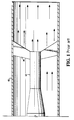
- a combustor of the prior art comprised of a generally cylindrical housing 10 having a central tube 12, which may comprise a fuel injector, and a plurality of radially extending, circumferentially spaced, generally Vee-shaped gutters 14 disposed in the air flow stream indicated by the straight arrows.
- the Vee-shaped gutters have their apexes in the upstream direction with the legs of the Vee-shaped gutter extending at equal angles from the apex in opposite circumferential and downstream directions to provide a turbulent wake or trail downstream of the gutter establishing a recirculation region for stabilizing the flame.
- the premixed fuel and air is provided upstream of the gutters by any suitable means within the area within enclosure 10 outwardly of tube 12 or from within tube 12, or both.
- Lean premixed combustion then occurs in a combustion zone downstream of the gutters.
- the lean premixed combustion mode is highly efficient with reduced emissions at baseload-operations.
- the fixed geometry of the system tends to introduce inefficiencies and higher emissions.
- a fixed geometry, lean premixed combustor system operable at high efficiency and low emissions at baseload conditions, yet enabling combustion by the diffusion process at non-baseload, e.g., lower-than-baseload, operating conditions whereby combustion efficiency and emissions are substantially improved.
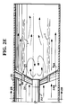
- a combustor having a generally cylindrical enclosure 20, a central axially extending tube 22, which may be used for fuel injection purposes as described hereafter, and a plurality of radially extending, circumferentially spaced, Vee-shaped gutters, arranged in radially inner and outer arrays of gutters, designated 26 and 28, respectively.
- Each of the gutters 26 and 28 is formed in a generally Vee-shaped configuration having an apex ( Figure 2A) 30 and a pair of legs 32 and 34 extending from the apex in the downstream direction of flow through enclosure 20.
- the inner array of Vee-shaped gutters 26, however, are angled or canted such that its leg 34 extends at an angle to the axial direction of flow greater than the angle that the other leg 32 extends relative to the axial direction of flow.
- the leg 32 of the inner array of Vee-shaped gutters 26 extends generally parallel to the axial direction of flow.
- the Vee-shaped gutters 28 of the radially outer array thereof have their legs offset at an angle to the direction of flow.
- the leg 32 of each gutter extends at a greater angle to the axial direction of flow than the leg 34, the latter leg preferably extending generally parallel to the axial direction of flow.
- the Vee-shaped gutters 26 and 28 are arranged such that the inner and outer gutters have legs extending in opposite directions at greater angles to the axial direction of flow than the other legs of the Vee-shaped gutters.
- the gutters are configured and arranged to provide flow components in opposite circumferential directions, as illustrated by the arrows A and B, indicating the circumferential direction of flow downstream of the gutters as a result of their angulation relative to the axial direction of flow.
- two concentric isolated and counter-rotating flow fields or zones are formed downstream of the gutters, each containing a fraction of the total flow past the gutters.
- an intermediate section 24 is provided about the outer ends of the inner array of gutters 26 and at the inner ends of the outer array of gutters 28.
- the circumferentially directed, oppositely rotating concentric flows established by the orientation and arrangement of the Vee-shaped gutters create an interface or shear layer between the two concentric flows downstream of the Vee-shaped gutters, as indicated at 1.
- two discrete flow fields isolated one from the other, each containing a fraction of the total flow past the gutters exists downstream of gutters 26 and 28.
- the generally canted configuration of the inner and outer arrays of gutters 26 and 28 function substantially similarly as Vee-shaped gutters in prior combustion systems using the lean premixed combustion mode. That is, each of the Vee-shaped gutters of both the inner and outer arrays thereof creates a recirculating turbulent wake downstream from the gutter for flame stabilization purposes.
- the swirling action of the counter-rotating flows in the lean premixed mode has no detrimental effect in the lean premixed combustion process.
- fuel may be injected through the central tube 22 directly into an air flow for burning in a diffusion combustion mode in one of the discrete flow fields or zones defined by the inner and outer arrays of gutters 26 and 28, respectively.
- the fuel is preferably injected in the zone defined by the inner array of gutters 26.
- Flame stabilization is enhanced in the diffusion combustion mode by the Vee-shaped gutters.
- a locally higher fuel-to-air ratio is provided in only a portion of the total air flow through the enclosure, enabling hotter and more complete combustion to occur than if all the air flowing through enclosure 20 were directly involved in the combustion.
- the higher localized flame temperature produces less carbon monoxide and unburned hydrocarbon emissions.
- the diffusion combustion mode provides for an isolated combustion zone within only a part of the entire combustion zone used when operating in the lean premixed combustion mode. No change in the geometry of the system is required for operation in either combustion mode.
- the benefits of the present invention are also afforded by the introduction of the diffusion combustion mode in the isolated flow field caused by the inner array of gutters rather than in the flow field generated by the outer array of gutters. Because of the concentrated gutter area along the axis of the combustor, the inner array of gutters afford a higher degree of blockage of air flow and hence provide a greater recirculation of the flow through the combustor in that area. This recirculation provides additional time for the fuel introduced during the diffusion combustion mode to be burned.
- the reverse configuration may be employed, i.e., providing for the diffusion combustion mode in the isolated outer flow field by increasing the blockage, i.e., increasing the number or area, or both, of the outermost array of Vee-shaped gutters 28.
Landscapes
- Engineering & Computer Science (AREA)
- Chemical & Material Sciences (AREA)
- Combustion & Propulsion (AREA)
- Mechanical Engineering (AREA)
- General Engineering & Computer Science (AREA)
- Fluidized-Bed Combustion And Resonant Combustion (AREA)
Applications Claiming Priority (2)
| Application Number | Priority Date | Filing Date | Title |
|---|---|---|---|
| US851776 | 1986-04-14 | ||
| US07/851,776 US5267851A (en) | 1992-03-16 | 1992-03-16 | Swirl gutters for isolating flow fields for combustion enhancement at non-baseload operating conditions |
Publications (2)
| Publication Number | Publication Date |
|---|---|
| EP0561591A2 true EP0561591A2 (de) | 1993-09-22 |
| EP0561591A3 EP0561591A3 (en) | 1993-11-18 |
Family
ID=25311653
Family Applications (1)
| Application Number | Title | Priority Date | Filing Date |
|---|---|---|---|
| EP19930301943 Withdrawn EP0561591A3 (en) | 1992-03-16 | 1993-03-15 | Swirler for combustor |
Country Status (6)
| Country | Link |
|---|---|
| US (1) | US5267851A (de) |
| EP (1) | EP0561591A3 (de) |
| JP (1) | JPH0618035A (de) |
| KR (1) | KR930019990A (de) |
| CN (1) | CN1080044A (de) |
| NO (1) | NO930928L (de) |
Cited By (5)
| Publication number | Priority date | Publication date | Assignee | Title |
|---|---|---|---|---|
| EP0672865A3 (de) * | 1994-03-14 | 1997-05-21 | Gen Electric | Brennstoffdüse einer Turbine mit doppelter Möglichkeit zur Diffusions- und Vormischverbrennung und Verfahren zum Betrieb. |
| US6189320B1 (en) | 1996-12-20 | 2001-02-20 | Siemens Aktiengesellschaft | Burner for fluidic fuels having multiple groups of vortex generating elements |
| DE10154282A1 (de) * | 2001-11-05 | 2003-05-15 | Rolls Royce Deutschland | Vorrichtung zur Kraftstoffeinspritzung in den Strömungs-Nachlauf von Drallschaufeln |
| WO2015023042A1 (ko) * | 2013-08-12 | 2015-02-19 | 삼성테크윈 주식회사 | 선회기 |
| EP3535529A4 (de) * | 2016-11-01 | 2020-05-20 | Beijing Huatsing Gas Turbine & IGCC Technology Co., Ltd. | Vormischbrennstoffdüse für eine gasturbine und brennkammer |
Families Citing this family (25)
| Publication number | Priority date | Publication date | Assignee | Title |
|---|---|---|---|---|
| CH687832A5 (de) * | 1993-04-08 | 1997-02-28 | Asea Brown Boveri | Brennstoffzufuehreinrichtung fuer Brennkammer. |
| CH687347A5 (de) * | 1993-04-08 | 1996-11-15 | Abb Management Ag | Wärmeerzeuger. |
| US5487274A (en) * | 1993-05-03 | 1996-01-30 | General Electric Company | Screech suppressor for advanced low emissions gas turbine combustor |
| US6036480A (en) * | 1996-02-16 | 2000-03-14 | Aos Holding Company | Combustion burner for a water heater |
| US6301875B1 (en) * | 2000-05-31 | 2001-10-16 | Coen Company, Inc. | Turbine exhaust gas duct heater |
| US20040007056A1 (en) * | 2001-08-06 | 2004-01-15 | Webb Cynthia C. | Method for testing catalytic converter durability |
| CA2454249A1 (en) * | 2001-08-06 | 2003-02-20 | Southwest Research Institute | Method and apparatus for testing catalytic converter durability |
| US7741127B2 (en) * | 2001-08-06 | 2010-06-22 | Southwest Research Institute | Method for producing diesel exhaust with particulate material for testing diesel engine aftertreatment devices |
| US7175422B2 (en) * | 2001-08-06 | 2007-02-13 | Southwest Research Institute | Method for accelerated aging of catalytic converters incorporating injection of volatilized lubricant |
| US6983645B2 (en) * | 2002-08-06 | 2006-01-10 | Southwest Research Institute | Method for accelerated aging of catalytic converters incorporating engine cold start simulation |
| US7412335B2 (en) * | 2002-08-06 | 2008-08-12 | Southwest Research Institute | Component evaluations using non-engine based test system |
| US7212926B2 (en) * | 2002-08-06 | 2007-05-01 | Southwest Research Institute | Testing using a non-engine based test system and exhaust product comprising alternative fuel exhaust |
| US7299137B2 (en) | 2002-08-06 | 2007-11-20 | Southwest Research Institute | Method for drive cycle simulation using non-engine based test system |
| WO2006101991A2 (en) | 2005-03-17 | 2006-09-28 | Southwest Research Institute | Mass air flow compensation for burner-based exhaust gas generation system |
| US7748976B2 (en) * | 2005-03-17 | 2010-07-06 | Southwest Research Institute | Use of recirculated exhaust gas in a burner-based exhaust generation system for reduced fuel consumption and for cooling |
| US20070039381A1 (en) * | 2005-08-05 | 2007-02-22 | Timmons Suzanne A | Secondary Air Injector For Use With Exhaust Gas Simulation System |
| WO2007119115A2 (en) * | 2005-12-14 | 2007-10-25 | Rolls-Royce Power Engineering Plc | Gas turbine engine premix injectors |
| DE102007043626A1 (de) | 2007-09-13 | 2009-03-19 | Rolls-Royce Deutschland Ltd & Co Kg | Gasturbinenmagerbrenner mit Kraftstoffdüse mit kontrollierter Kraftstoffinhomogenität |
| RU2454607C1 (ru) * | 2011-02-01 | 2012-06-27 | Федеральное государственное унитарное предприятие "Центральный аэрогидродинамический институт имени профессора Н.Е. Жуковского" (ФГУП "ЦАГИ") | Способ стабилизации процесса горения топлива в камере сгорания и камера сгорания прямоточного воздушно-реактивного двигателя летательного аппарата |
| CN103134078B (zh) * | 2011-11-25 | 2015-03-25 | 中国科学院工程热物理研究所 | 一种阵列驻涡燃料-空气预混器 |
| CN103411236B (zh) * | 2013-09-01 | 2015-02-25 | 北京航空航天大学 | 一种开孔侧裙板式值班火焰稳定器 |
| CN105953242A (zh) * | 2016-05-30 | 2016-09-21 | 江苏沃尔特环保有限公司 | 一种内燃式沼气焚烧火炬 |
| CN105953241A (zh) * | 2016-05-30 | 2016-09-21 | 江苏沃尔特环保有限公司 | 一种高效燃烧的内燃式沼气焚烧火炬 |
| CN108800205B (zh) * | 2018-04-24 | 2020-04-24 | 南京航空航天大学 | 一种旋流加力/冲压燃烧室 |
| CN113701191B (zh) * | 2021-09-01 | 2022-06-24 | 南昌航空大学 | 一种交错导流中缝式v型火焰稳定器 |
Family Cites Families (13)
| Publication number | Priority date | Publication date | Assignee | Title |
|---|---|---|---|---|
| US1102510A (en) * | 1911-07-15 | 1914-07-07 | Babcock & Wilcox Co | Apparatus for burning finely-divided fuel. |
| US2587140A (en) * | 1948-08-28 | 1952-02-26 | Steel Products Inc | Diffuser head for fluid fuel burners |
| NL98183C (de) * | 1954-11-24 | |||
| US3031012A (en) * | 1957-12-27 | 1962-04-24 | Gen Thermique Procedes Brola S | Combustion apparatus |
| US3605405A (en) * | 1970-04-09 | 1971-09-20 | Gen Electric | Carbon elimination and cooling improvement to scroll type combustors |
| US3713588A (en) * | 1970-11-27 | 1973-01-30 | Gen Motors Corp | Liquid fuel spray nozzles with air atomization |
| US3703259A (en) * | 1971-05-03 | 1972-11-21 | Gen Electric | Air blast fuel atomizer |
| GB1421399A (en) * | 1972-11-13 | 1976-01-14 | Snecma | Fuel injectors |
| US4160640A (en) * | 1977-08-30 | 1979-07-10 | Maev Vladimir A | Method of fuel burning in combustion chambers and annular combustion chamber for carrying same into effect |
| DE3766807D1 (de) * | 1986-11-25 | 1991-01-31 | Gen Electric | Kombinierter diffusions- und vormischpilotbrenner. |
| JPH076630B2 (ja) * | 1988-01-08 | 1995-01-30 | 株式会社日立製作所 | ガスタービン燃焼器 |
| JPH0293210A (ja) * | 1988-09-30 | 1990-04-04 | Hitachi Ltd | ガスタービン燃焼器 |
| US5095696A (en) * | 1990-01-02 | 1992-03-17 | General Electric Company | Asymmetric flameholder for gas turbine engine afterburner |
-
1992
- 1992-03-16 US US07/851,776 patent/US5267851A/en not_active Expired - Fee Related
-
1993
- 1993-02-23 KR KR1019930002495A patent/KR930019990A/ko not_active Withdrawn
- 1993-03-10 JP JP5048467A patent/JPH0618035A/ja not_active Withdrawn
- 1993-03-13 CN CN93103081A patent/CN1080044A/zh active Pending
- 1993-03-15 NO NO93930928A patent/NO930928L/no unknown
- 1993-03-15 EP EP19930301943 patent/EP0561591A3/en not_active Withdrawn
Cited By (7)
| Publication number | Priority date | Publication date | Assignee | Title |
|---|---|---|---|---|
| EP0672865A3 (de) * | 1994-03-14 | 1997-05-21 | Gen Electric | Brennstoffdüse einer Turbine mit doppelter Möglichkeit zur Diffusions- und Vormischverbrennung und Verfahren zum Betrieb. |
| US6189320B1 (en) | 1996-12-20 | 2001-02-20 | Siemens Aktiengesellschaft | Burner for fluidic fuels having multiple groups of vortex generating elements |
| DE10154282A1 (de) * | 2001-11-05 | 2003-05-15 | Rolls Royce Deutschland | Vorrichtung zur Kraftstoffeinspritzung in den Strömungs-Nachlauf von Drallschaufeln |
| US6901756B2 (en) | 2001-11-05 | 2005-06-07 | Rolls-Royce Deutschland Ltd & Co Kg | Device for the injection of fuel into the flow wake of swirler vanes |
| WO2015023042A1 (ko) * | 2013-08-12 | 2015-02-19 | 삼성테크윈 주식회사 | 선회기 |
| US9851098B2 (en) | 2013-08-12 | 2017-12-26 | Hanwha Techwin Co., Ltd. | Swirler |
| EP3535529A4 (de) * | 2016-11-01 | 2020-05-20 | Beijing Huatsing Gas Turbine & IGCC Technology Co., Ltd. | Vormischbrennstoffdüse für eine gasturbine und brennkammer |
Also Published As
| Publication number | Publication date |
|---|---|
| NO930928L (no) | 1993-09-17 |
| US5267851A (en) | 1993-12-07 |
| JPH0618035A (ja) | 1994-01-25 |
| EP0561591A3 (en) | 1993-11-18 |
| NO930928D0 (no) | 1993-03-15 |
| CN1080044A (zh) | 1993-12-29 |
| KR930019990A (ko) | 1993-10-19 |
Similar Documents
| Publication | Publication Date | Title |
|---|---|---|
| US5267851A (en) | Swirl gutters for isolating flow fields for combustion enhancement at non-baseload operating conditions | |
| US5203796A (en) | Two stage v-gutter fuel injection mixer | |
| EP0453178B1 (de) | Katalytische Gasturbinenbrennkammer mit Vorbrenner und niedrigem NOX-Ausstoss | |
| JP5364275B2 (ja) | 燃焼システムにおけるNOxエミッションを低減するのを可能にするための方法及びシステム | |
| US5857339A (en) | Combustor flame stabilizing structure | |
| US6951108B2 (en) | Gas turbine engine combustor can with trapped vortex cavity | |
| JP3312152B2 (ja) | 低NOx燃焼 | |
| JP2597785B2 (ja) | ガスタービン燃焼器用空気燃料混合器 | |
| EP0878665B1 (de) | Emissionsarmes Verbrennungssystem für Gasturbinentriebwerke | |
| CA1126519A (en) | Method and apparatus for reducing nitrous oxide emissions from combustors | |
| EP0957311A2 (de) | Gasturbinenbrennkammer | |
| US6609377B2 (en) | Multiple injector combustor | |
| JP4191298B2 (ja) | 燃焼装置のための燃料/空気混合装置 | |
| JPS5826498B2 (ja) | ガスタ−ビンエンジン用燃焼装置 | |
| JPH10132278A (ja) | ガスタービン | |
| EP0773410B1 (de) | Kraftstoff-Luft Mischrohr | |
| JPH06213450A (ja) | 燃料噴射ノズル | |
| JP2004534199A (ja) | サイクロン燃焼器 | |
| JP3346034B2 (ja) | ガスタービン用燃焼装置 | |
| RU2106578C1 (ru) | Трубчато-кольцевая камера сгорания газотурбинной энергетической установки | |
| RU2802115C1 (ru) | Камера сгорания газотурбинной установки | |
| JPH08285221A (ja) | 窒素酸化物低発生燃焼方法及び装置 |
Legal Events
| Date | Code | Title | Description |
|---|---|---|---|
| PUAI | Public reference made under article 153(3) epc to a published international application that has entered the european phase |
Free format text: ORIGINAL CODE: 0009012 |
|
| AK | Designated contracting states |
Kind code of ref document: A2 Designated state(s): CH DE FR GB IT LI NL SE |
|
| PUAL | Search report despatched |
Free format text: ORIGINAL CODE: 0009013 |
|
| AK | Designated contracting states |
Kind code of ref document: A3 Designated state(s): CH DE FR GB IT LI NL SE |
|
| STAA | Information on the status of an ep patent application or granted ep patent |
Free format text: STATUS: THE APPLICATION IS DEEMED TO BE WITHDRAWN |
|
| 18D | Application deemed to be withdrawn |
Effective date: 19940519 |