EP0560685B1 - Tendeur pour courroie et système de transmission comprenant un tel tendeur - Google Patents
Tendeur pour courroie et système de transmission comprenant un tel tendeur Download PDFInfo
- Publication number
- EP0560685B1 EP0560685B1 EP93400627A EP93400627A EP0560685B1 EP 0560685 B1 EP0560685 B1 EP 0560685B1 EP 93400627 A EP93400627 A EP 93400627A EP 93400627 A EP93400627 A EP 93400627A EP 0560685 B1 EP0560685 B1 EP 0560685B1
- Authority
- EP
- European Patent Office
- Prior art keywords
- tensioning device
- piston
- tensioner
- fluid
- belt
- Prior art date
- Legal status (The legal status is an assumption and is not a legal conclusion. Google has not performed a legal analysis and makes no representation as to the accuracy of the status listed.)
- Expired - Lifetime
Links
- 230000005540 biological transmission Effects 0.000 title claims description 14
- 239000012530 fluid Substances 0.000 claims description 32
- 238000013016 damping Methods 0.000 claims description 16
- 238000005086 pumping Methods 0.000 claims description 9
- 229920001971 elastomer Polymers 0.000 claims description 3
- 239000013536 elastomeric material Substances 0.000 claims description 3
- 230000000284 resting effect Effects 0.000 claims 1
- 239000003921 oil Substances 0.000 description 9
- 230000007423 decrease Effects 0.000 description 5
- 230000006835 compression Effects 0.000 description 3
- 238000007906 compression Methods 0.000 description 3
- 239000011248 coating agent Substances 0.000 description 2
- 238000000576 coating method Methods 0.000 description 2
- 125000004122 cyclic group Chemical group 0.000 description 2
- 238000005461 lubrication Methods 0.000 description 2
- 239000002480 mineral oil Substances 0.000 description 2
- 238000003825 pressing Methods 0.000 description 2
- 229920000459 Nitrile rubber Polymers 0.000 description 1
- 229910000831 Steel Inorganic materials 0.000 description 1
- 238000010073 coating (rubber) Methods 0.000 description 1
- 238000006073 displacement reaction Methods 0.000 description 1
- 238000009826 distribution Methods 0.000 description 1
- 230000005284 excitation Effects 0.000 description 1
- 238000009434 installation Methods 0.000 description 1
- 239000007788 liquid Substances 0.000 description 1
- 238000004519 manufacturing process Methods 0.000 description 1
- 230000000873 masking effect Effects 0.000 description 1
- 235000010446 mineral oil Nutrition 0.000 description 1
- 238000000926 separation method Methods 0.000 description 1
- 229920002545 silicone oil Polymers 0.000 description 1
- 239000010959 steel Substances 0.000 description 1
Images




Classifications
-
- F—MECHANICAL ENGINEERING; LIGHTING; HEATING; WEAPONS; BLASTING
- F16—ENGINEERING ELEMENTS AND UNITS; GENERAL MEASURES FOR PRODUCING AND MAINTAINING EFFECTIVE FUNCTIONING OF MACHINES OR INSTALLATIONS; THERMAL INSULATION IN GENERAL
- F16H—GEARING
- F16H7/00—Gearings for conveying rotary motion by endless flexible members
- F16H7/08—Means for varying tension of belts, ropes or chains
- F16H7/10—Means for varying tension of belts, ropes or chains by adjusting the axis of a pulley
- F16H7/12—Means for varying tension of belts, ropes or chains by adjusting the axis of a pulley of an idle pulley
- F16H7/1209—Means for varying tension of belts, ropes or chains by adjusting the axis of a pulley of an idle pulley with vibration damping means
- F16H7/1236—Means for varying tension of belts, ropes or chains by adjusting the axis of a pulley of an idle pulley with vibration damping means of the fluid and restriction type, e.g. dashpot
-
- F—MECHANICAL ENGINEERING; LIGHTING; HEATING; WEAPONS; BLASTING
- F16—ENGINEERING ELEMENTS AND UNITS; GENERAL MEASURES FOR PRODUCING AND MAINTAINING EFFECTIVE FUNCTIONING OF MACHINES OR INSTALLATIONS; THERMAL INSULATION IN GENERAL
- F16H—GEARING
- F16H7/00—Gearings for conveying rotary motion by endless flexible members
- F16H7/08—Means for varying tension of belts, ropes or chains
- F16H2007/0802—Actuators for final output members
- F16H2007/0806—Compression coil springs
-
- F—MECHANICAL ENGINEERING; LIGHTING; HEATING; WEAPONS; BLASTING
- F16—ENGINEERING ELEMENTS AND UNITS; GENERAL MEASURES FOR PRODUCING AND MAINTAINING EFFECTIVE FUNCTIONING OF MACHINES OR INSTALLATIONS; THERMAL INSULATION IN GENERAL
- F16H—GEARING
- F16H7/00—Gearings for conveying rotary motion by endless flexible members
- F16H7/08—Means for varying tension of belts, ropes or chains
- F16H7/0848—Means for varying tension of belts, ropes or chains with means for impeding reverse motion
- F16H2007/0859—Check valves
-
- F—MECHANICAL ENGINEERING; LIGHTING; HEATING; WEAPONS; BLASTING
- F16—ENGINEERING ELEMENTS AND UNITS; GENERAL MEASURES FOR PRODUCING AND MAINTAINING EFFECTIVE FUNCTIONING OF MACHINES OR INSTALLATIONS; THERMAL INSULATION IN GENERAL
- F16H—GEARING
- F16H7/00—Gearings for conveying rotary motion by endless flexible members
- F16H7/08—Means for varying tension of belts, ropes or chains
- F16H2007/0889—Path of movement of the finally actuated member
- F16H2007/0891—Linear path
Definitions
- the invention relates mainly to a tensioner for transmission belt, in particular for transmission belt power, for example striated or trapezoidal, and for so-called toothed belt distribution in the automotive industry as well as a transmission system comprising such a tensioner.
- This device comprises a tensioning roller cooperating with the belt, a return spring, a damping device comprising a first variable volume chamber located inside the return spring covered by a rubber sheath and a second volume chamber variable located in the extension of this spring, the two chambers communicating via a valve to obtain damping.
- the size of the second chamber is not negligible and, moreover, the spring relaxes when a decrease in tension occurs belt, which further increases the size of this device.
- US-A-4,790,801 describes a hydraulic tensioner for belt comprising a cylinder and a piston forming an internal chamber variable volume and an external chamber coaxial with the internal chamber.
- the internal chamber and the external chamber are connected by a ball valve unidirectional of large dimensions.
- an object of the present invention to supply a belt tensioner, in particular for a transmission transmission belt power, allowing to obtain high levels of damping, especially when the mechanical tension in the belt increases.
- a tensioner comprising two chambers filled with a fluid, in particular with oil and a passage calibrated small diameter allowing fluid flow between the two rooms with significant damping.
- the implementation of a passage calibrated allows a flow substantially independent of the conditions external, including temperature, including flow turbulent.
- the tensioner according to the present invention comprises a second fluid passage between the two chambers, with an area of more important passage, this second passage not being advantageously accessible to the fluid only for a flow caused by the reduction of the mechanical tension of the belt.
- the main object of the invention is a tensioner for belt comprising two fixing means, in particular connected yokes mechanically by a coil spring and two coaxial chambers containing fluid, hydraulically connected by a connection comprising a passage for the flow of fluid from one chamber into the other, generated by pumping means when the distance between the two fixing means, a first of the two chambers containing fluid is radially external to a second of the two chambers containing fluid which is radially internal, the internal chamber extending over part of the height of the external chamber, the internal chamber is delimited radially by a rigid cylinder, characterized in that the passage of fluid flow has a calibrated section which determines the damping and which is arranged in a piston of the means for pumping the fluid and in a valve opening when the tensioner fixing means move away mutually and closing when the fastening means are brought together of the tensioner, and in that the outer chamber is delimited radially by, on the one hand, by the external wall of the cylinder and, on the other hand, by a
- the invention also relates to a tensioner, characterized in what it includes, in the connection of the two chambers, a valve having openings capable of being at least partially masked when the fluid flows from the internal chamber to the external chamber and likely to be discovered during the flow of the fluid from the outer chamber to the inner chamber.
- the invention also relates to a tensioner, characterized in that the valve is constituted by a movable plate in the shape of a star, the concealable openings being disposed at its periphery.
- the invention also relates to a tensioner, characterized in that the valve includes a flat star-shaped part secured to a bowl, in particular a bowl with a flat bottom and a cylindrical wall connected by a circular wall seen in cross section.
- the invention also relates to a tensioner, characterized in that the pumping means include a piston separating the two chambers and whose diameter is slightly less than the cylinder bore to allow fluids to flow between the piston and the cylinder.
- the invention also relates to a tensioner, characterized in what fixing the ends of the coil spring on the means of fixing the tensioner as well as the seal between the ends of the sheath and the tensioner fixing means are provided by sockets crimped on these fixing means.
- the invention also relates to a tensioner, characterized in that its cohesion is ensured by the cylinder and the pumping means, in particular by a piston rod.
- the invention also relates to a tensioner, characterized in that the valve is provided with a return spring to a rest position in which the maskable openings are masked.
- the invention also relates to a tensioner, characterized in what it includes means for prestressing the spring, including a piston stop ring.
- the invention also relates to a tensioner, characterized in what it has a fluid flow line between the two chambers, formed in the piston.
- the invention also relates to a tensioner, characterized in that the pipeline has a radial channel opening near to the upper end of the piston connected by an axial channel to a calibrated lumen arranged at the base of the piston.
- the invention also relates to a system for transmission for engine comprising a belt and at least two pulleys, characterized in that it comprises a tensioner, according to the invention, fixed by a first end to an engine block and hooked at its end opposite to a lever mounted pivoting about an axis and which carries at its other end a roller pressing on the belt, the roller and the tensioner fixing on the block motor on the same side of the belt.
- a tensioner according to the invention, fixed by a first end to an engine block and hooked at its end opposite to a lever mounted pivoting about an axis and which carries at its other end a roller pressing on the belt, the roller and the tensioner fixing on the block motor on the same side of the belt.
- FIGS. 1 to 8 the same references have been used for designate the same elements.
- FIG. 1 illustrates, very schematically, a power transmission system in which a belt 1 cooperates with the flanges of pulleys 2 and 3 integral in rotation of driven trees and with the flanges of a pulley 4 secured to a tree driving, for example the crankshaft of an automobile engine, truck, agricultural machine or the like.
- a tensioner 5 hooked at eye level 6 to a lever 7, pivotally mounted at one of its ends around an axis 8 and which carries at its other end a roller 9 swiveling around an axis 10 pressing the belt 1.
- the tensioner 5, the eye 11 opposite the eye 6 is fixed to the block motor not shown, is intended to catch the elongation of the belt 1 in order to avoid it sliding relative to the flanges of the pulleys, on the one hand, and on the other hand, to dampen the vibrations generated in the belt 1 by cyclic irregularities in engine speed, in particular at idle, or during jolts generated by the starting and / or stopping of devices driven by shafts secured to pulleys 2 and 3.
- the point of attachment of the tensioner 5 on the block motor and roller 9 are on the same side of the belt so that that a decrease in the tension of the belt 1 causes an increase of the distance between eyes 6 and 11.
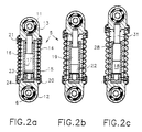
- the tensioner 5 illustrated in FIG. 2 comprises a yoke lower 12 comprising the eye 6 and an upper yoke 13 comprising the eye 11 between which extends a coil spring 14 secured by coating with a sheath made of elastomeric material 15, for example nitrile rubber and which forms the side wall of an external chamber 16 filled with fluid, in particular a mineral oil ensuring good lubrication, a silicone oil whose viscosity varies little with temperature, or liquid and gas.
- fluid in particular a mineral oil ensuring good lubrication, a silicone oil whose viscosity varies little with temperature, or liquid and gas.
- the outer chamber 16 substantially coaxial to the internal chamber 18 is delimited radially inside by the wall external of the cylinder 17 and outside by the sheath 15 coating the spring 14.
- the external chamber 16 extends over the entire height (variable) of the tensioner 5, between the yokes 12 and 13, while the internal chamber 18 has a height less than the height of the tensioner 5 in its normal working position illustrated in FIG. 2b.
- the volume of the internal chamber 18 decreases as a result of the descent of the piston 15, when the yokes 12 and 13 are brought together.
- the seal between the sheath 15 and the yokes 12 and 13 is provided by sockets 20 and 21 crimped on semi joints O-rings provided on the external face of the sheath 15.
- the internal chamber 18 communicates in its lower part with the external chamber 16 via a valve 22, a chimney 23 and radial lights 24 formed in a seat 25 of the valve 22, that you can see better in Figure 3.
- the valve 22 has the maskable lights 26 and, advantageously, at least one light calibrated non-maskable 27.
- the calibrated non-maskable light 27 is disposed at the entrance to a pipe connecting the internal chamber 18 to the external chamber 16, formed in the piston 19.
- the valve 22 is a flat plate in the shape of a star provided in its center of a calibrated hole 27.
- FIG. 7 we can see a variant of advantageous embodiment of the valve according to the present invention comprising a upper flat star-shaped part connected to a bowl 42 comprising a flat bottom 43 disposed orthogonally to a cylindrical wall 44.
- the passage 45 between the wall 44 and the wall 43 forms an arc of a circle.
- the valve of Figure 7 is adapted to cooperate with a conical seat. In in such a case, a slight lifting of the valve releases passage sections important allowing the oil to rise more freely, and thus ensuring faster tension of the belt.
- the spring 14 is prestressed in compression.
- the cylinder 17 is provided in its upper part a stop ring 28 limiting during its ascent the stroke of the piston 19, as shown in Figure 2c.
- the tension of the belt 1 transmitted by the roller 9 and the lever arm 7 compresses the spring 14 and ensures the descent of the piston 19 as illustrated in FIG. 2b in the normal working position.
- the maximum compression position is illustrated in FIG. 2a, the face lower of the piston 19 located in the immediate vicinity of the valve 22.
- the amortization during the rise in the tension in the belt 1 and as a result of the bringing together of the eyes 6 and 11, is very important, while the depreciation is low or negligible when decrease in the tension of the belt 1 with the separation of the eyes 6 and 11, which allows you to catch the belt tension as quickly as possible.
- This kind of operation is illustrated more particularly in FIG. 3.
- the valve 22 a advantageously, a vertical play.
- the spring is compressed, symbolized in FIG. 3a, by the arrow 34, the valve 22 is pressed against its seat 25, which masks the maskable openings 26 at its periphery and leaves one or more calibrated openings 27 uncovered.
- fluid through the opening or calibrated openings 27, illustrated by arrows in Figure 3a, causes the desired damping.
- the fluid flows from the internal chamber 18 in the external chamber 16.
- the depreciation is caused by the flow of fluid between the cylinder 17 and the piston 19 by a calibrated clearance.
- a spring 30 presses the valve 22 on the seat 25 by masking the concealable openings 26.
- the ascent of the piston 19 drives the valve 22 towards the top of the figure, which allows rapid pressure balancing between the external chamber 16 and the internal chamber 18.
- the spring 30 makes it possible to reduce the time necessary for closing the maskable openings 26 because the valve is at rest on seat 25 or closer to that seat.
- the cohesion of the tensioner 5 according to the present invention is ensured by its hydraulic members.
- a rod 31 of the piston 19 is secured to the yoke 13 while the seat 25 of the valve 22 secured to the cylinder 17 is anchored in the yoke 12.
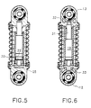
- An example advantageous of such a fixing is illustrated in FIG. 6, in which the upper end of the rod 31 of the piston 19 is provided with a shoulder 32 while the lower part of the seat 25 is provided with a shoulder 33.
- the external chamber 16 can be filled with a gas under a pressure capable of being supported by the sheath 15. It is possible also fill the external chamber 16 with any compressible fluid compatible with the oil filling the internal chamber 18.
- the tensioner has advantageously a valve 22 of FIG. 7 as well as a piston 19 comprising a line 40 allowing the flow of oil from the internal chamber 18 towards the external chamber 16.
- the pipe has a calibrated light 27 located at the bottom of an element conical 46 arranged at the lower part of the piston 19.
- the pipe 40 mainly comprises a channel located along the axis of the piston 19 connected by a transverse channel 47 to the external chamber 16. The pipe 40 allows the flow of fluid from chamber 18 to chamber 16 with passage of the relaxed configuration of FIG. 8d at the compressed condition illustrated on Figure 8a.
- FIG. 8 presents many advantages.
- the implementation of the valve 22 of FIG. 7 associated to a conical seat 48 allows an extremely rapid flow of the the outer chamber to the inner chamber when the belt 1 expands.
- the filling of the internal chamber 18 is not likely to be disturbed by cavitation of the oil at the outlet of the calibrated orifice 27. This is avoided thus filling the internal chamber 18 with a gas phase disrupting depreciation.
- the oil aspirated is healthy, because it is far from the zone which can be disturbed at the outlet of the pipe 47.
- the Figure 8 tensioner is self-priming since a gas possibly present in the internal chamber 18 is naturally evacuated upwards by through line 40. So, on the one hand, we need to take less precautions when assembling the tensioner of figure 8 than with a tensioner of Figure 2, and, on the other hand, the appearance of a gas in the chamber internal 18, during tensioner operation, does not disturb sustainably its functioning.
- the tensioner of Figure 8 is likely to operate under more severe conditions of solicitation with efforts greater damping, a greater amplitude of displacements and higher excitation frequencies. It requires less belt 1 and its lifespan is improved compared to the variant in FIG. 2.
- the tensioner according to the present invention can be adapted to depreciation rate desired by the choice of the passage section of the 27 calibrated opening. A large section reduces the depreciation rate while a weak section leads to high damping.
- tensioners provided with openings calibrated 27 of large diameter and / or large clearances between the cylinder 17 and the piston 19 which results in weak or even negligible damping, do not depart from the scope of the present invention.
- the tensioner 5 has a mounting direction imposed, the valve 22 being located in its lower part. In the case otherwise, pressurized air or gas would be drawn in first when the opening of the valve does not allow the filling of the internal chamber 18. It is, however, of course, that a tensioner having no sense of imposed assembly does not depart from the scope of the present invention.
Landscapes
- Engineering & Computer Science (AREA)
- General Engineering & Computer Science (AREA)
- Mechanical Engineering (AREA)
- Devices For Conveying Motion By Means Of Endless Flexible Members (AREA)
- General Details Of Gearings (AREA)
Description
- la figure 1 est une vue schématique d'un système de transmission de puissance par courroie selon l'invention ;
- la figure 2 comporte trois coupes longitudinales d'un premier exemple de réalisation du tendeur selon la présente invention ;
- la figure 3 comporte deux vues en coupe d'un détail de réalisation du tendeur selon la présente invention ;
- la figure 4 est une vue de dessus d'un premier exemple de réalisation d'un clapet susceptible d'être mis en oeuvre dans le tendeur selon la présente invention ;
- la figure 5 est une vue en coupe longitudinale d'un deuxième exemple de réalisation du tendeur selon la présente invention ;
- la figure 6 est une coupe longitudinale d'un troisième exemple de réalisation du tendeur selon la présente invention ;
- la figure 7 comporte des vues d'un deuxième exemple de réalisation d'un clapet susceptible d'être mis en oeuvre dans le tendeur selon la présente invention ;
- la figure 8 comporte deux coupes longitudinales d'un troisième exemple de réalisation d'un tendeur selon la présente invention.
Claims (12)
- Tendeur pour courroie (1) comportant deux moyens de fixation, notamment des chapes (12,13) reliées mécaniquement par un ressort à boudin (14) et deux chambres (16,18) coaxiales contenant du fluide, reliées hydrauliquement par une connexion (23,24) comportant un passage pour l'écoulement du fluide d'une chambre dans l'autre, engendré par des moyens de pompage (19) lors d'une variation de la distance entre les deux moyens de fixation, une première (16) des deux chambres (16,18) contenant du fluide est radialement externe par rapport à une seconde (18) des deux chambres (16,18) contenant du fluide qui est radialement interne, la chambre interne (18) s'étendant sur une partie de la hauteur de la chambre externe (16), la chambre interne (18) est délimitée radialement par un cylindre rigide (17), caractérisé en ce que le passage d'écoulement du fluide a une section calibrée (26,27) qui détermine l'amortissement et qui est aménagé dans un piston (19) des moyens de pompage du fluide et dans un clapet s'ouvrant lorsque les moyens (12,13) de fixation du tendeur s'éloignent (29) mutuellement et se refermant lors du rapprochement des moyens de fixation du tendeur, et en ce que la chambre externe (16) est délimitée radialement par, d'une part, par la paroi externe du cylindre (17) et, d'autre part, par une gaine (15) en matériau élastomère, notamment en caoutchouc enrobant le ressort à boudin (14) et formant l'enveloppe externe du tendeur.
- Tendeur selon la revendication 1, caractérisé en ce qu'il comporte, dans la connexion des deux chambres (16,18), un clapet (22) comportant des ouvertures (26) susceptibles d'être au moins partiellement masquées lors de l'écoulement du fluide de la chambre interne (18) vers la chambre externe (16) et susceptibles d'être découvertes lors de l'écoulement du fluide de la chambre externe (16) vers la chambre interne (18).
- Tendeur selon la revendication 2, caractérisé en ce que le clapet (22) est constitué par une plaque mobile en forme d'étoile, les ouvertures masquables (26) étant disposées à sa périphérie.
- Tendeur selon la revendication 1 ou 2, caractérisé en ce que le clapet (22) comprend une partie plane en forme d'étoile (41) solidarisée avec une cuvette (42), notamment une cuvette à fond plat (43) et à paroi cylindrique (44) reliée par une paroi (45) circulaire vue en coupe transversale.
- Tendeur selon l'une quelconque des revendications précédentes, caractérisé en ce que les moyens de pompage comportent un piston (19) séparant les deux chambres (16,18) et dont le diamètre est légèrement inférieur à l'alésage du cylindre (17) pour permettre un écoulement des fluides entre le piston (19) et le cylindre (17).
- Tendeur selon la revendication 1, 2, 3, 4 ou 5, caractérisé en ce que la fixation des extrémités du ressort à boudin (14) sur les moyens de fixation (12,13) du tendeur (5) ainsi que l'étanchéité entre les extrémités de la gaine (15) et les moyens de fixation (12,13) du tendeur (5) sont assurées par des douilles (20,21) serties sur ces moyens de fixation (12,13).
- Tendeur selon l'une quelconque des revendications 1 à 6, caractérisé en ce que le cylindre rigide (17) séparant radialement la chambre interne de la chambre externe et les moyens de pompage, notamment une tige (31) du piston (19), assurent la cohésion du tendeur.
- Tendeur selon l'une quelconque des revendications précédentes, caractérisé en ce que le clapet (22) est muni d'un ressort de rappel (30) vers une position de repos dans laquelle les ouvertures masquables (26) sont masquées.
- Tendeur selon l'une quelconque des revendications précédentes, caractérisé en ce qu'il comporte des moyens de mise en précontrainte du ressort (14), notamment un anneau d'arrêt (28) du piston (19).
- Tendeur selon l'une quelconque des revendications précédentes, caractérisé en ce qu'il comporte une canalisation (40) d'écoulement de fluide entre les deux chambres (16,18), ménagée dans le piston (19).
- Tendeur selon la revendication 10, caractérisé en ce que la canalisation (40) comporte un canal radial (47) débouchant à proximité de l'extrémité supérieure du piston (19) relié par un canal axial à une lumière calibrée (27) disposée à la base du piston (19).
- Système de transmission pour moteur comportant une courroie (1) et au moins deux poulies (2,3,4), caractérisé en ce qu'il comporte un tendeur (5), selon l'une quelconque des revendications précédentes, fixé par une première extrémité à un bloc moteur et accroché à son extrémité opposée à un levier (7) monté pivotant autour d'un axe (8) et qui porte à son autre extrémité un galet (9) appuyant sur la courroie (1), le galet (9) et la fixation du tendeur (5) sur le bloc moteur se trouvant du même côté de la courroie (1).
Applications Claiming Priority (2)
| Application Number | Priority Date | Filing Date | Title |
|---|---|---|---|
| FR9202943 | 1992-03-12 | ||
| FR9202943A FR2688565B1 (fr) | 1992-03-12 | 1992-03-12 | Tendeur pour courroie et systeme de transmission comportant un tel tendeur. |
Publications (2)
| Publication Number | Publication Date |
|---|---|
| EP0560685A1 EP0560685A1 (fr) | 1993-09-15 |
| EP0560685B1 true EP0560685B1 (fr) | 1998-08-19 |
Family
ID=9427607
Family Applications (1)
| Application Number | Title | Priority Date | Filing Date |
|---|---|---|---|
| EP93400627A Expired - Lifetime EP0560685B1 (fr) | 1992-03-12 | 1993-03-11 | Tendeur pour courroie et système de transmission comprenant un tel tendeur |
Country Status (7)
| Country | Link |
|---|---|
| US (1) | US5405298A (fr) |
| EP (1) | EP0560685B1 (fr) |
| JP (1) | JP3297808B2 (fr) |
| DE (2) | DE69320392T2 (fr) |
| ES (1) | ES2044805T3 (fr) |
| FR (1) | FR2688565B1 (fr) |
| WO (1) | WO1993018317A1 (fr) |
Families Citing this family (23)
| Publication number | Priority date | Publication date | Assignee | Title |
|---|---|---|---|---|
| US7807783B1 (en) | 1995-04-03 | 2010-10-05 | The Regents Of The University Of Michigan | Methods and compositions for regulating FAS-associated apoptosis |
| DE19533457B4 (de) * | 1995-09-09 | 2005-09-01 | Ina-Schaeffler Kg | Befestigungsauge für eine Spannvorrichtung |
| US5643117A (en) * | 1995-12-08 | 1997-07-01 | Borg-Warner Automotive, Inc. | Hydraulic tensioner with check valve vent |
| US5819794A (en) * | 1996-10-03 | 1998-10-13 | Borg-Warner Automotive, Inc. | Hydraulic tensioner with a contoured disc check valve |
| FR2772857B1 (fr) | 1997-12-18 | 2000-02-11 | Hutchinson | Tendeur, moteur comportant un tel tendeur et procede de montage d'un tel tendeur |
| FR2788826B1 (fr) | 1999-01-25 | 2001-03-30 | Hutchinson | Tendeur comportant des moyens d'amortissement hydraulique et son procede de fabrication |
| JP2002364719A (ja) * | 2001-06-06 | 2002-12-18 | Otics Corp | 油圧テンショナ |
| JP2004293713A (ja) * | 2003-03-27 | 2004-10-21 | Fuji Kiko Co Ltd | 動力伝達装置 |
| DE102004018566A1 (de) * | 2004-04-16 | 2005-11-10 | Joh. Winklhofer & Söhne GmbH und Co. KG | Spannvorrichtung mit einem Plattenrückschlagventil |
| DE102007047170A1 (de) * | 2006-11-24 | 2008-05-29 | Schaeffler Kg | Plattenventil für Zugmittelspannsysteme |
| DE202007011066U1 (de) * | 2007-08-08 | 2007-10-18 | Key Safety Systems, Inc., Sterling Heights | Sicherheitsgurtschloss |
| US20100273591A1 (en) * | 2007-12-10 | 2010-10-28 | Schaeffler Technologies Gmbh & Co. Kg | Mechanical spring element for flexible drive |
| DE102008052308A1 (de) | 2008-10-18 | 2010-04-22 | Schaeffler Kg | Zugmittelspannvorrichtung |
| FR2937703B1 (fr) * | 2008-10-27 | 2011-07-01 | Hutchinson | Tendeur hydraulique pour un organe de transmission de puissance a deux modes de fonctionnement |
| FR2948742B1 (fr) | 2009-07-30 | 2013-06-28 | Hutchinson | Tendeur hydraulique pilotable |
| ATE542728T1 (de) * | 2009-11-20 | 2012-02-15 | Iwis Motorsysteme Gmbh & Co Kg | Spannvorrichtung mit verschwenkbarer gelenkverbindung |
| AU2010281741B2 (en) | 2010-04-28 | 2013-05-23 | Mitsubishi Heavy Industries, Ltd. | Driving force transmission apparatus and adjustment method thereof |
| CN102032313B (zh) * | 2010-12-27 | 2012-08-29 | 四川川南减震器集团有限公司 | 一种减震装置 |
| US9046176B2 (en) * | 2012-04-16 | 2015-06-02 | Ntn Corporation | Hydraulic auto-tensioner |
| US11261945B1 (en) * | 2017-06-22 | 2022-03-01 | Board Of Trustees Of The University Of Alabama, For And On Behalf Of The University Of Alabama In Huntsville | Coupling system for reducing fatigue and dynamic amplification of loads in objects |
| FR3083284B1 (fr) * | 2018-06-29 | 2020-09-18 | Hutchinson | Tendeur de courroie |
| DE102020101819A1 (de) | 2020-01-27 | 2021-07-29 | Schaeffler Technologies AG & Co. KG | Spannvorrichtung für einen Zugmitteltrieb sowie Rückschlagventil für eine Spannvorrichtung |
| US20250215984A1 (en) * | 2022-03-29 | 2025-07-03 | Equilibar, Llc | Check valve and compact pump system |
Family Cites Families (9)
| Publication number | Priority date | Publication date | Assignee | Title |
|---|---|---|---|---|
| BE512036A (fr) * | ||||
| DE3715038A1 (de) * | 1987-05-06 | 1988-11-17 | Schaeffler Waelzlager Kg | Hydraulische spannvorrichtung |
| DE8710548U1 (de) * | 1987-07-31 | 1987-12-23 | Schröder, Werner, 8157 Dietramszell | Vorrichtung zum Spannen von Keilriemen, insbesondere für Kraftfahrzeuge |
| US4790801A (en) * | 1988-04-04 | 1988-12-13 | Ina Walzlager Schaeffler Kg | Mechanic-hydraulic actuating element for a belt tightener |
| FR2632700B1 (fr) * | 1988-06-14 | 1993-06-25 | Hutchinson | Tendeur pour courroie de transmission de puissance |
| DE3828350A1 (de) * | 1988-08-20 | 1990-03-01 | Skf Gmbh | Automatische spannvorrichtung |
| FR2644541B1 (fr) * | 1989-03-17 | 1994-07-01 | Hutchinson | Tendeur pour courroie de transmission de puissance |
| JPH02135748U (fr) * | 1989-04-17 | 1990-11-13 | ||
| FR2660724B2 (fr) * | 1989-07-06 | 1994-10-28 | Hutchinson | Tendeur pour courroie de transmission. |
-
1992
- 1992-03-12 FR FR9202943A patent/FR2688565B1/fr not_active Expired - Fee Related
-
1993
- 1993-03-11 EP EP93400627A patent/EP0560685B1/fr not_active Expired - Lifetime
- 1993-03-11 DE DE69320392T patent/DE69320392T2/de not_active Expired - Fee Related
- 1993-03-11 US US08/146,011 patent/US5405298A/en not_active Expired - Fee Related
- 1993-03-11 ES ES93400627T patent/ES2044805T3/es not_active Expired - Lifetime
- 1993-03-11 JP JP51541093A patent/JP3297808B2/ja not_active Expired - Fee Related
- 1993-03-11 WO PCT/FR1993/000245 patent/WO1993018317A1/fr not_active Ceased
- 1993-03-11 DE DE93400627T patent/DE560685T1/de active Pending
Also Published As
| Publication number | Publication date |
|---|---|
| EP0560685A1 (fr) | 1993-09-15 |
| US5405298A (en) | 1995-04-11 |
| JPH06507701A (ja) | 1994-09-01 |
| WO1993018317A1 (fr) | 1993-09-16 |
| ES2044805T3 (es) | 1999-01-01 |
| DE69320392T2 (de) | 1998-12-24 |
| FR2688565A1 (fr) | 1993-09-17 |
| DE560685T1 (de) | 1994-02-24 |
| ES2044805T1 (es) | 1994-01-16 |
| DE69320392D1 (de) | 1998-09-24 |
| FR2688565B1 (fr) | 1998-04-03 |
| JP3297808B2 (ja) | 2002-07-02 |
Similar Documents
| Publication | Publication Date | Title |
|---|---|---|
| WO1993018317A1 (fr) | Tendeur pour courroie et systeme de transmission comprenant un tel tendeur | |
| FR2685420A1 (fr) | Autotendeur hydraulique. | |
| FR2637956A1 (en) | Automatic tensioner | |
| EP0243237B1 (fr) | Dispositif de tendeur pour courroie de transmission | |
| EP1884656A1 (fr) | Pompe transfert pour injection d'essence à haute pression | |
| EP0639726B1 (fr) | Dispositif d'obturation monobloc à guide centreur lubrifié pour tube d'amortisseur hydraulique pressurisé | |
| FR2634531A1 (fr) | ||
| FR2851305A3 (fr) | Compresseur muni d'un dispositif de piston a valve ameliore | |
| EP0407261A1 (fr) | Tendeur pour courroie de transmission | |
| FR2535390A1 (fr) | Dispositif de deconnexion de la commande de soupape d'une machine a combustion interne | |
| EP0663545B1 (fr) | Tendeur hydraulique pour lien sans fin, notamment pour chaîne de transmission de moteur à combustion interne | |
| FR2697881A1 (fr) | Dispositif amortisseur pour système mécanique. | |
| FR2712056A1 (fr) | Dispositif pour la mise sous tension d'une commande de distribution. | |
| FR2563882A1 (fr) | Amortisseur hydraulique telescopique a butee de detente | |
| EP0910769B1 (fr) | Amortisseur de vibrations d'une pedale de debrayage pour vehicule automobile | |
| EP0280600A1 (fr) | Tendeur à commande hydraulique, notamment pour chaine | |
| EP1022488B1 (fr) | Tendeur pour courroie, circuit cinématique et moteur comportant un tel tendeur | |
| FR2500903A1 (fr) | Soupape de chargement/retenue | |
| EP0117203B1 (fr) | Dispositif d'étanchéité pour dissipateur hydraulique d'énergie de type télescopique | |
| FR2815085A1 (fr) | Structure perfectionnee d'injecteur de carburant destinee a eviter l'injection d'une quantite excessive de carburant | |
| FR2841954A1 (fr) | Ensemble de suspension pneumatique et de valve pour un systeme de suspension pneumatique combine a un amortisseur | |
| EP1022487B1 (fr) | Tendeur comportant des moyens d'amortissement hydraulique et son procédé de fabrication | |
| FR2767274A1 (fr) | Procede de fabrication d'un piston | |
| EP1312864A1 (fr) | Dispositif doseur de combustible pour injecteur de turbomachine | |
| FR2973077A1 (fr) | Regulateur de pression comportant un moteur |
Legal Events
| Date | Code | Title | Description |
|---|---|---|---|
| PUAI | Public reference made under article 153(3) epc to a published international application that has entered the european phase |
Free format text: ORIGINAL CODE: 0009012 |
|
| AK | Designated contracting states |
Kind code of ref document: A1 Designated state(s): BE DE ES FR GB IT LU NL SE |
|
| ITCL | It: translation for ep claims filed |
Representative=s name: STUDIO ASSOC. MARIETTI & PIPPARELLI |
|
| 17P | Request for examination filed |
Effective date: 19930922 |
|
| GBC | Gb: translation of claims filed (gb section 78(7)/1977) | ||
| REG | Reference to a national code |
Ref country code: ES Ref legal event code: BA2A Ref document number: 2044805 Country of ref document: ES Kind code of ref document: T1 |
|
| TCNL | Nl: translation of patent claims filed | ||
| DET | De: translation of patent claims | ||
| 17Q | First examination report despatched |
Effective date: 19940901 |
|
| GRAG | Despatch of communication of intention to grant |
Free format text: ORIGINAL CODE: EPIDOS AGRA |
|
| GRAG | Despatch of communication of intention to grant |
Free format text: ORIGINAL CODE: EPIDOS AGRA |
|
| GRAH | Despatch of communication of intention to grant a patent |
Free format text: ORIGINAL CODE: EPIDOS IGRA |
|
| GRAH | Despatch of communication of intention to grant a patent |
Free format text: ORIGINAL CODE: EPIDOS IGRA |
|
| GRAA | (expected) grant |
Free format text: ORIGINAL CODE: 0009210 |
|
| AK | Designated contracting states |
Kind code of ref document: B1 Designated state(s): BE DE ES FR GB IT LU NL SE |
|
| GBT | Gb: translation of ep patent filed (gb section 77(6)(a)/1977) |
Effective date: 19980821 |
|
| REF | Corresponds to: |
Ref document number: 69320392 Country of ref document: DE Date of ref document: 19980924 |
|
| REG | Reference to a national code |
Ref country code: ES Ref legal event code: FG2A Ref document number: 2044805 Country of ref document: ES Kind code of ref document: T3 |
|
| PLBE | No opposition filed within time limit |
Free format text: ORIGINAL CODE: 0009261 |
|
| STAA | Information on the status of an ep patent application or granted ep patent |
Free format text: STATUS: NO OPPOSITION FILED WITHIN TIME LIMIT |
|
| 26N | No opposition filed | ||
| REG | Reference to a national code |
Ref country code: GB Ref legal event code: IF02 |
|
| PGFP | Annual fee paid to national office [announced via postgrant information from national office to epo] |
Ref country code: SE Payment date: 20040217 Year of fee payment: 12 |
|
| PGFP | Annual fee paid to national office [announced via postgrant information from national office to epo] |
Ref country code: NL Payment date: 20040227 Year of fee payment: 12 |
|
| PGFP | Annual fee paid to national office [announced via postgrant information from national office to epo] |
Ref country code: LU Payment date: 20040302 Year of fee payment: 12 |
|
| PGFP | Annual fee paid to national office [announced via postgrant information from national office to epo] |
Ref country code: GB Payment date: 20040303 Year of fee payment: 12 |
|
| PGFP | Annual fee paid to national office [announced via postgrant information from national office to epo] |
Ref country code: BE Payment date: 20040512 Year of fee payment: 12 |
|
| PGFP | Annual fee paid to national office [announced via postgrant information from national office to epo] |
Ref country code: DE Payment date: 20050309 Year of fee payment: 13 |
|
| PG25 | Lapsed in a contracting state [announced via postgrant information from national office to epo] |
Ref country code: LU Free format text: LAPSE BECAUSE OF NON-PAYMENT OF DUE FEES Effective date: 20050311 Ref country code: GB Free format text: LAPSE BECAUSE OF NON-PAYMENT OF DUE FEES Effective date: 20050311 |
|
| PG25 | Lapsed in a contracting state [announced via postgrant information from national office to epo] |
Ref country code: SE Free format text: LAPSE BECAUSE OF NON-PAYMENT OF DUE FEES Effective date: 20050312 |
|
| PGFP | Annual fee paid to national office [announced via postgrant information from national office to epo] |
Ref country code: ES Payment date: 20050323 Year of fee payment: 13 |
|
| PG25 | Lapsed in a contracting state [announced via postgrant information from national office to epo] |
Ref country code: BE Free format text: LAPSE BECAUSE OF NON-PAYMENT OF DUE FEES Effective date: 20050331 |
|
| BERE | Be: lapsed |
Owner name: *HUTCHINSON Effective date: 20050331 |
|
| PG25 | Lapsed in a contracting state [announced via postgrant information from national office to epo] |
Ref country code: NL Free format text: LAPSE BECAUSE OF NON-PAYMENT OF DUE FEES Effective date: 20051001 |
|
| EUG | Se: european patent has lapsed | ||
| GBPC | Gb: european patent ceased through non-payment of renewal fee |
Effective date: 20050311 |
|
| NLV4 | Nl: lapsed or anulled due to non-payment of the annual fee |
Effective date: 20051001 |
|
| PG25 | Lapsed in a contracting state [announced via postgrant information from national office to epo] |
Ref country code: ES Free format text: LAPSE BECAUSE OF NON-PAYMENT OF DUE FEES Effective date: 20060313 |
|
| PGFP | Annual fee paid to national office [announced via postgrant information from national office to epo] |
Ref country code: IT Payment date: 20060331 Year of fee payment: 14 |
|
| PG25 | Lapsed in a contracting state [announced via postgrant information from national office to epo] |
Ref country code: DE Free format text: LAPSE BECAUSE OF NON-PAYMENT OF DUE FEES Effective date: 20061003 |
|
| REG | Reference to a national code |
Ref country code: ES Ref legal event code: FD2A Effective date: 20060313 |
|
| BERE | Be: lapsed |
Owner name: *HUTCHINSON Effective date: 20050331 |
|
| PG25 | Lapsed in a contracting state [announced via postgrant information from national office to epo] |
Ref country code: IT Free format text: LAPSE BECAUSE OF NON-PAYMENT OF DUE FEES Effective date: 20070311 |
|
| PGFP | Annual fee paid to national office [announced via postgrant information from national office to epo] |
Ref country code: FR Payment date: 20120319 Year of fee payment: 20 |