EP0560466A2 - Zentrifugalblutpumpe und Motorantrieb - Google Patents
Zentrifugalblutpumpe und Motorantrieb Download PDFInfo
- Publication number
- EP0560466A2 EP0560466A2 EP19930201562 EP93201562A EP0560466A2 EP 0560466 A2 EP0560466 A2 EP 0560466A2 EP 19930201562 EP19930201562 EP 19930201562 EP 93201562 A EP93201562 A EP 93201562A EP 0560466 A2 EP0560466 A2 EP 0560466A2
- Authority
- EP
- European Patent Office
- Prior art keywords
- chamber
- impeller
- shaft
- bearing
- pump
- Prior art date
- Legal status (The legal status is an assumption and is not a legal conclusion. Google has not performed a legal analysis and makes no representation as to the accuracy of the status listed.)
- Granted
Links
Images

Classifications
-
- F—MECHANICAL ENGINEERING; LIGHTING; HEATING; WEAPONS; BLASTING
- F04—POSITIVE - DISPLACEMENT MACHINES FOR LIQUIDS; PUMPS FOR LIQUIDS OR ELASTIC FLUIDS
- F04D—NON-POSITIVE-DISPLACEMENT PUMPS
- F04D29/00—Details, component parts, or accessories
- F04D29/04—Shafts or bearings, or assemblies thereof
- F04D29/046—Bearings
- F04D29/047—Bearings hydrostatic; hydrodynamic
-
- A—HUMAN NECESSITIES
- A61—MEDICAL OR VETERINARY SCIENCE; HYGIENE
- A61M—DEVICES FOR INTRODUCING MEDIA INTO, OR ONTO, THE BODY; DEVICES FOR TRANSDUCING BODY MEDIA OR FOR TAKING MEDIA FROM THE BODY; DEVICES FOR PRODUCING OR ENDING SLEEP OR STUPOR
- A61M60/00—Blood pumps; Devices for mechanical circulatory actuation; Balloon pumps for circulatory assistance
- A61M60/10—Location thereof with respect to the patient's body
- A61M60/104—Extracorporeal pumps, i.e. the blood being pumped outside the patient's body
-
- A—HUMAN NECESSITIES
- A61—MEDICAL OR VETERINARY SCIENCE; HYGIENE
- A61M—DEVICES FOR INTRODUCING MEDIA INTO, OR ONTO, THE BODY; DEVICES FOR TRANSDUCING BODY MEDIA OR FOR TAKING MEDIA FROM THE BODY; DEVICES FOR PRODUCING OR ENDING SLEEP OR STUPOR
- A61M60/00—Blood pumps; Devices for mechanical circulatory actuation; Balloon pumps for circulatory assistance
- A61M60/20—Type thereof
- A61M60/205—Non-positive displacement blood pumps
- A61M60/216—Non-positive displacement blood pumps including a rotating member acting on the blood, e.g. impeller
- A61M60/226—Non-positive displacement blood pumps including a rotating member acting on the blood, e.g. impeller the blood flow through the rotating member having mainly radial components
- A61M60/232—Centrifugal pumps
-
- A—HUMAN NECESSITIES
- A61—MEDICAL OR VETERINARY SCIENCE; HYGIENE
- A61M—DEVICES FOR INTRODUCING MEDIA INTO, OR ONTO, THE BODY; DEVICES FOR TRANSDUCING BODY MEDIA OR FOR TAKING MEDIA FROM THE BODY; DEVICES FOR PRODUCING OR ENDING SLEEP OR STUPOR
- A61M60/00—Blood pumps; Devices for mechanical circulatory actuation; Balloon pumps for circulatory assistance
- A61M60/40—Details relating to driving
- A61M60/403—Details relating to driving for non-positive displacement blood pumps
- A61M60/419—Details relating to driving for non-positive displacement blood pumps the force acting on the blood contacting member being permanent magnetic, e.g. from a rotating magnetic coupling between driving and driven magnets
-
- A—HUMAN NECESSITIES
- A61—MEDICAL OR VETERINARY SCIENCE; HYGIENE
- A61M—DEVICES FOR INTRODUCING MEDIA INTO, OR ONTO, THE BODY; DEVICES FOR TRANSDUCING BODY MEDIA OR FOR TAKING MEDIA FROM THE BODY; DEVICES FOR PRODUCING OR ENDING SLEEP OR STUPOR
- A61M60/00—Blood pumps; Devices for mechanical circulatory actuation; Balloon pumps for circulatory assistance
- A61M60/80—Constructional details other than related to driving
- A61M60/802—Constructional details other than related to driving of non-positive displacement blood pumps
- A61M60/804—Impellers
- A61M60/806—Vanes or blades
-
- A—HUMAN NECESSITIES
- A61—MEDICAL OR VETERINARY SCIENCE; HYGIENE
- A61M—DEVICES FOR INTRODUCING MEDIA INTO, OR ONTO, THE BODY; DEVICES FOR TRANSDUCING BODY MEDIA OR FOR TAKING MEDIA FROM THE BODY; DEVICES FOR PRODUCING OR ENDING SLEEP OR STUPOR
- A61M60/00—Blood pumps; Devices for mechanical circulatory actuation; Balloon pumps for circulatory assistance
- A61M60/80—Constructional details other than related to driving
- A61M60/802—Constructional details other than related to driving of non-positive displacement blood pumps
- A61M60/818—Bearings
- A61M60/824—Hydrodynamic or fluid film bearings
-
- A—HUMAN NECESSITIES
- A61—MEDICAL OR VETERINARY SCIENCE; HYGIENE
- A61M—DEVICES FOR INTRODUCING MEDIA INTO, OR ONTO, THE BODY; DEVICES FOR TRANSDUCING BODY MEDIA OR FOR TAKING MEDIA FROM THE BODY; DEVICES FOR PRODUCING OR ENDING SLEEP OR STUPOR
- A61M60/00—Blood pumps; Devices for mechanical circulatory actuation; Balloon pumps for circulatory assistance
- A61M60/80—Constructional details other than related to driving
- A61M60/802—Constructional details other than related to driving of non-positive displacement blood pumps
- A61M60/818—Bearings
- A61M60/825—Contact bearings, e.g. ball-and-cup or pivot bearings
-
- A—HUMAN NECESSITIES
- A61—MEDICAL OR VETERINARY SCIENCE; HYGIENE
- A61M—DEVICES FOR INTRODUCING MEDIA INTO, OR ONTO, THE BODY; DEVICES FOR TRANSDUCING BODY MEDIA OR FOR TAKING MEDIA FROM THE BODY; DEVICES FOR PRODUCING OR ENDING SLEEP OR STUPOR
- A61M60/00—Blood pumps; Devices for mechanical circulatory actuation; Balloon pumps for circulatory assistance
- A61M60/80—Constructional details other than related to driving
- A61M60/802—Constructional details other than related to driving of non-positive displacement blood pumps
- A61M60/827—Sealings between moving parts
-
- F—MECHANICAL ENGINEERING; LIGHTING; HEATING; WEAPONS; BLASTING
- F04—POSITIVE - DISPLACEMENT MACHINES FOR LIQUIDS; PUMPS FOR LIQUIDS OR ELASTIC FLUIDS
- F04D—NON-POSITIVE-DISPLACEMENT PUMPS
- F04D13/00—Pumping installations or systems
- F04D13/02—Units comprising pumps and their driving means
- F04D13/021—Units comprising pumps and their driving means containing a coupling
- F04D13/024—Units comprising pumps and their driving means containing a coupling a magnetic coupling
- F04D13/027—Details of the magnetic circuit
-
- F—MECHANICAL ENGINEERING; LIGHTING; HEATING; WEAPONS; BLASTING
- F04—POSITIVE - DISPLACEMENT MACHINES FOR LIQUIDS; PUMPS FOR LIQUIDS OR ELASTIC FLUIDS
- F04D—NON-POSITIVE-DISPLACEMENT PUMPS
- F04D29/00—Details, component parts, or accessories
- F04D29/08—Sealings
- F04D29/10—Shaft sealings
- F04D29/106—Shaft sealings especially adapted for liquid pumps
-
- F—MECHANICAL ENGINEERING; LIGHTING; HEATING; WEAPONS; BLASTING
- F04—POSITIVE - DISPLACEMENT MACHINES FOR LIQUIDS; PUMPS FOR LIQUIDS OR ELASTIC FLUIDS
- F04D—NON-POSITIVE-DISPLACEMENT PUMPS
- F04D29/00—Details, component parts, or accessories
- F04D29/18—Rotors
- F04D29/22—Rotors specially for centrifugal pumps
- F04D29/24—Vanes
- F04D29/242—Geometry, shape
- F04D29/245—Geometry, shape for special effects
-
- F—MECHANICAL ENGINEERING; LIGHTING; HEATING; WEAPONS; BLASTING
- F16—ENGINEERING ELEMENTS AND UNITS; GENERAL MEASURES FOR PRODUCING AND MAINTAINING EFFECTIVE FUNCTIONING OF MACHINES OR INSTALLATIONS; THERMAL INSULATION IN GENERAL
- F16J—PISTONS; CYLINDERS; SEALINGS
- F16J15/00—Sealings
- F16J15/16—Sealings between relatively-moving surfaces
- F16J15/32—Sealings between relatively-moving surfaces with elastic sealings, e.g. O-rings
- F16J15/3204—Sealings between relatively-moving surfaces with elastic sealings, e.g. O-rings with at least one lip
- F16J15/3232—Sealings between relatively-moving surfaces with elastic sealings, e.g. O-rings with at least one lip having two or more lips
- F16J15/3236—Sealings between relatively-moving surfaces with elastic sealings, e.g. O-rings with at least one lip having two or more lips with at least one lip for each surface, e.g. U-cup packings
-
- F—MECHANICAL ENGINEERING; LIGHTING; HEATING; WEAPONS; BLASTING
- F16—ENGINEERING ELEMENTS AND UNITS; GENERAL MEASURES FOR PRODUCING AND MAINTAINING EFFECTIVE FUNCTIONING OF MACHINES OR INSTALLATIONS; THERMAL INSULATION IN GENERAL
- F16J—PISTONS; CYLINDERS; SEALINGS
- F16J15/00—Sealings
- F16J15/50—Sealings between relatively-movable members, by means of a sealing without relatively-moving surfaces, e.g. fluid-tight sealings for transmitting motion through a wall
-
- H—ELECTRICITY
- H02—GENERATION; CONVERSION OR DISTRIBUTION OF ELECTRIC POWER
- H02K—DYNAMO-ELECTRIC MACHINES
- H02K49/00—Dynamo-electric clutches; Dynamo-electric brakes
- H02K49/10—Dynamo-electric clutches; Dynamo-electric brakes of the permanent-magnet type
- H02K49/104—Magnetic couplings consisting of only two coaxial rotary elements, i.e. the driving element and the driven element
- H02K49/108—Magnetic couplings consisting of only two coaxial rotary elements, i.e. the driving element and the driven element with an axial air gap
-
- H—ELECTRICITY
- H02—GENERATION; CONVERSION OR DISTRIBUTION OF ELECTRIC POWER
- H02K—DYNAMO-ELECTRIC MACHINES
- H02K5/00—Casings; Enclosures; Supports
- H02K5/04—Casings or enclosures characterised by the shape, form or construction thereof
- H02K5/12—Casings or enclosures characterised by the shape, form or construction thereof specially adapted for operating in liquid or gas
- H02K5/128—Casings or enclosures characterised by the shape, form or construction thereof specially adapted for operating in liquid or gas using air-gap sleeves or air-gap discs
Definitions
- the present invention relates to centrifugal blood pumps intended for extracorporeal pumping of blood.
- Another object of the invention is to provide a novel centrifugal blood pump which is structurally simpler than existing pumps of this type, and hence operates more reliably.
- a centrifugal blood pump composed of an impeller housing having a generally circular cross section and a longitudinal axis and delimiting a blood pumping chamber having a blood inlet port extending along the longitudinal axis and a blood outlet port located at the periphery of the chamber, an impeller provided with a plurality of radially extending vanes disposed in the chamber, a shaft supporting the impeller for rotation about the longitudinal axis of the blood pumping chamber, and magnetic drive means for rotating the impeller in a sense to cause the vanes to propel blood from the inlet port to the outlet port, by the improvement wherein the vanes are configured to each have a blade angle which varies monotonically toward the periphery of the chamber.
- impellers according to the present invention are constructed to subject blood as it enters and flows through the pump to smooth velocity transitions and to reduce cavitation in the pump, particularly at the inlet.
- FIG. 1 is a cross-sectional view taken along a plane passing through the axis of rotation of the pump impeller.
- the illustrated pump includes a housing composed of a forward housing part 2 and a rear housing part 4, parts 2 and 4 together enclosing a pump chamber 6.
- the pump housing further includes a bearing housing 8 and a bearing cap 10, with the rear end of housing 8 being closed by cap 10 and the forward end of housing 8 being closed by rear housing part 4.
- Forward housing part 2 is formed to have an inlet passage 12 which extends along the pump axis and an outlet passage 14 which extends in a generally tangential direction at the periphery of chamber 6.
- Impeller 16 is mounted within chamber 6 within chamber 6 there is mounted an impeller which, according to the present invention, is formed of a forward impeller part 16 and a rear impeller part 18, parts 16 and 18 being joined and bonded together along a plane perpendicular to the pump axis.
- Impeller 16, 18 is mounted on an impeller shaft 20 which is rotatably supported by a pair of journal bearings 22 secured in bearing housing 8.
- the region within housing 8 between bearings 22 is preferably filled with a mass 24 of a suitable grease.
- cap 10 The interior surface of cap 10 is provided with a cylindrical blind bore containing a steel ball 26 which constitutes a thrust bearing providing axial support for shaft 20 and impeller 16, 18.
- Impeller parts 16 and 18 are formed to delimit a plurality of circumferentially spaced, arcuate chambers, six such chambers being provided in one practical embodiment of the invention.
- Each chamber holds an arcuate drive plate 28 made of a magnetically permeable, but unmagnetized, material. Plates 28 can be made relatively thin, a thickness of the order of .040" having been found to be suitable.
- Forward impeller part 16 carries a plurality of circumferentially spaced long vanes 30 and a plurality of circumferentially spaced short vanes 32 interposed circumferentially between successive long vanes 30. All vanes 30 and 32 project axially toward inlet passage 12 and the edges of vanes 30 and 32 which face toward inlet passage 12 conform generally to the outline of forward housing part 2.
- Rear impeller part 18 carries a plurality of short vanes 34 each of which is aligned with and corresponds in configuration to a respective one of short vanes 32 and the outer portions of long vanes 30.
- the portion of each long vane 30 which is radially enclosed by a respective vane 34 extends axially toward rear housing part 4 to the same level as the associated vane 34 so that, at the side facing rear housing part 4, the respective vane 34 forms a radial continuation of the associated vane 30.
- Impeller shaft 20 enters chamber 6 via a passage provided in rear housing part 4, which passage is dimensioned to provide the minimum permissible clearance for shaft 20.
- a radial clearance of no more than 0.001 to 0.002" is provided.
- the edge of the shaft passage which borders chamber 6 is formed to be sharp so as to constitute a shear edge.
- the passage for shaft 20 is isolated from the interior of bearing chamber 8 by shaft seal 36.
- shaft seal 36 is composed of an annular flange portion 38 which will bear against the journal bearing 22 which is adjacent rear housing part 4.
- Shaft seal 36 further includes two concentric, radially spaced cylindrical portions 40, the outer one of which bears against the surface of a cylindrical relief opening provided in rear housing part 4.
- Inner cylindrical portion 40 is dimensioned to establish a close fit with shaft 20.
- a pressure member 42 composed of a spiral spring bent into a toroidal form and made of a suitable material, such as stainless spring steel.
- Member 42 is configured to apply a radial pressure to cylindrical portions 40, thereby pressing those portions against shaft 20 and the inner surface of the cylindrical relief opening provided in rear housing part 4, respectively.
- an effective seal is provided between chamber 6 and the interior of bearing housing 8.
- shaft seal 36 is, in effect, "hidden” from chamber 6. This helps to prevent thrombus formation on seal 36.
- seal 36 is not required to effect a perfect sealing action but need only prevent gross migration of blood and grease.
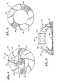
- Figure 3 is a plan view, looking in the direction of fluid flow into the pump, of forward impeller part 16, which is basically composed of an inner hub portion 44 and an outer annular portion 46, the two portions being secured together by means of long vanes 30.
- Short vanes 32 are interposed between long vanes 30 so that vanes 30 and 32 are equispaced about the circumference of upper impeller part 16.
- FIG 4 is a plan view of rear impeller part 18, looking opposite to the direction of fluid flow into the pump, i.e., opposite to the direction of the view of Figure 3.
- Rear impeller part 18 is composed essentially of an annular ring 48 carrying short vanes 34, each of which is aligned with an associated portion of a respective one of vanes 30 or 32.
- each vane 30, 32, 34 is given a curvature such that the variation of the tangent of the blade angle as a function of impeller radius has a positive value along the length of each blade.
- FIGs 3 and 4 additionally illustrate one of the drive plates 28 which is installed between impeller parts 16 and 18 and which are spaced apart around the circumference of the impeller.
- the axial spacing between vanes 30, 32, 34 and housing parts 2 and 4 are of the order of 0.12 inch at the outer diameter of the impeller.
- the surface of rear housing part 4 which delimits chamber 6 has a slight upward slope toward shaft 20 so that the axial spacing between the vanes and that surface of lower housing part 4 exhibits a slight progressive decrease in the direction toward shaft 20.
- Vanes 34 and the portions of vanes 30 which project toward rear housing part 4 act to subject blood which is present between the impeller and rear housing part 4 to a radial outward force, and thereby prevent blood from recirculating around the outer edge of the impeller.
- the action of these vane portions together with the sharp shear edge provided by rear housing part 4 around shaft 20 at the side bordering chamber 6 serve to sweep blood away from the region where shaft 20 passes through rear housing part 4, which is a potential area of stasis, and thus prevent thrombus formation at that location.
- vanes 30, 32, 34 are configured with the goal of minimizing the acceleration and shock experienced by blood within the pump.
- the inlet blade angle of each vane is selected so that, for a selected impeller speed, the velocity produced by each vane closely corresponds to the inlet flow velocity of the blood.
- each vane 30, 32, 34 was determined on the basis of the following equation: where:
- FIG. 5 illustrates the basic components of a magnetic drive according to the present invention.
- This drive is composed of a plurality of permanent magnet units 50 mounted on a plate 52 having a central opening 53 for connection to the shaft of a drive motor.
- One-half of the drive is shown in Figure 5.
- Each magnet unit 50 is composed of two bar magnets 54 each having its magnetic axis oriented parallel to the axis of rotation of plate 52, with the magnets 54 of each unit 50 being oriented in polarity opposition to one another, as shown.
- the magnetic poles of each unit 50 are oriented opposite to those of each adjacent unit 50.
- Each unit 50 is further composed of an arcuate plate 56 of ferromagnetic material completing the magnetic circuit at one end of the associated unit 50.
- the magnetic drive is disposed directly beneath rear housing part 4 so that magnet units 50 surround housing 8 and plate 52 is behind cap 10.
- the end of each magnet unit 50 which is remote from plate 52 faces a respective one of plates 28.
- the spacing between plates 28 and units 50 is made as small as possible in order to minimize the air gap between each plate 28 and its associated unit 50, and thus maximize the magnetic attraction exerted on each plate 28.
- the arrangement of magnetic units 50 is such that the magnetic flux path of each unit is completed through a respective one of plates 28 and the magnetic paths associated with adjacent ones of plates 28 are maintained isolated from each other by the orientations of the magnets associated with adjacent units 50.
- the magnetic attraction forces exerted on plates 28 cause impeller 16, 18 to rotate in unison therewith.
- the drive arrangement shown in Figure 5 produces particularly strong magnetic forces, making possible the use of thin, unmagnetized plates 28 and permitting a sufficient drive force to be imparted to impeller 16, 18 even with a comparatively large air gap between units 50 and plates 28.
Priority Applications (1)
| Application Number | Priority Date | Filing Date | Title |
|---|---|---|---|
| DE1990629149 DE69029149T2 (de) | 1990-04-09 | 1990-04-09 | Zentrifugalblutpumpe und Motorantrieb |
Applications Claiming Priority (4)
| Application Number | Priority Date | Filing Date | Title |
|---|---|---|---|
| US07/320,212 US5017103A (en) | 1989-03-06 | 1989-03-06 | Centrifugal blood pump and magnetic coupling |
| EP90303809A EP0451376B1 (de) | 1989-03-06 | 1990-04-09 | Zentrifugalblutpumpe und Motorantrieb |
| HK98106660A HK1007519A1 (en) | 1989-03-06 | 1998-06-25 | Centrifugal blood pump and motor drive |
| HK98106661A HK1007520A1 (en) | 1989-03-06 | 1998-06-25 | Centrifugal blood pump and motor drive |
Related Parent Applications (2)
| Application Number | Title | Priority Date | Filing Date |
|---|---|---|---|
| EP90303809.9 Division | 1990-04-09 | ||
| EP90303809A Division EP0451376B1 (de) | 1989-03-06 | 1990-04-09 | Zentrifugalblutpumpe und Motorantrieb |
Publications (3)
| Publication Number | Publication Date |
|---|---|
| EP0560466A2 true EP0560466A2 (de) | 1993-09-15 |
| EP0560466A3 EP0560466A3 (de) | 1993-10-20 |
| EP0560466B1 EP0560466B1 (de) | 1996-11-13 |
Family
ID=27269912
Family Applications (2)
| Application Number | Title | Priority Date | Filing Date |
|---|---|---|---|
| EP93201562A Expired - Lifetime EP0560466B1 (de) | 1989-03-06 | 1990-04-09 | Zentrifugalblutpumpe und Motorantrieb |
| EP90303809A Expired - Lifetime EP0451376B1 (de) | 1989-03-06 | 1990-04-09 | Zentrifugalblutpumpe und Motorantrieb |
Family Applications After (1)
| Application Number | Title | Priority Date | Filing Date |
|---|---|---|---|
| EP90303809A Expired - Lifetime EP0451376B1 (de) | 1989-03-06 | 1990-04-09 | Zentrifugalblutpumpe und Motorantrieb |
Country Status (3)
| Country | Link |
|---|---|
| US (1) | US5017103A (de) |
| EP (2) | EP0560466B1 (de) |
| HK (1) | HK1007519A1 (de) |
Cited By (3)
| Publication number | Priority date | Publication date | Assignee | Title |
|---|---|---|---|---|
| DE4430853A1 (de) * | 1994-08-31 | 1996-03-07 | Jostra Medizintechnik | Zentrifugal-Blutpumpe |
| WO1997037698A1 (de) * | 1996-04-04 | 1997-10-16 | Rau Guenter | Intravasale blutpumpe |
| WO1998000185A1 (de) * | 1996-06-29 | 1998-01-08 | Rau Guenter | Blutpumpe nach dem rotationspumpenprinzip |
Families Citing this family (74)
| Publication number | Priority date | Publication date | Assignee | Title |
|---|---|---|---|---|
| US5288216A (en) * | 1990-11-23 | 1994-02-22 | U.S. Philips Corporation | Fan unit for generating gas streams |
| US5290236A (en) * | 1991-09-25 | 1994-03-01 | Baxter International Inc. | Low priming volume centrifugal blood pump |
| US5263924A (en) * | 1991-09-25 | 1993-11-23 | Baxter International Inc. | Integrated low priming volume centrifugal pump and membrane oxygenator |
| EP0653022B1 (de) * | 1992-07-30 | 2001-12-05 | Cobe Cardiovascular, Inc. | Kreiselblutpumpe |
| US5405251A (en) * | 1992-09-11 | 1995-04-11 | Sipin; Anatole J. | Oscillating centrifugal pump |
| US5266265A (en) * | 1992-10-08 | 1993-11-30 | Baxter International, Inc. | Modular disposable blood oxygenator/heat exchanger with durable heat source component, selectively including rotary or ventricular blood pump, venous reservoir, and auxiliary heat exchange component |
| EP0599138A3 (de) * | 1992-11-27 | 1994-12-07 | Urawa Kohgyo Co Ltd | Blutpumpe für die Blutzirkulation. |
| US5393207A (en) * | 1993-01-21 | 1995-02-28 | Nimbus, Inc. | Blood pump with disposable rotor assembly |
| DE4321260C1 (de) * | 1993-06-25 | 1995-03-09 | Westphal Dieter Dipl Ing Dipl | Blutpumpe als Zentrifugalpumpe |
| FR2715442B1 (fr) * | 1994-01-26 | 1996-03-01 | Lorraine Carbone | Pompe centrifuge à entraînement magnétique. |
| WO1999015212A1 (en) * | 1997-09-24 | 1999-04-01 | The Cleveland Clinic Foundation | Flow controlled blood pump system |
| US5840070A (en) | 1996-02-20 | 1998-11-24 | Kriton Medical, Inc. | Sealless rotary blood pump |
| US5695471A (en) * | 1996-02-20 | 1997-12-09 | Kriton Medical, Inc. | Sealless rotary blood pump with passive magnetic radial bearings and blood immersed axial bearings |
| US6302661B1 (en) | 1996-05-03 | 2001-10-16 | Pratap S. Khanwilkar | Electromagnetically suspended and rotated centrifugal pumping apparatus and method |
| JP2000510929A (ja) * | 1996-05-03 | 2000-08-22 | ユニバーシティ・オブ・ユタ | 磁力で懸垂且つ回転されるハイブリッド型遠心圧送装置及び方法 |
| US6074180A (en) * | 1996-05-03 | 2000-06-13 | Medquest Products, Inc. | Hybrid magnetically suspended and rotated centrifugal pumping apparatus and method |
| US5685698A (en) * | 1996-07-30 | 1997-11-11 | Smoll; Owen Clark | Method and apparatus for a pulsatile blood pump with no hemolysis |
| US6071093A (en) * | 1996-10-18 | 2000-06-06 | Abiomed, Inc. | Bearingless blood pump and electronic drive system |
| US5890883A (en) * | 1997-03-19 | 1999-04-06 | The Cleveland Clinic Foundation | Rotodynamic pump with non-circular hydrodynamic bearing journal |
| AUPO902797A0 (en) * | 1997-09-05 | 1997-10-02 | Cortronix Pty Ltd | A rotary blood pump with hydrodynamically suspended impeller |
| EP0900572B1 (de) * | 1997-09-04 | 2005-01-12 | Levitronix LLC | Zentrifugalpumpe |
| US6250880B1 (en) * | 1997-09-05 | 2001-06-26 | Ventrassist Pty. Ltd | Rotary pump with exclusively hydrodynamically suspended impeller |
| US5951267A (en) * | 1997-09-24 | 1999-09-14 | Ingersoll-Dresser Pump Co. | Diaphragm for seal-less integral-motor pump |
| US6120537A (en) * | 1997-12-23 | 2000-09-19 | Kriton Medical, Inc. | Sealless blood pump with means for avoiding thrombus formation |
| JPH11244376A (ja) * | 1998-02-27 | 1999-09-14 | Kyocera Corp | 血液ポンプ |
| CA2330048C (en) * | 1998-04-22 | 2004-04-20 | University Of Utah | Implantable centrifugal blood pump with hybrid magnetic bearings |
| GB2337795A (en) * | 1998-05-27 | 1999-12-01 | Ebara Corp | An impeller with splitter blades |
| DE29821565U1 (de) * | 1998-12-02 | 2000-06-15 | Impella Cardiotech Ag | Lagerlose Blutpumpe |
| US6234772B1 (en) | 1999-04-28 | 2001-05-22 | Kriton Medical, Inc. | Rotary blood pump |
| US7022100B1 (en) | 1999-09-03 | 2006-04-04 | A-Med Systems, Inc. | Guidable intravascular blood pump and related methods |
| US6672409B1 (en) | 2000-10-24 | 2004-01-06 | The Charles Machine Works, Inc. | Downhole generator for horizontal directional drilling |
| US6773670B2 (en) | 2001-02-09 | 2004-08-10 | Cardiovention, Inc. C/O The Brenner Group, Inc. | Blood filter having a sensor for active gas removal and methods of use |
| US6730267B2 (en) * | 2001-02-09 | 2004-05-04 | Cardiovention, Inc. | Integrated blood handling system having active gas removal system and methods of use |
| US6824358B2 (en) * | 2002-11-13 | 2004-11-30 | Jms Co., Ltd. | Turbo blood pump |
| US7022099B2 (en) * | 2003-03-17 | 2006-04-04 | Cardiovention, Inc. | Extracorporeal blood handling system with automatic flow control and methods of use |
| DE10336902C5 (de) | 2003-08-08 | 2019-04-25 | Abiomed Europe Gmbh | Intrakardiale Pumpvorrichtung |
| JP2007085269A (ja) * | 2005-09-22 | 2007-04-05 | Fuji Koki Corp | 排水ポンプ |
| US8657875B2 (en) * | 2005-09-26 | 2014-02-25 | Abiomed, Inc. | Method and apparatus for pumping blood |
| US8672611B2 (en) | 2006-01-13 | 2014-03-18 | Heartware, Inc. | Stabilizing drive for contactless rotary blood pump impeller |
| JP5155186B2 (ja) | 2006-01-13 | 2013-02-27 | ハートウェア、インコーポレイテッド | 回転式血液ポンプ |
| GB0623326D0 (en) * | 2006-11-22 | 2007-01-03 | British Engines Ltd | Metal stem seal |
| US8489190B2 (en) | 2007-10-08 | 2013-07-16 | Ais Gmbh Aachen Innovative Solutions | Catheter device |
| US8439859B2 (en) | 2007-10-08 | 2013-05-14 | Ais Gmbh Aachen Innovative Solutions | Catheter device |
| EP2194278A1 (de) | 2008-12-05 | 2010-06-09 | ECP Entwicklungsgesellschaft mbH | Fluidpumpe mit einem rotor |
| US8366418B2 (en) * | 2009-06-12 | 2013-02-05 | Gulfstream, Inc. | Magnetic centrifugal pump |
| EP2273124B1 (de) * | 2009-07-06 | 2015-02-25 | Levitronix GmbH | Zentrifugalpumpe und Verfahren zum Ausgleichen des axialen Schubs in einer Zentrifugalpumpe |
| US8690749B1 (en) | 2009-11-02 | 2014-04-08 | Anthony Nunez | Wireless compressible heart pump |
| US9555174B2 (en) | 2010-02-17 | 2017-01-31 | Flow Forward Medical, Inc. | Blood pump systems and methods |
| CN103495219B (zh) | 2010-02-17 | 2017-08-08 | 弗洛福沃德医药股份有限公司 | 用来增大静脉总直径的系统和方法 |
| US9662431B2 (en) | 2010-02-17 | 2017-05-30 | Flow Forward Medical, Inc. | Blood pump systems and methods |
| MX2010002024A (es) * | 2010-02-22 | 2011-08-30 | Amc Medicion Y Control S A De C V | Micro generador de energia electrica, acoplado magneticamente. |
| EP2388029A1 (de) | 2010-05-17 | 2011-11-23 | ECP Entwicklungsgesellschaft mbH | Pumpenanordnung |
| EP2399639A1 (de) | 2010-06-25 | 2011-12-28 | ECP Entwicklungsgesellschaft mbH | System zum einführen einer pumpe |
| EP2407186A1 (de) | 2010-07-15 | 2012-01-18 | ECP Entwicklungsgesellschaft mbH | Rotor für eine Pumpe, hergestellt mit einem ersten, elastischen Werkstoff |
| US9227001B2 (en) | 2010-10-07 | 2016-01-05 | Everheart Systems Inc. | High efficiency blood pump |
| RU2754302C2 (ru) | 2011-08-17 | 2021-08-31 | Артио Медикал, Инк. | Системы кровяных насосов и способы |
| CN104185485B (zh) | 2011-08-17 | 2017-07-04 | 弗洛福沃德医药股份有限公司 | 增加静脉和动脉的总直径的系统和方法 |
| EP2606919A1 (de) | 2011-12-22 | 2013-06-26 | ECP Entwicklungsgesellschaft mbH | Schleuseneinrichtung zum Einführen eines Katheters |
| EP2606920A1 (de) | 2011-12-22 | 2013-06-26 | ECP Entwicklungsgesellschaft mbH | Schleuseneinrichtung zum Einführen eines Katheters |
| US9211369B2 (en) * | 2012-06-13 | 2015-12-15 | Ension, Inc | Compact integrated blood pump oxygenator or gas transfer device with hydrogel impeller packing material and rollover impeller outlet |
| US10258730B2 (en) | 2012-08-17 | 2019-04-16 | Flow Forward Medical, Inc. | Blood pump systems and methods |
| EP2745869A1 (de) | 2012-12-21 | 2014-06-25 | ECP Entwicklungsgesellschaft mbH | Schleusenanordnung für die Einführung eines strangförmigen Körpers, insbesondere eines Katheters, in einen Patientenkörper |
| US10294944B2 (en) | 2013-03-08 | 2019-05-21 | Everheart Systems Inc. | Flow thru mechanical blood pump bearings |
| US9057353B2 (en) * | 2013-03-15 | 2015-06-16 | Michael S. Aubuchon, Sr. | Shaft-less radial vane turbine generator |
| TWI725016B (zh) * | 2015-03-20 | 2021-04-21 | 日商荏原製作所股份有限公司 | 用於離心式泵浦之葉輪 |
| EP3448487A4 (de) | 2016-04-29 | 2020-04-29 | Flow Forward Medical, Inc. | Leitungsspitzen und systeme und verfahren zur verwendung |
| CN107115573A (zh) * | 2017-05-09 | 2017-09-01 | 李国荣 | 单支点离心泵心脏辅助装置 |
| CN107519549A (zh) * | 2017-09-30 | 2017-12-29 | 清华大学天津高端装备研究院 | 一种新型单自由度磁悬浮离心式叶轮 |
| CN108785770A (zh) * | 2018-04-18 | 2018-11-13 | 清华大学天津高端装备研究院 | 一种能够减少溶血的体外血泵 |
| EP3826695A4 (de) | 2018-07-24 | 2022-04-20 | CardiacAssist, Inc. | Rotationsblutpumpe |
| CN112689716B (zh) * | 2018-10-18 | 2023-06-30 | 波士顿科学国际有限公司 | 血泵轴轴承 |
| US20200306434A1 (en) * | 2019-03-25 | 2020-10-01 | Boston Scientific Scimed Inc. | Mechanical circulatory support pump drive with corrosion protection |
| WO2022081101A1 (en) | 2020-10-12 | 2022-04-21 | Koc Universitesi | Implantable centrifugal cardiac assist pump having permanent magnets embedded in impeller |
| CN113090535B (zh) * | 2021-04-25 | 2022-09-27 | 中国科学院上海应用物理研究所 | 一种高温介质泵抗颗粒渣浆水力装置 |
Citations (4)
| Publication number | Priority date | Publication date | Assignee | Title |
|---|---|---|---|---|
| GB1059440A (en) * | 1965-03-30 | 1967-02-22 | Rortron Mfg Company Inc | Bearing assembly |
| USRE28742E (en) * | 1967-10-26 | 1976-03-23 | Pumps capable of use as heart pumps | |
| GB2083953A (en) * | 1980-08-27 | 1982-03-31 | Ferranti Ltd | Air turbine generators for missiles |
| US4643641A (en) * | 1984-09-10 | 1987-02-17 | Mici Limited Partnership Iv | Method and apparatus for sterilization of a centrifugal pump |
Family Cites Families (41)
| Publication number | Priority date | Publication date | Assignee | Title |
|---|---|---|---|---|
| US28742A (en) * | 1860-06-19 | Machine foe | ||
| US851457A (en) * | 1906-08-02 | 1907-04-23 | John Verner | Centrifugal fan. |
| US1225805A (en) * | 1914-01-24 | 1917-05-15 | Turbo Company | Air and gas compressor. |
| US1880911A (en) * | 1928-11-03 | 1932-10-04 | Jr Augustus C Durdin | Seal for shaft bearings |
| US2028360A (en) * | 1933-06-19 | 1936-01-21 | Logan Gear Company | Pump |
| US2157597A (en) * | 1936-03-29 | 1939-05-09 | Jr Samuel F Dupree | Means for sealing shafts |
| US2154199A (en) * | 1936-06-01 | 1939-04-11 | Thompson Prod Inc | Sealing construction |
| US2207371A (en) * | 1938-03-02 | 1940-07-09 | Gen Motors Corp | Fluid sealing device |
| US2243227A (en) * | 1938-07-19 | 1941-05-27 | Alfred S Marlow | Shaft sealing means |
| US2231690A (en) * | 1938-07-25 | 1941-02-11 | Ford Motor Co | Fluid pump seal |
| US2471753A (en) * | 1946-07-12 | 1949-05-31 | Johnston George | Pump device |
| US2481172A (en) * | 1948-05-17 | 1949-09-06 | Jesse D Staggs | Magnetically driven fluidhandling device |
| US2540968A (en) * | 1948-12-23 | 1951-02-06 | Hamilton Thomas Corp | Bearing structure for pump shafts |
| US2669668A (en) * | 1949-02-05 | 1954-02-16 | Hermag Pumps Ltd | Magnetically driven centrifugal pump |
| US2810349A (en) * | 1954-07-19 | 1957-10-22 | Tormag Transmissions Ltd | Direct coupled magnetic drive centrifugal pumps |
| DE1051123B (de) * | 1955-11-09 | 1959-02-19 | Paul Bungartz | Kreiselpumpe bzw. Kreiselverdichter ohne Wellendurchtrittsoeffnung |
| BE553207A (de) * | 1955-12-08 | |||
| US3074347A (en) * | 1958-11-21 | 1963-01-22 | Tokheim Corp | Electric drive unit and mounting |
| US3299819A (en) * | 1964-12-07 | 1967-01-24 | Flo Mac Inc | Magnetic drive |
| FR1570882A (de) * | 1967-06-22 | 1969-06-13 | ||
| US3487784A (en) * | 1967-10-26 | 1970-01-06 | Edson Howard Rafferty | Pumps capable of use as heart pumps |
| US3957389A (en) * | 1967-10-26 | 1976-05-18 | Bio-Medicus, Inc. | Pumping apparatus and process characterized by gentle operation |
| US4037984A (en) * | 1967-10-26 | 1977-07-26 | Bio-Medicus, Inc. | Pumping apparatus and process characterized by gentle operation |
| US3970408A (en) * | 1967-10-26 | 1976-07-20 | Bio-Medicus, Inc. | Apparatus for use with delicate fluids |
| US3541607A (en) * | 1968-05-29 | 1970-11-17 | Itt | Centrifugal pump |
| US3608088A (en) * | 1969-04-17 | 1971-09-28 | Univ Minnesota | Implantable blood pump |
| US3647324A (en) * | 1969-12-18 | 1972-03-07 | Edson Howard Rafferty | Electrically driven pumps capable of use as heart pumps |
| JPS525002Y2 (de) * | 1973-09-29 | 1977-02-02 | ||
| US3867655A (en) * | 1973-11-21 | 1975-02-18 | Entropy Ltd | Shaftless energy conversion device |
| US4065234A (en) * | 1975-12-22 | 1977-12-27 | Nihon Kagaku Kizai Kabushiki Kaisha | Magnetically driven rotary pumps |
| DE2624058C2 (de) * | 1976-05-28 | 1984-11-15 | Franz Klaus-Union, 4630 Bochum | Permanentmagnetpumpe |
| US4135253A (en) * | 1976-11-30 | 1979-01-23 | Medtronic, Inc. | Centrifugal blood pump for cardiac assist |
| US4253798A (en) * | 1978-08-08 | 1981-03-03 | Eiichi Sugiura | Centrifugal pump |
| US4304532A (en) * | 1979-12-17 | 1981-12-08 | Mccoy Lee A | Pump having magnetic drive |
| US4688998A (en) * | 1981-03-18 | 1987-08-25 | Olsen Don B | Magnetically suspended and rotated impellor pump apparatus and method |
| US4589822A (en) * | 1984-07-09 | 1986-05-20 | Mici Limited Partnership Iv | Centrifugal blood pump with impeller |
| US4606698A (en) * | 1984-07-09 | 1986-08-19 | Mici Limited Partnership Iv | Centrifugal blood pump with tapered shaft seal |
| US4678409A (en) * | 1984-11-22 | 1987-07-07 | Fuji Photo Film Co., Ltd. | Multiple magnetic pump system |
| US4645432A (en) * | 1986-02-14 | 1987-02-24 | General Motors Corporation | Magnetic drive vehicle coolant pump |
| US4844707A (en) * | 1987-06-12 | 1989-07-04 | Kletschka Harold D | Rotary pump |
| US4898518A (en) * | 1988-08-31 | 1990-02-06 | Minnesota Mining & Manufacturing Company | Shaft driven disposable centrifugal pump |
-
1989
- 1989-03-06 US US07/320,212 patent/US5017103A/en not_active Expired - Fee Related
-
1990
- 1990-04-09 EP EP93201562A patent/EP0560466B1/de not_active Expired - Lifetime
- 1990-04-09 EP EP90303809A patent/EP0451376B1/de not_active Expired - Lifetime
-
1998
- 1998-06-25 HK HK98106660A patent/HK1007519A1/xx not_active IP Right Cessation
Patent Citations (4)
| Publication number | Priority date | Publication date | Assignee | Title |
|---|---|---|---|---|
| GB1059440A (en) * | 1965-03-30 | 1967-02-22 | Rortron Mfg Company Inc | Bearing assembly |
| USRE28742E (en) * | 1967-10-26 | 1976-03-23 | Pumps capable of use as heart pumps | |
| GB2083953A (en) * | 1980-08-27 | 1982-03-31 | Ferranti Ltd | Air turbine generators for missiles |
| US4643641A (en) * | 1984-09-10 | 1987-02-17 | Mici Limited Partnership Iv | Method and apparatus for sterilization of a centrifugal pump |
Non-Patent Citations (1)
| Title |
|---|
| US-E-28742, please read US-E-RE28742 * |
Cited By (3)
| Publication number | Priority date | Publication date | Assignee | Title |
|---|---|---|---|---|
| DE4430853A1 (de) * | 1994-08-31 | 1996-03-07 | Jostra Medizintechnik | Zentrifugal-Blutpumpe |
| WO1997037698A1 (de) * | 1996-04-04 | 1997-10-16 | Rau Guenter | Intravasale blutpumpe |
| WO1998000185A1 (de) * | 1996-06-29 | 1998-01-08 | Rau Guenter | Blutpumpe nach dem rotationspumpenprinzip |
Also Published As
| Publication number | Publication date |
|---|---|
| US5017103A (en) | 1991-05-21 |
| EP0560466A3 (de) | 1993-10-20 |
| HK1007519A1 (en) | 1999-04-16 |
| EP0560466B1 (de) | 1996-11-13 |
| EP0451376A1 (de) | 1991-10-16 |
| EP0451376B1 (de) | 1996-06-19 |
Similar Documents
| Publication | Publication Date | Title |
|---|---|---|
| EP0560466A2 (de) | Zentrifugalblutpumpe und Motorantrieb | |
| US3877844A (en) | Pump | |
| JP4018342B2 (ja) | 軸受不使用血液ポンプ | |
| EP0810374B1 (de) | Kreiselpumpenaggregat | |
| US4927337A (en) | Magnetically driven pump | |
| JP2989233B2 (ja) | ターボ形ポンプ | |
| US6171078B1 (en) | Centrifugal pump | |
| JP3207858B2 (ja) | 無シールロトダイナミックポンプ | |
| US4717315A (en) | Small size axial-flow molecular pump using a magnetic bearing | |
| US4606698A (en) | Centrifugal blood pump with tapered shaft seal | |
| US3803432A (en) | Bearing structure for mounting rotors in motors having spherical air gaps and including means for limiting axial movement of the rotors | |
| EP1186310B1 (de) | Turboblutpumpe | |
| US4295803A (en) | Separating machine | |
| JP4340183B2 (ja) | 遠心式血液ポンプ装置 | |
| CA2215527A1 (en) | Pump with co-axial magnetic coupling | |
| US4043706A (en) | Bearing support structure for electro-magnet driven pump | |
| US4615662A (en) | Axial thrust compensation for centrifugal pump | |
| JP2848415B2 (ja) | 遠心血液ポンプ | |
| EP0039435A1 (de) | Schwimmender Dichtring für Zentrifugalpumpe | |
| CN110573742A (zh) | 磁性接合的泵 | |
| EP0120179A1 (de) | Laufrad mit nur einer Schaufel für eine Zentrifugalpumpe | |
| CA2014078C (en) | Centrifugal blood pump and motor drive | |
| CN1061836A (zh) | 一体化的离心泵和电机 | |
| US3846050A (en) | Centrifugal pumps having rotatable pole rings supported in contactless bearings | |
| EP0287924B1 (de) | Drehfasspumpe |
Legal Events
| Date | Code | Title | Description |
|---|---|---|---|
| PUAI | Public reference made under article 153(3) epc to a published international application that has entered the european phase |
Free format text: ORIGINAL CODE: 0009012 |
|
| PUAL | Search report despatched |
Free format text: ORIGINAL CODE: 0009013 |
|
| 17P | Request for examination filed |
Effective date: 19930615 |
|
| AC | Divisional application: reference to earlier application |
Ref document number: 451376 Country of ref document: EP |
|
| AK | Designated contracting states |
Kind code of ref document: A2 Designated state(s): BE CH DE FR GB LI NL |
|
| AK | Designated contracting states |
Kind code of ref document: A3 Designated state(s): BE CH DE FR GB LI NL |
|
| RIN1 | Information on inventor provided before grant (corrected) |
Inventor name: DAHL, TERRANCE JAY |
|
| 17Q | First examination report despatched |
Effective date: 19941115 |
|
| GRAG | Despatch of communication of intention to grant |
Free format text: ORIGINAL CODE: EPIDOS AGRA |
|
| GRAH | Despatch of communication of intention to grant a patent |
Free format text: ORIGINAL CODE: EPIDOS IGRA |
|
| GRAH | Despatch of communication of intention to grant a patent |
Free format text: ORIGINAL CODE: EPIDOS IGRA |
|
| GRAA | (expected) grant |
Free format text: ORIGINAL CODE: 0009210 |
|
| AC | Divisional application: reference to earlier application |
Ref document number: 451376 Country of ref document: EP |
|
| AK | Designated contracting states |
Kind code of ref document: B1 Designated state(s): BE CH DE FR GB LI NL |
|
| REF | Corresponds to: |
Ref document number: 69029149 Country of ref document: DE Date of ref document: 19961219 |
|
| RAP2 | Party data changed (patent owner data changed or rights of a patent transferred) |
Owner name: C.R. BARD, INC. |
|
| REG | Reference to a national code |
Ref country code: CH Ref legal event code: NV Representative=s name: RITSCHER & SEIFERT PATENTANWAELTE VSP |
|
| NLT2 | Nl: modifications (of names), taken from the european patent patent bulletin |
Owner name: C.R. BARD, INC. |
|
| ET | Fr: translation filed | ||
| PLBE | No opposition filed within time limit |
Free format text: ORIGINAL CODE: 0009261 |
|
| STAA | Information on the status of an ep patent application or granted ep patent |
Free format text: STATUS: NO OPPOSITION FILED WITHIN TIME LIMIT |
|
| 26N | No opposition filed | ||
| PGFP | Annual fee paid to national office [announced via postgrant information from national office to epo] |
Ref country code: GB Payment date: 20000405 Year of fee payment: 11 |
|
| PGFP | Annual fee paid to national office [announced via postgrant information from national office to epo] |
Ref country code: DE Payment date: 20000410 Year of fee payment: 11 |
|
| PGFP | Annual fee paid to national office [announced via postgrant information from national office to epo] |
Ref country code: FR Payment date: 20000411 Year of fee payment: 11 |
|
| PGFP | Annual fee paid to national office [announced via postgrant information from national office to epo] |
Ref country code: CH Payment date: 20000414 Year of fee payment: 11 |
|
| PGFP | Annual fee paid to national office [announced via postgrant information from national office to epo] |
Ref country code: BE Payment date: 20000526 Year of fee payment: 11 |
|
| PGFP | Annual fee paid to national office [announced via postgrant information from national office to epo] |
Ref country code: NL Payment date: 20000530 Year of fee payment: 12 |
|
| NLS | Nl: assignments of ep-patents |
Owner name: LIFESTREAM INTERNATIONAL,INC.;LIFESTREAM INTERNATI |
|
| REG | Reference to a national code |
Ref country code: FR Ref legal event code: TP |
|
| BECA | Be: change of holder's address |
Free format text: 20000426 *LIFESTREAM INTERNATIONAL INC. A TEXAS CORP.:2828 NORTH CRESCENT RIDGE DRIVE, THE WOODLANDS TEXAS 77381 |
|
| BECH | Be: change of holder |
Free format text: 20000426 *LIFESTREAM INTERNATIONAL INC. A TEXAS CORP. |
|
| PG25 | Lapsed in a contracting state [announced via postgrant information from national office to epo] |
Ref country code: GB Free format text: LAPSE BECAUSE OF NON-PAYMENT OF DUE FEES Effective date: 20010409 |
|
| PG25 | Lapsed in a contracting state [announced via postgrant information from national office to epo] |
Ref country code: BE Free format text: LAPSE BECAUSE OF NON-PAYMENT OF DUE FEES Effective date: 20010430 |
|
| PG25 | Lapsed in a contracting state [announced via postgrant information from national office to epo] |
Ref country code: LI Free format text: LAPSE BECAUSE OF NON-PAYMENT OF DUE FEES Effective date: 20010508 Ref country code: CH Free format text: LAPSE BECAUSE OF NON-PAYMENT OF DUE FEES Effective date: 20010508 |
|
| BERE | Be: lapsed |
Owner name: LIFESTREAM INTERNATIONAL INC. A TEXAS CORP. Effective date: 20010430 |
|
| GBPC | Gb: european patent ceased through non-payment of renewal fee |
Effective date: 20010409 |
|
| REG | Reference to a national code |
Ref country code: CH Ref legal event code: PL |
|
| PG25 | Lapsed in a contracting state [announced via postgrant information from national office to epo] |
Ref country code: DE Free format text: LAPSE BECAUSE OF NON-PAYMENT OF DUE FEES Effective date: 20020201 |
|
| PG25 | Lapsed in a contracting state [announced via postgrant information from national office to epo] |
Ref country code: NL Free format text: LAPSE BECAUSE OF NON-PAYMENT OF DUE FEES Effective date: 20021101 |
|
| PG25 | Lapsed in a contracting state [announced via postgrant information from national office to epo] |
Ref country code: FR Free format text: LAPSE BECAUSE OF NON-PAYMENT OF DUE FEES Effective date: 20021231 |
|
| NLV4 | Nl: lapsed or anulled due to non-payment of the annual fee |
Effective date: 20021101 |
|
| REG | Reference to a national code |
Ref country code: FR Ref legal event code: ST |
|
| PG25 | Lapsed in a contracting state [announced via postgrant information from national office to epo] |
Ref country code: FR Free format text: LAPSE BECAUSE OF NON-PAYMENT OF DUE FEES Effective date: 20010430 |