EP0560060B1 - Meterung pump made of plastics for pasty material - Google Patents
Meterung pump made of plastics for pasty material Download PDFInfo
- Publication number
- EP0560060B1 EP0560060B1 EP93101902A EP93101902A EP0560060B1 EP 0560060 B1 EP0560060 B1 EP 0560060B1 EP 93101902 A EP93101902 A EP 93101902A EP 93101902 A EP93101902 A EP 93101902A EP 0560060 B1 EP0560060 B1 EP 0560060B1
- Authority
- EP
- European Patent Office
- Prior art keywords
- wall
- paste
- pump according
- dispensing pump
- housing part
- Prior art date
- Legal status (The legal status is an assumption and is not a legal conclusion. Google has not performed a legal analysis and makes no representation as to the accuracy of the status listed.)
- Expired - Lifetime
Links
Images


Classifications
-
- F—MECHANICAL ENGINEERING; LIGHTING; HEATING; WEAPONS; BLASTING
- F04—POSITIVE - DISPLACEMENT MACHINES FOR LIQUIDS; PUMPS FOR LIQUIDS OR ELASTIC FLUIDS
- F04B—POSITIVE-DISPLACEMENT MACHINES FOR LIQUIDS; PUMPS
- F04B19/00—Machines or pumps having pertinent characteristics not provided for in, or of interest apart from, groups F04B1/00 - F04B17/00
-
- B—PERFORMING OPERATIONS; TRANSPORTING
- B05—SPRAYING OR ATOMISING IN GENERAL; APPLYING FLUENT MATERIALS TO SURFACES, IN GENERAL
- B05B—SPRAYING APPARATUS; ATOMISING APPARATUS; NOZZLES
- B05B11/00—Single-unit hand-held apparatus in which flow of contents is produced by the muscular force of the operator at the moment of use
- B05B11/0005—Components or details
- B05B11/0062—Outlet valves actuated by the pressure of the fluid to be sprayed
- B05B11/0064—Lift valves
- B05B11/0067—Lift valves having a valve seat located downstream the valve element (take precedence)
-
- B—PERFORMING OPERATIONS; TRANSPORTING
- B05—SPRAYING OR ATOMISING IN GENERAL; APPLYING FLUENT MATERIALS TO SURFACES, IN GENERAL
- B05B—SPRAYING APPARATUS; ATOMISING APPARATUS; NOZZLES
- B05B11/00—Single-unit hand-held apparatus in which flow of contents is produced by the muscular force of the operator at the moment of use
- B05B11/01—Single-unit hand-held apparatus in which flow of contents is produced by the muscular force of the operator at the moment of use characterised by the means producing the flow
- B05B11/10—Pump arrangements for transferring the contents from the container to a pump chamber by a sucking effect and forcing the contents out through the dispensing nozzle
- B05B11/1001—Piston pumps
- B05B11/1016—Piston pumps the outlet valve having a valve seat located downstream a movable valve element controlled by a pressure actuated controlling element
-
- B—PERFORMING OPERATIONS; TRANSPORTING
- B05—SPRAYING OR ATOMISING IN GENERAL; APPLYING FLUENT MATERIALS TO SURFACES, IN GENERAL
- B05B—SPRAYING APPARATUS; ATOMISING APPARATUS; NOZZLES
- B05B11/00—Single-unit hand-held apparatus in which flow of contents is produced by the muscular force of the operator at the moment of use
- B05B11/0005—Components or details
- B05B11/0062—Outlet valves actuated by the pressure of the fluid to be sprayed
- B05B11/0072—A valve member forming part of an outlet opening
-
- B—PERFORMING OPERATIONS; TRANSPORTING
- B05—SPRAYING OR ATOMISING IN GENERAL; APPLYING FLUENT MATERIALS TO SURFACES, IN GENERAL
- B05B—SPRAYING APPARATUS; ATOMISING APPARATUS; NOZZLES
- B05B11/00—Single-unit hand-held apparatus in which flow of contents is produced by the muscular force of the operator at the moment of use
- B05B11/01—Single-unit hand-held apparatus in which flow of contents is produced by the muscular force of the operator at the moment of use characterised by the means producing the flow
- B05B11/10—Pump arrangements for transferring the contents from the container to a pump chamber by a sucking effect and forcing the contents out through the dispensing nozzle
- B05B11/1028—Pumps having a pumping chamber with a deformable wall
- B05B11/1035—Pumps having a pumping chamber with a deformable wall the pumping chamber being a bellow
-
- B—PERFORMING OPERATIONS; TRANSPORTING
- B05—SPRAYING OR ATOMISING IN GENERAL; APPLYING FLUENT MATERIALS TO SURFACES, IN GENERAL
- B05B—SPRAYING APPARATUS; ATOMISING APPARATUS; NOZZLES
- B05B11/00—Single-unit hand-held apparatus in which flow of contents is produced by the muscular force of the operator at the moment of use
- B05B11/01—Single-unit hand-held apparatus in which flow of contents is produced by the muscular force of the operator at the moment of use characterised by the means producing the flow
- B05B11/10—Pump arrangements for transferring the contents from the container to a pump chamber by a sucking effect and forcing the contents out through the dispensing nozzle
- B05B11/1028—Pumps having a pumping chamber with a deformable wall
- B05B11/1036—Pumps having a pumping chamber with a deformable wall the outlet valve being opened in the direction opposite to the fluid flow downstream the outlet valve by the pressure acting on a valve controlling element
Definitions
- the invention relates to a metering pump made of plastic for dispensing metered amounts of paste-like substances from a bottle, can or tube-like paste container with a spring-elastic bellows as a pump organ, which connects between a dimensionally stable, upper housing part and a lower, also coaxially and telescopically movable, also dimensionally stable housing part is arranged, its upper end portion sealingly against an annular wall of a radial, provided with at least one paste passage intermediate wall of the upper housing part and its lower end portion sealingly against an annular collar of a radial partition of the lower housing part, and wherein the upper housing part is composed of two hollow bodies and has a closable outlet opening and the lower housing part is provided with a suction valve and is connected or connectable to the paste container.
- a metering pump of the generic type is known for example from DE-Gbm 88 00 880.0.
- the intermediate wall of the upper, telescopic housing part guided in the lower housing part is provided with a pipe socket directed downwards against the partition or the suction valve, which is sealingly enclosed by a reinforced annular collar of the bellows.
- this pipe socket is provided with a conical valve seat ring surface on which a closing member rests, which resiliently rests on the end wall of the upper, two-part housing part and is axially movably guided in the pipe socket by means of an axial cross rib.
- the upper housing part consists of two locking hollow bodies, one of which has a cylindrical guide wall with which it is guided in an axially movable manner in the lower housing part between two limit positions.
- the second hollow body of the upper housing part which is inserted in a protruding cylindrical wall section above the intermediate wall, has an eccentric, channel-like outlet opening which runs parallel to the axis and which is directly connected to a cavity in which the closing element of the dispensing valve is arranged and the rest of it is connected to the interior of the bellows via this dispensing valve, while the upper housing part as a whole moves downward relative to the lower housing part in the course of a delivery stroke.
- Paste dispensers are also already known (US Pat. No. 4,438,871 and DE-OS 30 38 917), in which stopper-like closing elements for the dispensing opening are arranged on elastic membrane walls which are acted upon by the medium to be dispensed during the working stroke in the opening direction.
- these are not metering pumps that have a bellows as a pump organ.
- two manually operable delivery pistons are provided which, in cooperation with suction valves, simultaneously suck in two media from two paste containers located one inside the other and separate and via separate channels into one surrounding the closing element and from the membrane wall carry limited storage space.
- the invention has for its object to provide for a metering pump of the generic type from the least easy to manufacture and assemble individual parts, functionally reliable closing device for the outlet opening in any direction of the upper housing part and at the same time to form a storage space with the smallest possible volume of content.
- a hollow guide body protrudes into the hollow space of the upper housing part provided with the outlet opening and a closing end wall, which lies sealingly on the intermediate wall and which, together with the inner wall of the end wall, lies tightly against or integrally molded, lateral Boundary walls or inner walls delimit a paste stowage space provided with the outlet opening, which is connected to the paste passage of the intermediate wall via at least one paste guide channel, the guide body being provided with a resilient membrane wall opposite the outlet opening, which has a surface area coaxial with the axis of the outlet opening, has plug-like closing member for the outlet opening.
- the invention is described as a metering pump for a paste dispenser for reasons of easier understanding.
- the invention is only suitable for the metered dispensing of paste-like substances. Rather, it can also be used for the metered dispensing of liquid substances, also in connection with an atomizing nozzle.
- the functional, especially the friction-related defects of the proposed metering pump (DE-Pat. Application P 40 35 922.0) cannot occur with this solution according to the invention.
- the diaphragm wall is not subject to static or dynamic sliding friction, nor is it subjected to the return spring force of the bellows or any other return spring.
- a membrane wall as an actuating member for the plug-like closing member has the considerable advantage that it can be integrally formed on another, already existing component and that, apart from its elastic closing force, it is not exposed to any frictional resistances that affect its function, namely opening and Closing the exhaust port could affect.
- the storage space can be designed so that its receiving volume and thus the remaining amount of the medium remaining in it can be kept as small as possible, but on the other hand, the Membrane area, which needs a certain size for a perfect opening and closing, optimal can be designed.
- the embodiment according to claim 2 represents a particularly simple design option, which is particularly advantageous in terms of shape and assembly technology.
- the configuration according to claim 5 contributes in particular to achieving an airtight seal of the cavity in the guide body or in the hollow displacement piston provided according to claim 9, which reduces the residual volume is provided within the bellows.
- the rectangular, preferably square surface shape of the membrane wall provided according to claim 8 results in a considerably improved functionality compared to the usual round shapes, because this gives the membrane wall a higher elasticity with the same diameter of its inner circle.
- the paste dispenser shown as an exemplary embodiment in the drawing has a cylindrical cross-sectional shape.
- the embodiment according to the invention can also be implemented with an oval or other cross-sectional shape.
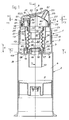
- the paste dispenser shown completely in section in FIG. 1 has a metering pump 1 as the upper part and a paste container 2 as the lower part, which is integrally formed as a cylindrical hollow body on a cylindrical lower housing part 3 and is provided in a known manner with a trailing piston 5.
- the interior 6 of the paste container 2 is separated from the interior 7 of the lower housing part 3 by a radial partition 8, on which a downward-directed cylindrical intake concentric with the common central axis 9 is integrally formed.
- An upper housing part 4 is telescopically guided in the cylindrical outer wall 11 of the lower housing part 3 by means of a likewise cylindrical guide wall 12.
- This housing part 4 is movable by an axial stroke H and is connected to the lower housing part 3 or to its partition 8 by a bellows 13 serving as a pumping element.
- the lower cylindrical end section 14 of the bellows 3 sits sealingly in an upwardly directed annular collar 15 of the dividing wall 8.
- annular shoulder Inside the intake port 10 there is an upwardly directed annular shoulder provided with a central through opening 16 and with a rounded outer lateral surface 17 serving as a valve seat surface 18 on the resilient and sealing via an axial connecting webs seated integrally on the end portion 14 of the bellows 13, cap-like valve closing member 19, which together with the ring extension 18 forms the lower suction valve 20 of the metering pump 1.
- the upper housing part 4 of the metering pump 1 consists of three individual parts, namely the lower hollow body 21 with the cylindrical guide wall 12, an upper hollow body 22 and a hollow guide body 23 projecting into this hollow body 22.
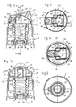
- the lower hollow body 21 is shown as an individual part in FIGS 6 to 9 shown in different views and sectional views.
- the upper hollow body 22 is shown as an individual part in FIGS. 10 to 13 and the guide body 23 in FIGS. 14 to 17.
- the cylindrical guide wall 12 of the lower hollow body 22 is adjoined by a cylindrical outer wall 24 which is somewhat tapered in outer diameter and which forms with the guide wall 12 an outer shoulder 25 serving as a movement stop, which in FIG uppermost rest position of the upper housing part 4 axially abuts an inwardly directed edge rib 26 of the cylindrical outer wall 11 of the housing part 3.
- a radial intermediate wall 27 the outer wall 24 is provided with an inner circumferential locking groove 28, which serves to latch a circumferential locking rib 29 of the upper hollow body 22.
- a cylindrical annular wall piece 30 is integrally formed, which, as can be seen from FIGS.
- a cylindrical annular wall 33 is integrally formed on the intermediate wall 27 within the annular wall socket 30, to which an essentially cylindrical displacement piston 36 adjoins in one piece via a conical section 34, which projects into the interior 35 of the bellows 13 serving as the first pumping chamber and which has a closed end wall 37 has.
- a conical section 34 Arranged in the radial region of the conical section 34 are two approximately diametrically opposite passage channels 38 and 39 which are rectangular in cross section and which are each formed by three axially parallel auxiliary walls 40, 41, 42 or 43, 44, 45 and the annular wall 33.
- a transverse support wall 33 ′ is arranged in the region of the conical section 34 and ends in the plane of the top of the intermediate wall 27.
- a passage opening 47 is arranged between the annular wall 33 and the annular wall socket 30 in the intermediate wall 27, which connects the interior of the annular wall socket 30 with the cylindrical cavity 48 of a cylindrical extension 49, which is provided on its upper end face with a conically rounded valve seat ring 50.
- the upper hollow body 22 of the upper housing part 4 shown as an individual part in FIGS. 10 to 13 above the cylindrical wall section 51 provided with the circumferential locking rib 29 and an annular collar 52 tightly seated on the upper end face 51 of the outer wall 24 of the lower hollow body 21
- Shaped, integrally connected wall sections provided, which are aligned essentially with an oval cross-section outlet opening 53, the axis 54 of which is inclined at an inclination angle ⁇ of approximately 45 ° with respect to the central axis 9.
- the hollow body 22 is formed by a running end wall 55, which also inclines towards the outlet opening 53 limited, which is provided on its outside with transverse gripping ribs 56 and to which laterally fluted wall elements 57 and 58 are connected in a symmetrical arrangement with respect to the axial plane of symmetry 9 '.
- a running end wall 55 which also inclines towards the outlet opening 53 limited, which is provided on its outside with transverse gripping ribs 56 and to which laterally fluted wall elements 57 and 58 are connected in a symmetrical arrangement with respect to the axial plane of symmetry 9 '.
- two axially parallel and parallel to the axial center plane 9' running inner walls 59, 60 are integrally and integrally formed, which are arranged symmetrically to the center plane 9 'and are connected to the inside of the circumferential wall 51' at both ends without gaps.
- These two inner walls 59 and 60 are each stepped in the transverse direction and each have wall sections 61 and 62 with a larger distance a and wall sections 63 and 64 with a smaller distance b and are connected to one another by wall sections 65 and 66 running transversely thereto.
- These inner walls 59 and 60 each extend without gaps from the inside of the end wall 55 to the level of the lower end edge 67 of the wall section 51. It can be seen in particular from FIG. 10 that the transverse wall sections 65 and 66 are not arranged in the vertical central plane 9 ′′ running transverse to the inner walls 59, 60, but in the half opposite the outlet opening 53. The reason is explained in more detail below.
- a plurality of guide ribs 68 running parallel to one another are arranged on the inside of the end wall 55 and form strip channels 69 leading to the discharge opening 53, the purpose of which will be explained in more detail below.
- the hollow guide body 23 shown as an individual part in FIGS. 14 to 17 is constructed on a circular flange disk 71 which has two rectangular openings 72 and 73.
- the diameter of the flange disk 71 is matched to the inside diameter of the section of the outer wall 24 of the lower hollow body 21 above the intermediate wall 27 and is provided with a thickness d such that after the joining of these three individual parts 21, 22 and 23 between the intermediate wall 27 of the lower hollow body 21 and the lower end edge 67 of the upper hollow body 22 is tightly clamped and otherwise rests directly on the upper side of the intermediate wall 27.
- a transverse wall 77 and an arcuate front wall 78, a cover wall 79 and a resilient membrane wall 80 is an open at the bottom Limits cavity 81, which is in the assembled state with the cavity 81 'of the displacer 36 and is filled with air.
- a closing member 82 for the outlet opening 53 is integrally formed, which has the shape of a closed, rounded or slightly conical, plug-like tubular body which has a cross section adapted to the cross-sectional shape of the discharge opening 53 and its axis 83 to the vertical central axis 9 the flange disk 71 has the same angle of inclination ⁇ as the axis 54 of the outlet opening 53 of the hollow body 22. Accordingly, the membrane wall 80 also lies in a plane 83 which is perpendicular to the axis 83 of the closing element 82 or perpendicular to the axis 54 of the outlet opening 53, which is to say that the membrane wall 80 is opposite the outlet opening 53 in parallel.
- This arrangement ensures that the opening and closing movements of the closing element 80 caused by the membrane wall 80 are at least approximately exactly coaxial with the axis 54 of the dispensing opening 53, so that an all-round uniform annular gap is created when opening, which leads to a straight, axial paste outlet in Guaranteed shape of a paste strand.
- the guide ribs 68 in the mouth region of the outlet opening 53 are designed as guide elements for the plug-like or peg-like closing element 82.
- the side walls 75 and 76 of the guide body 23 are similar to the inner walls 59, 60 of the hollow body 22 gradually offset in the transverse direction, so that they also have wall sections 84 and 85 (Fig. 3 and 4), the outer sides of which are spaced a and thus sealing can rest on the inner sides of the inner wall sections 61 and 62 of the hollow body 22, and wall sections 86 and 87, the outer sides of which have the spacing b from one another and lie sealingly against the inner wall sections 63 and 64 if these parts are assembled in a functional manner to form the upper housing part 4.
- the height of the top wall 79 of the guide body 23 is arranged such that it has a certain axial distance from the inside 55 'of the end wall 55 of the upper hollow body 22 or from the guide ribs 68 arranged thereon and thus forms a flat connecting channel 92 which forms the upper mouth openings connect the paste guide channels 90 and 91 to the paste storage space 93 which surrounds the closing element 82 and tapers towards the outlet opening 53.
- the cover wall 79 of the guide body 23 runs parallel to the inclined end wall 55 of the upper hollow body 22.
- the transverse wall 77 of the guide body is supported on the auxiliary wall 33 '.
- the membrane wall 80 is arranged over the two side wall sections 84 and 85 which are at a greater distance a from one another, whereby the advantage is achieved that given the spatial conditions which, on the one hand, are aimed at a paste storage space 93 that is as small as possible, a maximum size and at the same time a rectangular or at least approximately square and thus optimal surface shape of the membrane wall 80 is achieved.
- a rectangular, square shape in particular a considerable improvement in membrane elasticity with the same material and approximately the same side length or approximately the same diameter.
- This second storage space 93/1 is separated from the connecting channel 92 by a transverse wall section 94 which projects upward from the cover wall 79 and which bears against the underside of the guide ribs 68 of the end wall 55 of the hollow body 22;
- a transverse wall section 94 which projects upward from the cover wall 79 and which bears against the underside of the guide ribs 68 of the end wall 55 of the hollow body 22;
- the transverse wall section 94 can also be raised up to the inside 55 'of the end wall 55, so that it lies tightly there. In this case, this transverse wall section 94 is split or several to provide slot-like openings which only connect the strip channels 69 to the second storage space 93/1.
- valve seat ring 50 of the cylindrical projection 49 is provided with a resiliently seated, cap-like valve closing element 95, which is connected in one piece to the guide body 23 or with its flange disk 71 via a plurality of essentially vertical connecting webs 96 'and axially resilient on the valve seat ring 50 sits on. Together with the valve seat ring 50, this valve closing element 95 forms an additional outlet valve 96, through which the second storage space 93/1 is connected to the second pumping chamber 32 via the cavity 48.
- the second pump chamber 32 which concentrically surrounds the bellows 13, is connected by a radial opening 97, which is arranged in the lower section of the annular wall socket 31 of the housing part 2, to a second suction channel 98 arranged eccentrically outside the annular collar 15.
- This intake duct 98 opens into the annular space 99 surrounding the intake connector 10, in which the second medium, which may have a different color, is located.
- valve-like closing or for the formation of a second suction valve 100 on the circumference of the lower, cylindrical end section 14 of the bellows 13 an elastic ring lip 101 is formed, which prevents the medium from flowing back from the second pumping chamber 32 into the suction channel 98, but which allows the second medium to flow through the suction channel 98 and the opening 97 into the second pumping chamber 32 during the suction stroke of the upper housing part 4 .
- FIGS. 1a and 2a another embodiment of the upper part of the metering pump 1 is shown, which differs from that of FIGS. 1 and 2 in that the intermediate wall 27 of the lower hollow body 21 of the upper housing part 4 is not with a displacement piston 36 but is only provided with the annular wall 33 and with two passages 38 'and 39', which instead of the passage channels 38 and 39 establish the connection between the interior 35 of the bellows 13 and the paste guide channels 90 and 91, respectively.
- the metering pump according to the invention which was explained in more detail above with the aid of a paste dispenser, can in principle also be used for liquid media. To do this, however, it is necessary to simultaneously output a second medium, i.e. to dispense with the conveyance of a second medium through the second pump chamber 32 and to completely seal the second storage space 93/1 with respect to the connecting channel 92 and the paste storage space 93.
- the guide ribs 68 are then of course no longer required.
- the second intake duct 98 and expediently the intake manifold 10 are also to be dispensed with.
- passage channels 38, 39 or the passages 38 ', 39' and the paste guide channels 90, 91 aligned therewith lie within the radial region of the annular wall 33 and thus within the bellows cross-section, because this results in the paste storage space 93 or the second storage space 93/1 can be made relatively narrow and small in volume.
- the operation of the above-described metering pump 1 differs from the generic, conventional metering pumps, which also have a bellows as a pumping element, essentially in that the closing element of the exhaust valve moves during the working stroke against the direction of exit of the medium and not in the closing direction and that through the closing member 82 immediately closes the outlet opening, so that the paste storage space 93 is hermetically closed in the idle state.
- the opening movement of the plug-like closing element 82 is generated by the hydraulic overpressure in the paste storage space 93 which arises during the downward working stroke of the upper housing part 4 and which results in a corresponding opening movement of the membrane wall 80 and thus of the closing element 82 towards the inside.
- the closing element 82 is moved back into the closing position by the spring forces which are inherent in the membrane wall 80 and supported by the air compression in the cavity of the guide body 23 and possibly the displacement piston 36, so that a tight closure the outlet opening is created.
- the mechanical function test when dry ie without the presence of the medium in the dosing pump 1, can be done in a simple manner by measuring the occurrence of a sufficiently large vacuum by a vacuum gauge attached to the intake manifold 10 during the intake stroke of the upper housing part, that is to say during its return to the rest position.
- a vacuum gauge attached to the intake manifold 10 during the intake stroke of the upper housing part, that is to say during its return to the rest position.
- the inner walls 59, 60 of the upper hollow body 22 of the upper housing part 2 could be replaced by correspondingly arranged wall elements which are integrally formed directly on the guide body 23. The edge edges of such wall elements would then preferably be sealed in internal sealing grooves or on internal sealing strips of the upper hollow body 22.
Description
Die Erfindung betrifft eine Dosierpumpe aus Kunststoff zur Abgabe dosierter Mengen pastenartiger Stoffe aus einem flaschen, dosen- oder tubenartigen Pastenbehälter mit einem federelastischen Faltenbalg als Pumporgan, der verbindend zwischen einem formstabilem, oberen Gehäuseteil und einem unteren, dazu koaxialen und teleskopartig beweglichen, ebenfalls formstabilem Gehäuseteil angeordnet ist, wobei sein oberer Endabschnitt dichtend an einer Ringwand einer radialen, mit wenigstens einem Pastendurchlaß versehenen Zwischenwand des oberen Gehäuseteils und sein unterer Endabschnitt dichtend an einem Ringbund einer radialen Trennwand des unteren Gehäuseteils anliegt, und wobei das obere Gehäuseteil aus zwei Hohlkörpern zusammengesetzt ist und eine verschließbare Auslaßöffnung aufweist und das untere Gehäuseteil mit einem Ansaugventil versehen und mit dem Pastenbehälter verbunden oder verbindbar ist.The invention relates to a metering pump made of plastic for dispensing metered amounts of paste-like substances from a bottle, can or tube-like paste container with a spring-elastic bellows as a pump organ, which connects between a dimensionally stable, upper housing part and a lower, also coaxially and telescopically movable, also dimensionally stable housing part is arranged, its upper end portion sealingly against an annular wall of a radial, provided with at least one paste passage intermediate wall of the upper housing part and its lower end portion sealingly against an annular collar of a radial partition of the lower housing part, and wherein the upper housing part is composed of two hollow bodies and has a closable outlet opening and the lower housing part is provided with a suction valve and is connected or connectable to the paste container.
Eine Dosierpumpe der gattungsgemäßen Art ist beispielsweise aus dem DE-Gbm 88 00 880.0 bekannt. Dort ist die Zwischenwand des oberen, teleskopartigen im unteren Gehäuseteil geführten Gehäuseteils mit einem nach unten gegen die Trennwand bzw. das Ansaugventil gerichteten Rohrstutzen versehen, der von einem verstärkten Ringbund des Faltenbalgs dichtend umschlossen ist. Auf seiner Oberseite ist dieser Rohrstutzen mit einer konischen Ventilsitz-Ringfläche versehen, auf welcher ein Schließorgan federnd aufsitz, welches sich an der abschließenden Stirnwand des oberen, zweiteiligen Gehäuseteils federnd abstützt und mittels einer axialen Kreuzrippe im Rohrstutzen axial beweglich geführt ist. Auch hier besteht das obere Gehäuseteil aus zwei rastend miteinander verbundenen Hohlkörpern, von denen der eine eine zylindrische Führungswand aufweist, mit welcher er im unteren Gehäuseteil axial beweglich zwischen zwei Grenzpositionen geführt ist. Der zweite Hohlkörper des oberen Gehäuseteils, der oberhalb der Zwischenwand in einen überstehenden zylindrischen Wandungsabschnitt rastend eingesetzt ist, weist eine exzentrische, kanalartige Auslaßöffnung auf, die achsparallel verläuft und die unmittelbar mit einem Hohlraum in Verbindung steht, in dem das Schließorgan des Ausgabeventils angeordnet ist und der im übrigen über dieses Ausgabeventil mit dem Innenraum des Faltenbalgs verbunden ist, während sich das obere Gehäuseteil insgesamt relativ zum unteren Gehäuseteil in Ausübung eines Förderhubes nach unten bewegt.A metering pump of the generic type is known for example from DE-Gbm 88 00 880.0. There, the intermediate wall of the upper, telescopic housing part guided in the lower housing part is provided with a pipe socket directed downwards against the partition or the suction valve, which is sealingly enclosed by a reinforced annular collar of the bellows. On its top, this pipe socket is provided with a conical valve seat ring surface on which a closing member rests, which resiliently rests on the end wall of the upper, two-part housing part and is axially movably guided in the pipe socket by means of an axial cross rib. Here, too, the upper housing part consists of two locking hollow bodies, one of which has a cylindrical guide wall with which it is guided in an axially movable manner in the lower housing part between two limit positions. The second hollow body of the upper housing part, which is inserted in a protruding cylindrical wall section above the intermediate wall, has an eccentric, channel-like outlet opening which runs parallel to the axis and which is directly connected to a cavity in which the closing element of the dispensing valve is arranged and the rest of it is connected to the interior of the bellows via this dispensing valve, while the upper housing part as a whole moves downward relative to the lower housing part in the course of a delivery stroke.
Bei dieser Art von Dosierpumpen, der beispielsweise auch die Dosierpumpe der EP-A-0 194 417 entspricht, und die als Pumporgan einen Faltenbalg aufweisen, sind in der Praxis selbsttätige Verschließeinrichtungen für die Auslaßöffnung des beweglichen Gehäuseteils nicht vorgesehen.In this type of metering pumps, which for example also corresponds to the metering pump of EP-A-0 194 417 and which have a bellows as the pumping element, automatic closing devices for the outlet opening of the movable housing part are not provided in practice.
Es ist jedoch bereits auch eine Dosierpumpe mit einer automatischen Schließeinrichtung für die Auslaßöffnung des oberen Gehäuseteils vorgeschlagen worden (DE-Pat.-Anmeldung P 40 35 922.0), bei welcher im oberen Gehäuseteil ein axial beweglicher Hubkolben angeordnet ist, der mit dem stöpselartigen Schließorgan für die achsparallele Auslaßöffnung versehen ist und der durch das während des Arbeitshubs aus dem Faltenbalg in Richtung Ausgabeöffnung strömende Medium oberseitig beaufschlagt wird, so daß er sich entgegen der Rückstellwirkung des Faltenbalgs oder einer Rückstellfeder unter gleichzeitigem Öffen der Auslaßöffnung nach unten bewegen soll. Der Hubkolben muß während des gegen den Faltenbalg gerichteten Arbeitshubs der Gehäusebewegung vorauseilen. Es hat sich jedoch gezeigt, daß derartige Dosierpumpen aufgrund der ungünstigen Druck- und Reibungsverhältnisse in der Praxis nicht zufriedenstellend arbeiten. Vor allem weil zur Überwindung der statischen Reibung zwischen dem Hubkolben und der Zylinderwand, an welcher er dicht anliegend geführt ist, eine wesentlich größere Hubkraft benötigt wird als danach, wenn der Hubkolben bereits in Bewegung gekommen ist, ist der Öffnungsvorgang stark unterschiedlich und unzuverlässig.However, a metering pump with an automatic closing device for the outlet opening of the upper housing part has already been proposed (DE-Pat.
Es sind auch bereits Pastenspender bekannt (US-PS 4 438 871 und DE-OS 30 38 917), bei denen stöpselartige Schließorgane für die Ausgabeöffnung an elastischen Membranwänden angeordnet sind, die während des Arbeitshubes von dem auszugebenden Medium in Öffnungsrichtung beaufschlagt werden. Dabei handelt es sich jedoch nicht um Dosierpumpen, die als Pumporgan einen Faltenbalg aufweisen. Vielmehr sind bei dem einen bekannten Pastenspender (US-PS 4 438 871) zwei manuell betätigbare Förderkolben vorgesehen, die im Zusammenwirken mit Ansaugventilen gleichzeitig zwei Medien aus zwei ineinander liegenden jedoch getrennten Pastenbehältern ansaugen und über separate Kanäle in einen das Schließorgan umgebenden und von der Membranwand begrenzten Stauraum befördern.
Bei dem anderen Pastenspender (DE-OS 30 38 917) ist ein stabförmiges Schließelement an einer sog. Rollmembrane befestigt und in einem konischen Stauraum angeordnet, der über einen mit einem Innengewinde versehenen Rohrstutzen, der auf einen Gewindehals einer verformbaren Verschlußkappe aufgeschraubt ist, mit einem Pastenbehälter in Verbindung steht. Der Ausgabedruck wird bei dieser Pumpe durch die axiale Verformung der Verschlußkappenwandung, bzw. durch deren Abwärtsbewegung in Achsrichtung bewirkt, wobei der Behälter mit einem Nachlaufkolben versehen ist, der bei der jeweiligen Rückstellbewegung der Verschlußkappe nachläuft.Paste dispensers are also already known (US Pat. No. 4,438,871 and DE-OS 30 38 917), in which stopper-like closing elements for the dispensing opening are arranged on elastic membrane walls which are acted upon by the medium to be dispensed during the working stroke in the opening direction. However, these are not metering pumps that have a bellows as a pump organ. Rather, in one known paste dispenser (US Pat. No. 4,438,871) two manually operable delivery pistons are provided which, in cooperation with suction valves, simultaneously suck in two media from two paste containers located one inside the other and separate and via separate channels into one surrounding the closing element and from the membrane wall carry limited storage space.
In the other paste dispenser (DE-OS 30 38 917) is a rod-shaped closing element on a so-called rolling membrane attached and arranged in a conical storage space, which is connected to a paste container via an internally threaded pipe socket which is screwed onto a threaded neck of a deformable closure cap. The output pressure in this pump is caused by the axial deformation of the closure cap wall or by its downward movement in the axial direction, the container being provided with a trailing piston which runs on during the respective return movement of the closure cap.
Der Erfindung liegt die Aufgabe zugrunde, für eine Dosierpumpe der gattungsgemäßen Art eine aus möglichst wenig einfach herstellbaren und montierbaren Einzelteilen bestehende, funktionssichere Verschließeinrichtung für die in beliebiger Richtung verlaufende Auslaßöffnung des oberen Gehäuseteils zu schaffen und zugleich einen Stauraum mit möglichst geringem Inhaltsvolumen zu bilden.The invention has for its object to provide for a metering pump of the generic type from the least easy to manufacture and assemble individual parts, functionally reliable closing device for the outlet opening in any direction of the upper housing part and at the same time to form a storage space with the smallest possible volume of content.
Gelöst wird diese Aufgabe dadurch, daß in den oberhalb der Zwischenwand liegenden Hohlraum des mit der Auslaßöffnung und einer abschließenden Stirnwand versehenen Hohlkörpers des oberen Gehäuseteils ein hohler Leitkörper hineinragt, der dichtend auf der Zwischenwand aufliegt und der gemeinsam mit an der Innenseite der Stirnwand dicht anliegenden oder einstückig angeformten, seitlichen Begrenzungswänden bzw. Innenwänden einen mit der Auslaßöffnung versehenen Pastenstauraum begrenzt, welcher über wenigstens einen Pastenleitkanal mit dem Pastendurchlaß der Zwischenwand verbunden ist, wobei der Leitkörper mit einer der Auslaßöffnung gegenüberliegenden, federnden Membranwand versehen ist, die in ihrer Flächenmitte ein zur Achse der Auslaßöffnung koaxiales, stöpselartiges Schließorgan für die Auslaßöffnung aufweist.
In den Patentansprüchen ist die Erfindung aus Gründen der leichteren Verständlichkeit als Dosierpumpe für einen Pastenspender beschrieben. Das soll aber nicht einschränkend bedeuten, daß die Erfindung nur zur dosierten Ausgabe von pastenartigen Stoffen geeignet ist. Vielmehr läßt sie sich auch zur dosierten Ausgabe von flüssigen Stoffen, auch in Verbindung mit einer Zerstäuberdüse verwenden. Die funktionellen, besonders die reibungsbedingten Mängel der vorgeschlagenen Dosierpumpe (DE-Pat.-Anmeldung P 40 35 922.0) können bei dieser erfindungsgemäßen Lösung nicht auftreten. Die Membranwand unterliegt weder einer statischen noch einer dynamischen Gleitreibung, und sie ist auch nicht der Rückstellfederkraft des Faltenbalgs oder einer anderen Rückstellfeder ausgesetzt.This object is achieved in that a hollow guide body protrudes into the hollow space of the upper housing part provided with the outlet opening and a closing end wall, which lies sealingly on the intermediate wall and which, together with the inner wall of the end wall, lies tightly against or integrally molded, lateral Boundary walls or inner walls delimit a paste stowage space provided with the outlet opening, which is connected to the paste passage of the intermediate wall via at least one paste guide channel, the guide body being provided with a resilient membrane wall opposite the outlet opening, which has a surface area coaxial with the axis of the outlet opening, has plug-like closing member for the outlet opening.
In the claims, the invention is described as a metering pump for a paste dispenser for reasons of easier understanding. However, this is not intended to mean that the invention is only suitable for the metered dispensing of paste-like substances. Rather, it can also be used for the metered dispensing of liquid substances, also in connection with an atomizing nozzle. The functional, especially the friction-related defects of the proposed metering pump (DE-Pat.
Während bei der vorgeschlagenen Dosierpumpe, bei welcher das stöpselartige Schließorgan für die Auslaßöffnung an einem axial beweglichen Hubkolben befestigt ist, nur eine achsparallele Bewegung des Schließorgans in Frage kommt, besteht bei der erfindungsgemäßen Lösung der bedeutende Vorteil, daß die Membranwand mit dem daran angeformten Schließorgan prinzipiell beliebig angeordnet sein kann. Das bedeutet, daß die Auslaßöffnung, zu deren Achse sich das Schließorgan koaxial bewegen sollte, damit ein gerader Austritt des Pastenstranges gewährleistet ist, zwischen einer radialen Achsrichtung und einer achsparallelen Achsrichtung jede beliebige Zwischenposition einnehmen kann. Außerdem hat die Verwendung einer Membranwand als Betätigungsorgan für das stöpselartige Schließorgan den erheblichen Vorteil, daß es einstückig an einem anderen, ohnehin vorhandenen Bauteil angeformt sein kann und daß es außer seiner elastischen Schließkraft, keinerlei Reibungswiderständen ausgesetzt ist, die seine Funktion, nämlich das Öffenen und Schließen der Auslaßöffnung beeinträchtigen könnte.While in the proposed metering pump, in which the plug-like closing element for the outlet opening is attached to an axially movable reciprocating piston, only one axis-parallel movement of the closing element comes into question, there is the significant advantage in the solution according to the invention that the membrane wall with the closing element formed thereon can in principle be arranged as desired. This means that the outlet opening, to the axis of which the closing element should move coaxially, so that a straight exit of the paste strand is ensured, can assume any intermediate position between a radial axis direction and an axis-parallel axis direction. In addition, the use of a membrane wall as an actuating member for the plug-like closing member has the considerable advantage that it can be integrally formed on another, already existing component and that, apart from its elastic closing force, it is not exposed to any frictional resistances that affect its function, namely opening and Closing the exhaust port could affect.
Ein weiterer bedeutender Vorteil der erfindungsgemäßen Lösung besteht darin, daß durch eine entsprechende Anordnung der Begrenzungswände im Hohlraum des Hohlkörpers der Stauraum so ausgebildet sein kann, daß sein Aufnahmevolumen und somit die Restmenge des in ihm verbleibenden Mediums möglichst klein gehalten werden kann, daß aber andererseits die Membranfläche, die für ein einwandfreies Öffnen und Schließen eine bestimmte Größe benötigt, optimal gestaltet werden kann.
Schließlich ist auch sichergestellt, daß sich die drei Einzelteile, aus denen das obere Gehäuseteil zusammengesetzt ist, sich einfach, d.h. automatisch zusammenfügen lassen, wobei ein weiterer vorteilhafter Gesichtspunkt in der Möglichkeit zu sehen ist, sowohl die Pumpfunktion des Faltenbalgs als auch die Schließ- und Öffnungsfunktion des Schließorgans der Auslaßöffnung trocken, d.h. ohne das Medium, für dessen Ausgabe die Dosierpumpe geschaffen ist, auf dem Montageautomaten maschinell und zudem praktisch kostenlos zu prüfen.Another significant advantage of the solution according to the invention is that by a corresponding arrangement of the boundary walls in the cavity of the hollow body, the storage space can be designed so that its receiving volume and thus the remaining amount of the medium remaining in it can be kept as small as possible, but on the other hand, the Membrane area, which needs a certain size for a perfect opening and closing, optimal can be designed.
Finally, it is also ensured that the three individual parts from which the upper housing part is composed can be simply, ie automatically put together, a further advantageous aspect being seen in the possibility of both the pumping function of the bellows and the closing and Opening function of the closing member of the outlet opening dry, ie without the medium, for the dispensing of which the metering pump is created, to be checked mechanically and also practically free of charge on the automatic assembly machine.
Dabei stellt die Ausgestaltung nach Anspruch 2 eine besonders einfache Gestaltungsmöglichkeit dar, die insbesondere formtechnisch und auch montagetechnisch von Vorteil ist.The embodiment according to
Während sich durch die Ausgestaltungen nach Anspruch 3 und 4 weitere formtechnische und montagetechnische Vorteile ergeben, trägt die Ausgestaltung nach Anspruch 5 insbesondere zur Erzielung einer luftdichten Abdichtung des Hohlraums im Leitkörper bzw. in dem nach Anspruch 9 vorgesehenen hohlen Verdrängerkolben bei, welcher zur Verminderung des Restvolumens innerhalb des Faltenbalgs vorgesehen ist.While there are further advantages in terms of shape and assembly technology as a result of the configurations according to
Die nach Anspruch 6 vorgesehene Anordnung der vom Faltenbalg zum Patenstauraum führenden Verbindungen erlaubt es, daß der Pastenstauraum auf einen nur relativ schmalen Bereich des im oberen Hohlkörper vorhandenen Hohlraums beschränkt werden kann.The arrangement provided according to
Durch die Ausgestaltung nach Anspruch 7 ist es in vorteilhafter Weise möglich, bei kleinsten Raumverhältnissen die größtmöglichste Membranfläche, die eine sichere Funktionsweise garantiert, zu erzielen.Due to the configuration according to
Die gemäß Anspruch 8 vorgesehene rechteckige, vorzugsweise quadratische Flächenform der Membranwand ergibt gegenüber den üblichen runden Formen eine erheblich verbesserte Funktionsweise, weil dadurch die Membranwand bei gleichem Durchmesser seines Innekreises eine höhere Elastizität erhält.The rectangular, preferably square surface shape of the membrane wall provided according to claim 8 results in a considerably improved functionality compared to the usual round shapes, because this gives the membrane wall a higher elasticity with the same diameter of its inner circle.
Auch durch die gemäß Anspruch 10 vorgesehene Führung des Schließorgans kann die Funktionssicherheit wesentlich verbessert werden, und zwar insbesondere hinsichtlich der Bildung eines gleichmäßigen, gerade aus der Auslaßöffnung austretenden Pastenstrangs sowie auch hinsichtlich der erzielung eines luftdichten Verschließens der Auslaßöffnung.
Durch die Ausgestaltungen nach den Ansprüchen 8 bis 15 ist die Möglichkeit geschaffen, dem durch den Faltenbalg, durch die Pastenleitkanäle und den Stauraum hindurch zur Ausgabeöffnung gelangenden Medium, das beispielsweise aus einer weißen Zahnpasta besteht, ein zweites Medium in kleineren Mengen, z. B. in Streifenform beizugeben, wobei der Faltenbalg auch als Pumporgan für das zweite Medium wirksam ist und überdies keine zusätzlichen Einzelteile für die Beigabe dieses zusätzlichen Mediums benötigt werden. Die wenigen zusätzlich erforderlichen Bauteile sind einstückig an ohnehin vorhandenen Bauteilen angeformt und zwar so, daß sie sich bei der Montage ohne weiteres funktionsgerecht zusammenfügen lassen, so daß teilemäßig keine zusätzlichen Kosten entstehen, wenn man davon absieht, daß die Spritzgußformen für diese etwas komplizierteren Teile etwas teurer werden.Functional reliability can also be significantly improved by the guidance of the closing member provided in accordance with
By the configurations according to
Anhand der Zeichnung wird die Erfindung nachstehend am Beispiel eines Pastenspenders näher erläutert. Es zeigt:
- Fig. 1
- einen kompletten Pastenspender mit einer Dosierpumpe der erfindungsgemäßen Art im Schnitt,
- Fig. 2
- einen Teilschnitt II-II aus Fig. 1,
- Fig. 1a
- eine Variante der erfindungsgemäßen Dosierpumpe im Schnitt,
- Fig.2a
- einen Schnitt IIa/II-a aus Fig. 1a,
- Fig. 3
- einen Schnitt III-III aus Fig. 1,
- Fig. 4
- einen Schnitt IV-IV aus Fig. 1,
- Fig. 5
- einen Schnitt V-V aus Fig. 1,
- Fig. 6
- den unteren Hohlkörper des oberen Gehäuseteils als Einzelteil in axialer Unteransicht,
- Fig. 7
- einen Schnitt VII-VII aus Fig. 6,
- Fig. 8
- einen Schnitt VIII-VIII aus Fig. 6,
- Fig. 9
- die Ansicht IX aus Fig. 7,
- Fig. 10
- den oberen Hohlkörper des oberen Gehäuseteils als Einzelteil in Unteransicht,
- Fig. 11
- den oberen Hohlkörper des oberen Gehäuseteils in Draufsicht,
- Fig. 12
- einen Schnitt XII-XII aus Fig. 11,
- Fig. 13
- einen Schnitt XIII-XIII aus Fig. 11,
- Fig. 14
- den Leitkörper als Einzelteil in axialer Unteransicht,
- Fig. 15
- den Leitkörper in axialer Draufsicht,
- Fig. 16
- einen Schnitt XVI-XVI aus Fig. 15,
- Fig. 17
- einen Schnitt XVII-XVII aus Fig. 15.
- Fig. 1
- a complete paste dispenser with a metering pump of the type according to the invention in section,
- Fig. 2
- 2 shows a partial section II-II from FIG. 1,
- Fig. 1a
- a variant of the metering pump according to the invention in section,
- Fig.2a
- 2 a section IIa / II-a from FIG. 1a,
- Fig. 3
- 2 shows a section III-III from FIG. 1,
- Fig. 4
- 2 shows a section IV-IV from FIG. 1,
- Fig. 5
- 2 shows a section VV from FIG. 1,
- Fig. 6
- the lower hollow body of the upper housing part as a single part in an axial bottom view,
- Fig. 7
- 6 shows a section VII-VII from FIG. 6,
- Fig. 8
- 6 shows a section VIII-VIII from FIG. 6,
- Fig. 9
- the view IX from FIG. 7,
- Fig. 10
- the upper hollow body of the upper housing part as a single part in bottom view,
- Fig. 11
- the upper hollow body of the upper housing part in plan view,
- Fig. 12
- 11 shows a section XII-XII from FIG. 11,
- Fig. 13
- 11 shows a section XIII-XIII from FIG. 11,
- Fig. 14
- the guide body as a single part in an axial bottom view,
- Fig. 15
- the guide body in axial plan view,
- Fig. 16
- 15 shows a section XVI-XVI from FIG. 15,
- Fig. 17
- a section XVII-XVII of Fig. 15th
Der in der Zeichnung als Ausführungsbeispiel dargestellte Pastenspender hat eine zylindrische Querschnittsform. Die erfindungsgemäße Ausführung läßt sich aber ebensogut auch mit einer ovalen oder anderen Querschnittsform realisieren.The paste dispenser shown as an exemplary embodiment in the drawing has a cylindrical cross-sectional shape. However, the embodiment according to the invention can also be implemented with an oval or other cross-sectional shape.
Der in Fig. 1 im Schnitt komplett dargestellte Pastenspender weist als Oberteil eine Dosierpumpe 1 auf und als Unterteil einen Pastenbehälter 2, der als zylindrischer Hohlkörper einstückig an einem zylindrischen unteren Gehäuseteil 3 angeformt und in bekannter Weise mit einem Nachlaufkolben 5 versehen ist. Der Innenraum 6 des Pastenbehälters 2 ist vom Innenraum 7 des unteren Gehäuseteils 3 durch eine radiale Trennwand 8 abgetrennt, an welcher ein nach unten gerichteter zylindrischer und konzentrisch zur gemeinsamen Mittelachse 9 angeordneter Ansaugstutzen 10 einstückig angeformt ist.The paste dispenser shown completely in section in FIG. 1 has a
In der zylindrischen Außenwand 11 des unteren Gehäuseteils 3 ist mittels einer ebenfalls zylindrischen Führungswand 12 ein oberes Gehäuseteil 4 teleskopartig geführt. Dieses Gehäuseteil 4 ist um einen Axialhub H beweglich und durch einen als Pumporgan dienenden Faltenbalg 13 mit dem unteren Gehäuseteil 3 bzw. mit dessen Trennwand 8 verbunden. Dabei sitzt der untere zylindrische Endabschnitt 14 des Faltenbalgs 3 dichtend in einem nach oben gerichteten Ringbund 15 der Trennwand 8. Innerhalb des Ansaugstutzens 10 befindet sich ein mit einer zentralen Durchgangsöffnung 16 und mit einer als Ventilsitzfläche dienenden abgerundeten äußeren Mantelfläche 17 versehener, nach oben gerichteter Ringansatz 18 auf dem federnd und dichtend ein über axiale Verbindungsstege einstückig am Endabschnitt 14 des Faltenbalgs 13 angeformtes, kappenartiges Ventilschließorgan 19 aufsitzt, das zusammen mit dem Ringansatz 18 das untere Ansaugventil 20 der Dosierpumpe 1 bildet.An
Das obere Gehäuseteil 4 der Dosierpumpe 1 besteht aus drei Einzelteilen, nämlich dem unteren Hohlkörper 21 mit der zylindrischen Führungswand 12, einem oberen Hohlkörper 22 und aus einem in diesen Hohlkörper 22 hineinragenden, hohlen Leitkörper 23. Der untere Hohlkörper 21 ist als Einzelteil in den Fig. 6 bis 9 in verschiedenen Ansichten und Schnittdarstellungen dargestellt. Der obere Hohlkörper 22 ist als Einzelteil in den Fig. 10 bis 13 dargestellt und der Leitkörper 23 in den Fig. 14 bis 17.The
Wie am besten aus den Fig. 6 bis 9 ersichtlich ist, schließt sich an die zylindrische Führungswand 12 des unteren Hohlkörpers 22 eine im Außendurchmesser etwas verjüngte zylindrische Außenwand 24 an, die mit der Führungswand 12 einen als Bewegungsanschlag dienenden äußeren Absatz 25 bildet, der in oberster Ruheposition des oberen Gehäuseteils 4 an einer nach innen gerichteten Randrippe 26 der zylindrischen Außenwand 11 des Gehäuseteils 3 axial anliegt. (Fig. 1 bis 2a)
Oberhalb einer radialen Zwischenwand 27 ist die Außenwand 24 mit einer inneren, umlaufenden Rastnut 28 versehen, die zur rastenden Aufnahme einer umlaufenden Rastrippe 29 des oberen Hohlkörpers 22 dient. An der Unterseite der Zwischenwand 27 ist einstückig ein zylindrischer Ringwandstutzen 30 angeformt, der, wie aus den Fig. 1 und 2 ersichtlicht ist, dichtend und teleskopartig einen ebenfalls zylindrischen, nach oben gerichteten Ringwandstutzen 31 aufnimmt, der einstückig an der Trennwand 8 des unteren Gehäuseteils 3 angeformt ist. Dabei sind die Innendurchmesser dieser beiden Ringwandstutzen 30 und 31 so gewählt, daß sie vom Umfang des Faltenbalgs 13 einen gewissen radialen Abstand haben und so gemeinsam mit dem Faltenbalg 13 eine zweite, ringförmige Pumpkammer 32 bilden.As can best be seen from FIGS. 6 to 9, the
Above a radial
Innerhalb des Ringwandstutzens 30 ist an die Zwischenwand 27 eine zylindrische Ringwand 33 angeformt, an welche sich einstückig über einen konischen Abschnitt 34 ein im wesentlich zylindrischer Verdrängerkolben 36 anschließt, der in den als erste Pumpkammer dienenden Innenraum 35 des Faltenbalgs 13 hineinragt und der eine geschlossene Stirnwand 37 aufweist.
Im Radialbereich des konischen Abschnitts 34 sind zwei sich etwa diametral gegenüberliegende, im Querschnitt rechteckförmige Durchlaßkanäle 38 und 39 angeordnet, die von jeweils drei achsparallelen Hilfswänden 40, 41, 42 bzw. 43, 44, 45 und der Ringwand 33 gebildet sind.A cylindrical
Arranged in the radial region of the
Außerdem ist im Bereich des konischen Abschnitts 34 eine quer verlaufende Stützwand 33' angeordnet, die in der Ebene der Oberseite der Zwischenwand 27 endet.In addition, a
In der zwischen den beiden Durchlaßkanälen 38 und 39 verlaufenden axialen Symmetrieebene 9' ist zwischen der Ringwand 33 und dem Ringwandstutzen 30 in der Zwischenwand 27 eine Durchlaßöffnung 47 angeordnet, welche den Innenraum des Ringwandstutzens 30 mit dem zylindrischen Hohlraum 48 eines zylindrischen Ansatzes 49 verbindet, welcher auf seiner oberen Stirnseite mit einem konisch abgerundeten Ventilsitzring 50 versehen ist.In the axial plane of symmetry 9 'running between the two
Der in den Fig. 10 bis 13 als Einzelteil dargestellte obere Hohlkörper 22 des oberen Gehäuseteils 4 ist oberhalb des mit der umlaufenden Rastrippe 29 und einem auf der oberen Stirnfläche 51 der Außenwand 24 des unteren Hohlkörpers 21 dicht aufsitzenden Ringbund 52 versehenen zylindrischen Wandabschnitts 51 mit unterschiedlich geformten, einstückig miteinander verbundenen Wandungsabschnitten versehen, die im wesentlichen auf eine im Querschnitt ovale Auslaßöffnung 53 ausgerichtet sind, deren Achse 54 unter einem Neigungswinkel α von etwa 45° gegenüber der Mittelachse 9 geneigt ist. Stirnseitig ist der Hohlkörper 22 von einer ebenfalls zur Auslaßöffnung 53 hin schräg ansteigenden verlaufenden Stirnwand 55 begrenzt, die auf ihrer Außenseite mit quer verlaufenden Griffrippen 56 versehen ist und an welche sich seitlich hohlkehlenartig verlaufende Wandelemente 57 und 58 in zur axialen Symmetrieebene 9' symmetrischer Anordnung anschließen.
An der Innenseite 55' der Stirnwand 55 sind zwei achsparallele und parallel zur axialen Mittelebene 9' verlaufende Innenwände 59, 60 einstückig und lückenlos angeformt, die symmetrisch zur Mittelebene 9' angeordnet und mit der Innenseite der Umfangswandung 51' beidendig lückenlos verbunden sind.The upper
On the inside 55 'of the
Diese beiden Innenwände 59 und 60 sind jeweils in Querrichtung stufenweise abgesetzt und weisen jeweils Wandabschnitte 61 und 62 mit einem größeren Abstand a und Wandabschnitte 63 und 64 mit einem kleineren Abstand b auf und sind durch quer dazu verlaufende Wandabschnitte 65 bzw. 66 miteinander verbunden. Diese Innenwände 59 und 60 erstrecken sich jeweils lückenlos von der Innenseite der Stirnwand 55 bis zur Ebene der unteren Stirnkante 67 des Wandabschnitts 51.
Es ist insbesondere aus Fig. 10 ersichtlich, daß die quer verlaufenden Wandabschnitte 65 und 66 nicht in der vertikalen, quer zu den Innenwänden 59, 60 verlaufenden Mittelebene 9'' sondern in der der Auslaßöffnung 53 gegenüberliegenden Hälfte angeordnet sind. Der Grund dafür wird nachstehend noch näher erläutert.These two
It can be seen in particular from FIG. 10 that the
In den zwischen den Wandabschnitten 63 und 64 mit dem kleineren Abstand b liegenden Bereich sind an der Innenseite der Stirnwand 55 mehrere parallel zueinander verlaufende Leitrippen 68 angeordnet, die zur Ausgabeöffnung 53 hinführende Streifenkanäle 69 bilden, deren Zweck nachstehend noch näher erläutert wird.In the area lying between the
Der in den Fig. 14 bis 17 als Einzelteil dargestellte hohle Leitkörper 23 ist auf einer kreisrunden Flanschscheibe 71 aufgebaut, die zwei rechteckige Öffnungen 72 und 73 aufweist. Der Durchmesser der Flanschscheibe 71 ist so auf den Innendurchmesser des oberhalb der Zwischenwand 27 liegenden Abschnitts der Außenwand 24 des unteren Hohlkörpers 21 abgestimmt und mit einer solchen Dicke d versehen, daß er nach dem Zusammenfügen dieser drei Einzelteile 21, 22 und 23 zwischen der Zwischenwand 27 des unteren Hohlkörpers 21 und der unteren Stirnkante 67 des oberen Hohlkörpers 22 dichtend eingeklemmt ist und im übrigen auf der Oberseite der Zwischenwand 27 direkt aufliegt. Durch achsparallele, symmetrisch zur vertikalen Mittelebene 9' und parallel zu dieser verlaufende Seitenwände 75 und 76, eine Querwand 77 sowie eine kreisbogenförmig gekrümmte Frontwand 78, eine Deckelwand 79 und eine federelastische Membranwand 80 ist ein unten offener Hohlraum 81 begrenzt, der im montierten Zustand mit dem Hohlraum 81' des Verdrängerkolbens 36 in Verbindung steht und luftgefüllt ist.The
In der Flächenmitte der Membranwand 80 ist ein Schließorgan 82 für die Auslaßöffnung 53 einstückig angeformt, das die Form eines stirnseitig geschlossenen, abgerundeten oder leicht konischen, stöpselartigen Rohrkörpers aufweist, der einen der Querschnittsform der Ausgabeöffnung 53 angepaßten Querschnitt und dessen Achse 83 zur vertikalen Mittelachse 9 der Flanschscheibe 71 den gleichen Neigungswinkel α aufweist, wie die Achse 54 der Auslaßöffnung 53 des Hohlkörpers 22. Dementsprechend liegt auch die Membranwand 80 in einer Ebene 83, die rechtwinklig zur Achse 83 des Schließorgans 82 bzw. rechtwinklig zur Achse 54 der Auslaßöffnung 53 verläuft, womit gesagt sein soll, daß die Membranwand 80 der Auslaßöffnung 53 parallel gegenüberliegt. Durch diese Anordnung ist gewährleistet, daß sich die von der Membranwand 80 verursachten Öffnungs- und Schließbewegungen des Schließorganes 80 zumindest annähernd exakt koaxial zur Achse 54 der Ausgabeöffnung 53 vollziehen, so daß beim Öffnen ein rundum gleichmäßiger Ringspalt entsteht, der einen geraden, axialen Pastenaustritt in Form eines Pastenstrangs gewährleistet.
Zu diesem Zweck sind, wie am besten aus den Fig. 1 und 1a ersichtlich ist, die Leitrippen 68 im Mündungsbereich der Auslaßöffnung 53 als Leitelemente für das stöpsel- oder zapfenartige Schließorgan 82 ausgebildet.In the middle of the surface of the
For this purpose, as best shown in FIGS. 1 and 1a it can be seen that the
Die Seitenwände 75 und 76 des Leitkörpers 23 sind ähnlich wie die Innenwände 59, 60 des Hohlkörpers 22 in Querrichtung stufenweise abgesetzt, so daß sie ebenfalls Wandabschnitte 84 und 85 aufweisen (Fig. 3 und 4), deren Außenseiten den Abstand a aufweisen und somit dichtend an den Innenseiten der Innenwandabschnitte 61 und 62 des Hohlkörpers 22 anliegen können, sowie Wandabschnitte 86 und 87, deren Außenseiten den Abstand b voneinander haben und dichtend an den Innenwandabschnitten 63 und 64 anliegen, wenn diese Teile funktionsgerecht zum oberen Gehäuseteil 4 zusammengesetzt sind. Aus den Fig. 3 und 4 ist auch ersichtlich, daß die die gegeneinander versetzten Wandabschnitte 84 und 86 bzw. 85 und 87 miteinander verbindenden quer verlaufenden Wandabschnitte 88 und 89 so angeordnet sind, daß zwischen den Seitenwänden 75 und 76 des Leitkörpers 23 einerseits und den Innenwänden 59 und 60 andererseits Pastenkanäle 90 und 91 gebildet werden, die mit den Durchlaßöffnungen 72 und 73 der Flanschscheibe 71 fluchten, welche ihrerseits die Verbindung zu den Durchlaßkanälen 38 und 39 des unteren Hohlkörpers 21 und somit zum Innenraum 35 des Faltenbalgs 13 herstellen.The
Höhenmäßig ist die Deckelwand 79 des Leitkörpers 23 so angeordnet, daß sie von der Innenseite 55' der Stirnwand 55 des oberen Hohlkörpers 22 bzw. von den daran angeordneten Leitrippen 68 einen gewissen axialen Abstand hat und somit einen flachen Verbindungskanal 92 bildet, der die oberen Mündungsöffnungen der Pastenleitkanäle 90 und 91 mit dem das Schließorgan 82 umschließenden sich zur Auslaßöffnung 53 hin verjüngenden Pastenstauraum 93 verbinden.The height of the
Es ist aus Fig. 1 und 1a ersichtlich, daß die Deckelwand 79 des Leitkörpers 23 parallel zur schräg verlaufenden Stirnwand 55 des oberen Hohlkörpers 22 verläuft. Aus Fig. 1 ist weiter ersichtlich, daß die Querwand 77 des Leitkörpers stützend auf der Hilfswand 33' aufsitzt.
Aus den Fig. 3 und 4 sowie aus den Fig. 14 bis 16 ist auch ersichtlich, daß die Membranwand 80 über den beiden den größeren Abstand a voneinander aufweisenden Seitenwandabschnitten 84 und 85 angeordnet ist, wodurch der Vorteil erreicht wird, daß bei den gegebenen Raumverhältnissen die einerseits auf einen möglichst kleinen Pastenstauraum 93 ausgerichtet sind, eine maximale Größe und zugleich eine reckeckige bzw. zumindest annähernd quadratische und somit optimale Flächenorm der Membranwand 80 erreicht wird. Gegenüber der üblichen, kreisrunden Membranform ergibt eine rechteckige, insbesondere quadratische Flächenform eine erhebliche Verbesserung der Membranelastizität bei gleichem Stoff und etwa gleicher Seitenlänge bzw. etwa gleichem Durchmesser.It can be seen from FIGS. 1 and 1a that the
From FIGS. 3 and 4 and from FIGS. 14 to 16 it can also be seen that the
Aus den Fig. 1, 1a, 3 und 4 ist ersichtlich, daß durch die Querwand 77, die die beiden Seitenwandabschnitte 86 und 87 des Leitkörpers mit dem geringeren Abstand b miteinander verbindet und die im montierten Zustand zwischen den beiden Innenwandabschnitten 63 und 64 des oberen Hohlkörpers 22 liegt, ein zweiter Stauraum 93/1 gebildet ist, in den der zylindrische Ansatz 49 mit dem Ventilsitzring 50 des Hohlkörpers 21 hineinragt. Dieser zweite Stauraum 93/1 ist durch einen die Deckelwand 79 nach oben überragenden Querwandabschnitt 94, der an der Unterseite der Leitrippen 68 der Stirnwand 55 des Hohlkörpers 22 anliegt, vom Verbindungskanal 92 getrennt; durch die von den Leitrippen 68 gebildeten Streifenkanäle 69, die zum Stauraum 93/1 hin offen sind, bestehen jedoch mehrere streifenbildende Verbindungen zur Auslaßöffnung 53, so daß die Möglichkeit besteht, ein zweites Medium aus dem Stauraum 93 dem Ausgabestrang des Hauptmediums in Streifenform zuzuführen. Der Querwandabschnitt 94 kann auch bis zur Innenseite 55' der Stirnwand 55 hochgeführt sein, so daß er dort dicht anliegt. In diesem Fall ist dieser Querwandabschnitt 94 mit mehreren spalt- oder schlitzartigen Öffnungen zu versehen, die nur die Streifenkanäle 69 mit dem zweiten Stauraum 93/1 verbinden.1, 1a, 3 and 4 it can be seen that through the
Zu diesem Zweck ist der Ventilsitzring 50 des zylindrischen Ansatzes 49 mit einem federnd aufsitzenden, kappenartigen Ventilschließorgan 95 versehen, welches über mehrere im wesentlichen vertikal verlaufende Verbindungsstege 96' einstückig mit dem Leitkörper 23 bzw. mit dessen Flanschscheibe 71 verbunden ist und axial federnd auf dem Ventilsitzring 50 aufsitzt. Dieses Ventilschließorgan 95 bildet zusammen mit dem Ventilsitzring 50 ein zusätzliches Auslaßventil 96, durch welches der zweite Stauraum 93/1 über den Hohlraum 48 mit der zweiten Pumpkammer 32 in Verbindung steht. Die zweite Pumpkammer 32, die den Faltenbalg 13 konzentrisch umgibt, ist durch eine radiale Öffnung 97, die im unteren Abschnitt des Ringwandstutzens 31 des Gehäuseteils 2 angeordnet ist, mit einem exzentrisch außerhalb des Ringbundes 15 angeordneten zweiten Ansaugkanal 98 verbunden. Dieser Ansaugkanal 98 mündet in den den Ansaugstutzen 10 umgebenden Ringraum 99, in dem sich das zweite, ggf. farblich unterschiedliche Medium befindet. Zweckmäßigerweise ist zum ventilartigen Schließen bzw. zur Bildung eines zweiten Ansaugventils 100 am Umfang des unteren, zylindrischen Endabschnitts 14 des Faltenbalgs 13 eine elastische Ringlippe 101 angeformt, die ein Zurückfließen des Mediums aus der zweiten Pumpkammer 32 in den Ansaugkanal 98 verhindert, die aber ein Nachfließen des zweiten Mediums durch den Ansaugkanal 98 und die Öffnung 97 in die zweite Pumpkammer 32 beim Ansaughub des oberen Gehäuseteils 4 zuläßt.For this purpose, the
Es besteht aber auch die Möglichkeit, auf die Ringlippe 101 zu verzichten. Dazu ist es allerdings erforderlich, den Durchlaßquerschnitt der Öffnung 97 kleiner zu gestalten, als der gesamte Durchlaßquerschnitt, den die Streifenkanäle 69 an der Innenseite 55' der Stirnwand 55 des oberen Hohlkörpers 22 aufweisen, so daß beim abwärts gerichteten Arbeitshub des oberen Gehäuseteils 4 in der zweiten Pumpkammer 32 ein ausreichend großer Staudruck entsteht, der eine Beförderung des zweiten Mediums durch das Auslaßventil 96 und die Streifenkanäle 69 hindurch zur Ausgabeöffnung 53 bewirken kann.However, there is also the possibility of dispensing with the
In den Fig. 1a und 2a ist eine andere Ausführungsform des oberen Teils der Dosierpumpe 1 dargestellt, die sich von derjenigen der Fig. 1 und 2 dadurch unterscheidt, daß die Zwischenwand 27 des unteren Hohlkörpers 21 des oberen Gehäuseteils 4 nicht mit einem Verdrängerkolben 36 sondern lediglich mit der Ringwand 33 und mit zwei Durchlässen 38' und 39' versehen ist, die anstelle der Durchlaßkanäle 38 und 39 die Verbindung zwischen dem Innenraum 35 des Faltenbalgs 13 und den Pastenleitkanälen 90 bzw. 91 herstellen.1a and 2a, another embodiment of the upper part of the
Es sei noch erwähnt, daß die erfindungsgemäße Dosierpumpe, die vorstehend anhand eines Pastenspenders näher erläutert wurde, prinzipiell auch für flüssige Medien einsetzbar ist. Dazu ist es allerdings erforderlich, auf die gleichzeitige Ausgabe eines zweiten Mediums, d.h. auf das Befördern eines zweiten Mediums durch die zweite Pumpkammer 32 zu verzichten und den zweiten Stauraum 93/1 gegenüber dem Verbindungskanal 92 und dem Pastenstauraum 93 vollständig abzudichten. Die Leitrippen 68 sind dann natürlich auch nicht mehr erforderlich. Ebenso ist auf den zweiten Ansaugkanal 98 und zweckmäßigerweise auch auf den Ansaugstutzen 10 zu verzichten.It should also be mentioned that the metering pump according to the invention, which was explained in more detail above with the aid of a paste dispenser, can in principle also be used for liquid media. To do this, however, it is necessary to simultaneously output a second medium, i.e. to dispense with the conveyance of a second medium through the
Bei beiden Ausführungsformen ist von bedeutendem Vorteil, daß die Durchlaßkanäle 38, 39 bzw. die Durchlässe 38', 39' und mit diesen fluchtenden Pastenleitkanäle 90, 91 innerhalb des Radialbereichs der Ringwand 33 und somit innerhalb des Faltenbalgquerschnitts liegen, weil sich dadurch der Pastenstauraum 93 bzw. auch der zweite Stauraum 93/1 relativ schmal und volumenmäßig klein gestalten läßt.In both embodiments, it is of significant advantage that the
Die Funktionsweise der vorstehend beschriebenen Dosierpumpe 1 unterscheidet sich von den gattungsgemäßen, herkömmlichen Dosierpumpen, die ebenfalls als Pumporgan einen Faltenbalg aufweisen, im wesentlichen dadurch, daß das Schließorgan des Auslaßventiles sich während des Arbeitshubes entgegen der Austrittsrichtung des Mediums bewegt und nicht in Schließrichtung und daß durch das Schließorgan 82 unmittelbar die Auslaßöffnung verschlossen wird, so daß der Pastenstauraum 93 im Ruhezustand luftdicht verschlossen ist. Die Öffnungsbewegung des stöpselartigen Schließorgans 82 wird dabei durch den während des nach unten gerichteten Arbeitshubes des oberen Gehäuseteils 4 entstehenden hydraulischen Überdruck im Pastenstauraum 93 erzeugt, der eine entsprechende Öffnungsbewegung der Membranwand 80 und damit des Schließorgans 82 nach innen zur Folge hat. Sobald dieser Überdruck am unteren Totpunkt der Hubbewegung entfällt, wird das Schließorgan 82 durch die Federkräfte, die der Membranwand 80 innewohnen, und unterstützt durch die Luftkompression im Hohlraum des Leitkörpers 23 und ggf. des Verdrängungskolbens 36 wieder in Schließposition zurückbewegt, so daß ein dichtes Verschließen der Auslaßöffnung entsteht.The operation of the above-described
Die maschinelle Funktionsprüfung im trockenen Zustand, d.h. ohne das Vorhandensein des Mediums in der Dosierpumpe 1, kann in einfacher Weise dadurch erfolgen, daß durch ein an den Ansaugstutzen 10 angesetztes Unterdruckmeßgerät während des Ansaughubes des oberen Gehäuseteils, also während dessen Rückkehr in die Ruhestellung das Entstehen eines ausreichend großen Unterdrucks gemessen wird. Eine solche Funktionprüfung verursacht keine zusätzlichen Kosten; durch sie kann aber die größtmögliche Funktionssicherheit beim praktischen Einsatz garantiert werden.The mechanical function test when dry, ie without the presence of the medium in the
Es sei noch erwähnt, daß auch die Möglichkeit besteht, auf die Innenwände 59, 60 des oberen Hohlkörpers 22 des oberen Gehäuseteils 2 zu verzichten und statt dessen die Seitenwände 75, 76 des Leitkörpers 23 so zu gestalten, daß sie vollkommen dicht an den Innenseiten des oberen Hohlkörpers 22 anliegen und daß sie zugleich die Pastenleitkanäle 90, 91 bilden. Dabei könnten die Innenwände 59, 60 des oberen Hohlkörpers 22 durch räumlich entsprechend angeordnete, einstückig unmittelbar am Leitkörper 23 angeformte Wandelemente ersetzt werden. Die Randkanten solcher Wandelemente wären dann vorzugsweise in inwendigen Dichtungsnuten oder an inwendigen Dichtungsleisten des oberen Hohlkörpers 22 dichtend aufzunehmen.It should also be mentioned that it is also possible to dispense with the
Claims (18)
- A pump for dispensing synthetic plastics material, for delivering quantitively measured quantities of pasty substances from a bottle, can or tube-like paste container (2) with a resiliently flexible corrugated bellows (13) as a pumping means connectively disposed between a form-stable upper housing part (4) and, coaxial therewith and adapted for telescopic movement, a lower and likewise form-stable housing part (3), its upper end portion bearing in sealing-tight manner on an annular wall (33) of a radial intermediate wall (27) of the upper housing part (4) which is provided with at least one paste passage while its bottom end portion bears in sealing-tight manner on an annular collar (15) of a radial separating wall (8) of the bottom housing part (3) and whereby the upper housing part (4) is composed of two hollow members (21, 22) and comprises an occludable outlet orifice (53) and the bottom housing part (3) is provided with an intake valve (20) and is or may be connected to the paste container (2),
characterised in that
in the cavity in the hollow body (22) of the upper housing part (4) which is provided with the outlet orifice (53) and an occluding end wall (55) there projects a hollow conductive member (23) which bears in sealing-tight manner on the intermediate wall (27) and which jointly with lateral limiting walls or inner walls (59, 60) which are integrally formed or bear in sealing-tight manner on the inside face (55') of the end wall (55) a paste stowage space (93) provided with the outlet orifice (53) and which is connected by at least one paste conducting passage (91) to the paste orifice (38, 39, 38', 39') in the intermediate wall (27), whereby the conductive member (23) is provided with a resilient diaphragm wall (80) opposite the outlet orifice (53) and which comprises in the centre of its area and coaxial with the axis (54) of the outlet orifice (53) a stopper-like closure member (82) for the outlet orifice (53). - A dispensing pump according to claim 1, characterised in that the paste stowage space (93) is bounded laterally by two axially parallel inner walls (59, 60) of the hollow body (22) of the upper housing part (4) which is provided with the outlet orifice (53) and the occluding end wall (55) and on which the axially parallel side walls (75, 76) of the guide member (23) bear in sealing-tight manner
- A dispensing pump according to claim 1 or 2, characterised in that the interior walls (59, 60) of the hollow body (22) and the side walls (75, 76) of the conducting body (23) are in each case disposed symmetrically in relation to a central plane (9') in which lie both the axis (54) of the outlet orifice (53) and also the main axis (9) of the two housing parts (3, 4).
- A dispensing pump according to claim 2 or 3, characterised in that the two inner walls (59, 60) of the hollow body (22) and the two side walls (75, 76) of the conductive body (23) have in the transverse direction step-like wall portions (61, 63, 62, 64 or 84, 85, 86, 87) at different distances (a, b) which, by reason of their different lengths, form with the likewise transversely stepwisely graduated side walls (75, 76) of the guide member (23) two substantially diametrically opposite paste guide passages (90, 91).
- A dispensing pump according to one of claims 1 to 4, characterised in that the guide member (23) is provided with a flange disc (71) which rests in sealing-tight manner on the intermediate wall (27) and which has two apertures (72, 73) which connect the through ways (38, 39) or apertures (38', 39') in the intermediate wall (27) to the paste guide passages (90, 91).
- A dispensing pump according to one of claims 1 to 5, characterised in that the apertures (38', 39') or through ways (38, 39) and the paste guide passages (90, 91) lie in a radial area of the intermediate wall (27) or upper hollow body (22) which is no larger than the inside diameter of the annular wall (33).
- A dispensing pump according to one of claims 1 to 6, characterised in that the diaphragm wall (0) is disposed in the region of the side wall portions (84, 85) which is at the greater distance (a).
- A dispensing pump according to claim 7, characterised in that the diaphragm wall (80) has a substantially rectangular flat form in the diagonal centre of which the hollow stopper-like closure member (82) is integrally formed.
- A dispensing pump according to one of claims 1 to 8, characterised in that on the annular wall (34) of the intermediate wall (27) and which is surrounded by the upper end portion of the bellows assembly (13) there is a hollow displacement piston (36) which is open at the top and which projects into the bellows assembly (13) and which comprises two substantially diametrically opposite through ways (38, 39) which are connected in aligned manner with the paste guide passages (90, 91) of the guide member (23).
- A dispensing pump according to one of claims 1 to 9, characterised in that the stopper-like closure member (82) is in the mouth area of the outlet orifice (53) guided at least on its upper side by rib-like guide elements (68).
- A dispensing pump according to claim 1, characterised in that the guide member (23) comprises an axially parallel transverse wall (77) connecting the two side wall portions (86, 87) which are at the smaller distance (b), said transverse wall (77) being disposed radially in the region of or within the annular wall (83) which is enclosed by the upper end portion of the bellows assembly (13) and which form a separate and second stowage space (93/1) together with the two inner wall portions (63, 64) which is at the smaller distance (b) and together with the outer wall portion which is in between.
- A dispensing pump according to one of claims 1 to 11, characterised in that the top wall (79) and the diaphragm wall (80) of the guide member (23) which is adjacent to it are at an axial distance from the end wall (55) of the hollow body (22) by which a connecting passage (92) is formed between the two paste guide passages (90, 91) and the paste stowage space (93) enclosing the closure member (82) of the outlet orifice (53).
- A dispensing pump according to claim 12, characterised in that the second stowage space (93/1) of the upper housing part (4) communicates on the one hand by strip passage and/or by one or more split or slot-like apertures in the transverse wall (77, 94) of the guide member (23) with the connecting passage (92) and on the other by a second outlet valve (96) and, disposed radially outside the bellows assembly (13), an aperture (47) in the intermediate wall (27) is connected to a second pump chamber (32) enclosing the bellows unit (13) and which is connected on the intake side, via an eccentric intake passage (98) in the separating wall (8), to an annular space (99) in the paste container (2) and encloses an intake connector (10).
- A dispensing pump according to claim 13, characterised in that the second pump chamber (32) is constituted by two annular wall connectors (30, 31) which are guided in each in telescopic fashion and which concentrically enclose the bellow assembly (13) at a radial distance being in each case integrally formed on one of the two housing parts (34).
- A dispensing pump according to one of claims 12 to 14, characterised in that in the connecting passage (92) on the inside (55') of the end wall (55) of the upper hollow body (22) there are guide ribs (68) which form strip-like passages (69) which connect the second stowage space (93/1) to the outlet orifice (53).
- A dispensing pump according to one of claims 13 to 15, characterised in that the outlet valve (96) disposed in the second stowage space (93/1) consists of a valve seat ring (50) integrally formed on the intermediate wall (27) and, seated resiliently on the valve seat ring, a valve closure member (95) which is integrally formed on the guide member (23), being connected to it by one or more connecting webs (96').
- A dispensing pump according to claim 13, characterised in that the eccentric intake passage (98) has a smaller throughflow cross-section than the throughflow of the transverse wall (77, 94) by which the second stowage space (93/1) is connected to the first paste stowage chamber (93).
- A dispensing pump according to claim 13, characterised in that like an intake valve, the eccentric intake passage (98) can be occluded in the reflux direction by a closure lip (101) integrally formed on the bellows unit (13) in the same way as a one-way or non-return valve.
Applications Claiming Priority (2)
| Application Number | Priority Date | Filing Date | Title |
|---|---|---|---|
| DE4207800A DE4207800C1 (en) | 1992-03-12 | 1992-03-12 | |
| DE4207800 | 1992-03-12 |
Publications (2)
| Publication Number | Publication Date |
|---|---|
| EP0560060A1 EP0560060A1 (en) | 1993-09-15 |
| EP0560060B1 true EP0560060B1 (en) | 1994-12-28 |
Family
ID=6453830
Family Applications (1)
| Application Number | Title | Priority Date | Filing Date |
|---|---|---|---|
| EP93101902A Expired - Lifetime EP0560060B1 (en) | 1992-03-12 | 1993-02-08 | Meterung pump made of plastics for pasty material |
Country Status (4)
| Country | Link |
|---|---|
| EP (1) | EP0560060B1 (en) |
| JP (1) | JP3373244B2 (en) |
| KR (1) | KR930020017A (en) |
| DE (1) | DE4207800C1 (en) |
Families Citing this family (17)
| Publication number | Priority date | Publication date | Assignee | Title |
|---|---|---|---|---|
| DE4212413C2 (en) * | 1992-04-14 | 1996-09-12 | Andris Raimund Gmbh & Co Kg | Dosing pump made of plastic for highly viscous, especially paste-like media |
| US5476195A (en) * | 1994-10-06 | 1995-12-19 | Procter & Gamble Company | Pump device with collapsible pump chamber and including dunnage means |
| DE4441263A1 (en) * | 1994-11-19 | 1996-05-23 | Caideil M P Teoranta Tormakead | Discharge device for media |
| DE29506682U1 (en) * | 1995-04-19 | 1995-06-29 | Megaplast Dosiersysteme Gmbh | Dispensing pump made of plastic for pasty materials |
| DE29514644U1 (en) * | 1995-09-12 | 1996-02-01 | Piepenstock Friedhelm | Helical compression spring |
| DE19606701A1 (en) * | 1996-02-22 | 1997-08-28 | Caideil M P Teoranta Tourmakea | Discharge device for media |
| DE19606702A1 (en) * | 1996-02-22 | 1997-08-28 | Caideil M P Teoranta Tourmakea | Discharge device for media |
| DE19606703A1 (en) * | 1996-02-22 | 1997-08-28 | Caideil M P Teoranta Tourmakea | Discharge device for media |
| DE19608839A1 (en) * | 1996-03-07 | 1997-09-11 | Ahrens Hans Joachim | Dispenser for adhesive or paint |
| DE19723134A1 (en) * | 1997-06-03 | 1998-12-10 | Pfeiffer Erich Gmbh & Co Kg | Discharge device for media |
| DE19738245C2 (en) * | 1997-09-02 | 1999-10-14 | Goldwell Gmbh | Use of a packaging for dispensing a flowable cosmetic product |
| JP4020249B2 (en) * | 2002-09-27 | 2007-12-12 | 大成化工株式会社 | Spray pump inspection device and inspection method |
| DE20304731U1 (en) * | 2003-03-25 | 2003-06-26 | Megaplast Gmbh & Co Kg | Dosing pump made of plastic |
| DE102007013723A1 (en) * | 2006-12-06 | 2008-06-12 | Megaplast Gmbh & Co. Kg | Hand-operated dispenser for pasty to fluid masses and docking container therefor |
| DE102015104288A1 (en) * | 2015-03-23 | 2016-09-29 | Megaplast Gmbh | Dispenser for dispensing liquid to pasty masses |
| EP3427840B1 (en) * | 2017-07-13 | 2020-12-02 | Aptar Radolfzell GmbH | Liquid dispenser |
| CN111874436A (en) * | 2020-08-18 | 2020-11-03 | 广州尚功塑胶有限公司 | Full plastic pump |
Family Cites Families (11)
| Publication number | Priority date | Publication date | Assignee | Title |
|---|---|---|---|---|
| IT1087232B (en) * | 1977-11-17 | 1985-06-04 | Coster Tecnologie Speciali Spa | MANUALLY CONTROLLED DISPENSING PUMP FOR LIQUID CONTAINERS |
| DE3038917A1 (en) * | 1980-10-15 | 1982-05-27 | Roder, Gottfried, 2400 Lübeck | Compressible paste bottle sealing device - has boss on membrane pulled out of outlet by internal pressure |
| FR2494603A1 (en) * | 1980-11-26 | 1982-05-28 | Normos Norbert | Manually-operated fluid-sprayer - has chamber with elastic wall and rigid tube from nozzle to discharge passage |
| DE3121075A1 (en) * | 1981-05-27 | 1982-12-23 | Wischerath & Schreiner KG, 8744 Mellrichstadt | DONOR |
| US4512501A (en) * | 1982-08-23 | 1985-04-23 | Realex Corporatrion | Down-locking dispensing pump with guided check valve hold-down structure |
| DE3666030D1 (en) * | 1985-03-14 | 1989-11-09 | Mega Prod Verpack Marketing | Metering pump with a pumping bellow for bottles or the like |
| DE8800880U1 (en) * | 1988-01-26 | 1989-05-24 | Mega Plast Product- U. Verpackungsentwicklung Marketing Gmbh & Co, 7844 Neuenburg, De | |
| DE3837704C2 (en) * | 1988-11-07 | 1994-03-24 | Andris Raimund Gmbh & Co Kg | Paste dispenser |
| DE3900267A1 (en) * | 1989-01-07 | 1990-07-12 | Alfred Von Schuckmann | DONOR |
| DE3928521A1 (en) * | 1989-08-29 | 1991-03-14 | Megaplast Dosiersysteme | DOSING PUMP |
| DE4035922A1 (en) * | 1990-11-12 | 1992-05-14 | Megaplast Dosiersysteme | Dispenser for paste substances - has automatic closure element sealing outlet opening from inside |
-
1992
- 1992-03-12 DE DE4207800A patent/DE4207800C1/de not_active Expired - Lifetime
-
1993
- 1993-02-08 EP EP93101902A patent/EP0560060B1/en not_active Expired - Lifetime
- 1993-03-09 JP JP04781393A patent/JP3373244B2/en not_active Expired - Lifetime
- 1993-03-11 KR KR1019930003610A patent/KR930020017A/en not_active Application Discontinuation
Also Published As
| Publication number | Publication date |
|---|---|
| EP0560060A1 (en) | 1993-09-15 |
| DE4207800C1 (en) | 1993-09-16 |
| JP3373244B2 (en) | 2003-02-04 |
| KR930020017A (en) | 1993-10-19 |
| JPH0642448A (en) | 1994-02-15 |
Similar Documents
| Publication | Publication Date | Title |
|---|---|---|
| EP0738543B1 (en) | Plastic dispensing pump for pasty materials | |
| EP0560060B1 (en) | Meterung pump made of plastics for pasty material | |
| DE3837704C2 (en) | Paste dispenser | |
| DE4212413C2 (en) | Dosing pump made of plastic for highly viscous, especially paste-like media | |
| EP0312722B1 (en) | Dosing and spraying pump for liquid viscous products | |
| EP0492363B1 (en) | Suction and/or exhaust valve for a metering or spray pump for liquids, products with low viscosity and pasty products | |
| EP0492354B1 (en) | Dosing and spraying pump for dispensing liquid, low viscous and paste-like material | |
| EP0304567B1 (en) | Dosing pump for liquid and/or viscous products | |
| EP0144879B1 (en) | Dispenser for pasty materials, especially a dispenser for toothpaste | |
| DE3249769C2 (en) | ||
| DE3033392A1 (en) | DEVICE FOR DISPENSING PASTEUSES OR POWDERED MEDIA | |
| DE3347629C2 (en) | ||
| DE3844854C2 (en) | Metering and spray pump | |
| WO1991003321A1 (en) | Dosing pump | |
| EP3484628A1 (en) | Dispenser for liquid to pasty compositions | |
| EP0901836A2 (en) | Fluid dispenser | |
| EP0284907A1 (en) | Paste dispenser | |
| EP0171462A2 (en) | Dispenser for flowing material | |
| DE4004653A1 (en) | LIQUID SPRAYING DEVICE | |
| DE3834091C2 (en) | ||
| EP0390974A1 (en) | Closure device for flexible liquid containers | |
| DE602004000312T2 (en) | Hand-operated pump for dispensing atomized liquids in the overhead position | |
| EP0212188B1 (en) | Fluid dispensat | |
| DE3233364A1 (en) | Apparatus for volumetric metering | |
| EP0245319B1 (en) | Device for dispensing viscous materials, such as liquids, creams, pastes or similar from a storage vessel |
Legal Events
| Date | Code | Title | Description |
|---|---|---|---|
| PUAI | Public reference made under article 153(3) epc to a published international application that has entered the european phase |
Free format text: ORIGINAL CODE: 0009012 |
|
| AK | Designated contracting states |
Kind code of ref document: A1 Designated state(s): FR GB IT |
|
| 17P | Request for examination filed |
Effective date: 19931222 |
|
| 17Q | First examination report despatched |
Effective date: 19940311 |
|
| GRAA | (expected) grant |
Free format text: ORIGINAL CODE: 0009210 |
|
| AK | Designated contracting states |
Kind code of ref document: B1 Designated state(s): FR GB IT |
|
| ET | Fr: translation filed | ||
| ITF | It: translation for a ep patent filed |
Owner name: STUDIO TORTA SOCIETA' SEMPLICE |
|
| GBT | Gb: translation of ep patent filed (gb section 77(6)(a)/1977) |
Effective date: 19950113 |
|
| PLBE | No opposition filed within time limit |
Free format text: ORIGINAL CODE: 0009261 |
|
| STAA | Information on the status of an ep patent application or granted ep patent |
Free format text: STATUS: NO OPPOSITION FILED WITHIN TIME LIMIT |
|
| 26N | No opposition filed | ||
| REG | Reference to a national code |
Ref country code: GB Ref legal event code: IF02 |
|
| PG25 | Lapsed in a contracting state [announced via postgrant information from national office to epo] |
Ref country code: IT Free format text: LAPSE BECAUSE OF NON-PAYMENT OF DUE FEES Effective date: 20100208 |
|
| PGFP | Annual fee paid to national office [announced via postgrant information from national office to epo] |
Ref country code: FR Payment date: 20120224 Year of fee payment: 20 |
|
| PGFP | Annual fee paid to national office [announced via postgrant information from national office to epo] |
Ref country code: GB Payment date: 20120224 Year of fee payment: 20 Ref country code: IT Payment date: 20120221 Year of fee payment: 20 |
|
| REG | Reference to a national code |
Ref country code: GB Ref legal event code: PE20 Expiry date: 20130207 |
|
| PG25 | Lapsed in a contracting state [announced via postgrant information from national office to epo] |
Ref country code: GB Free format text: LAPSE BECAUSE OF EXPIRATION OF PROTECTION Effective date: 20130207 |