EP0559685B1 - Dampf-Einspritzsystem - Google Patents
Dampf-Einspritzsystem Download PDFInfo
- Publication number
- EP0559685B1 EP0559685B1 EP91920261A EP91920261A EP0559685B1 EP 0559685 B1 EP0559685 B1 EP 0559685B1 EP 91920261 A EP91920261 A EP 91920261A EP 91920261 A EP91920261 A EP 91920261A EP 0559685 B1 EP0559685 B1 EP 0559685B1
- Authority
- EP
- European Patent Office
- Prior art keywords
- steam
- valve
- gas generator
- bleed
- injection
- Prior art date
- Legal status (The legal status is an assumption and is not a legal conclusion. Google has not performed a legal analysis and makes no representation as to the accuracy of the status listed.)
- Expired - Lifetime
Links
Images

Classifications
-
- F—MECHANICAL ENGINEERING; LIGHTING; HEATING; WEAPONS; BLASTING
- F01—MACHINES OR ENGINES IN GENERAL; ENGINE PLANTS IN GENERAL; STEAM ENGINES
- F01K—STEAM ENGINE PLANTS; STEAM ACCUMULATORS; ENGINE PLANTS NOT OTHERWISE PROVIDED FOR; ENGINES USING SPECIAL WORKING FLUIDS OR CYCLES
- F01K21/00—Steam engine plants not otherwise provided for
- F01K21/04—Steam engine plants not otherwise provided for using mixtures of steam and gas; Plants generating or heating steam by bringing water or steam into direct contact with hot gas
- F01K21/047—Steam engine plants not otherwise provided for using mixtures of steam and gas; Plants generating or heating steam by bringing water or steam into direct contact with hot gas having at least one combustion gas turbine
-
- F—MECHANICAL ENGINEERING; LIGHTING; HEATING; WEAPONS; BLASTING
- F02—COMBUSTION ENGINES; HOT-GAS OR COMBUSTION-PRODUCT ENGINE PLANTS
- F02C—GAS-TURBINE PLANTS; AIR INTAKES FOR JET-PROPULSION PLANTS; CONTROLLING FUEL SUPPLY IN AIR-BREATHING JET-PROPULSION PLANTS
- F02C3/00—Gas-turbine plants characterised by the use of combustion products as the working fluid
- F02C3/20—Gas-turbine plants characterised by the use of combustion products as the working fluid using a special fuel, oxidant, or dilution fluid to generate the combustion products
- F02C3/30—Adding water, steam or other fluids for influencing combustion, e.g. to obtain cleaner exhaust gases
-
- F—MECHANICAL ENGINEERING; LIGHTING; HEATING; WEAPONS; BLASTING
- F02—COMBUSTION ENGINES; HOT-GAS OR COMBUSTION-PRODUCT ENGINE PLANTS
- F02C—GAS-TURBINE PLANTS; AIR INTAKES FOR JET-PROPULSION PLANTS; CONTROLLING FUEL SUPPLY IN AIR-BREATHING JET-PROPULSION PLANTS
- F02C7/00—Features, components parts, details or accessories, not provided for in, or of interest apart form groups F02C1/00 - F02C6/00; Air intakes for jet-propulsion plants
- F02C7/22—Fuel supply systems
- F02C7/232—Fuel valves; Draining valves or systems
-
- F—MECHANICAL ENGINEERING; LIGHTING; HEATING; WEAPONS; BLASTING
- F23—COMBUSTION APPARATUS; COMBUSTION PROCESSES
- F23D—BURNERS
- F23D17/00—Burners for combustion simultaneously or alternately of gaseous or liquid or pulverulent fuel
- F23D17/002—Burners for combustion simultaneously or alternately of gaseous or liquid or pulverulent fuel gaseous or liquid fuel
-
- F—MECHANICAL ENGINEERING; LIGHTING; HEATING; WEAPONS; BLASTING
- F23—COMBUSTION APPARATUS; COMBUSTION PROCESSES
- F23D—BURNERS
- F23D2209/00—Safety arrangements
- F23D2209/30—Purging
-
- Y—GENERAL TAGGING OF NEW TECHNOLOGICAL DEVELOPMENTS; GENERAL TAGGING OF CROSS-SECTIONAL TECHNOLOGIES SPANNING OVER SEVERAL SECTIONS OF THE IPC; TECHNICAL SUBJECTS COVERED BY FORMER USPC CROSS-REFERENCE ART COLLECTIONS [XRACs] AND DIGESTS
- Y02—TECHNOLOGIES OR APPLICATIONS FOR MITIGATION OR ADAPTATION AGAINST CLIMATE CHANGE
- Y02E—REDUCTION OF GREENHOUSE GAS [GHG] EMISSIONS, RELATED TO ENERGY GENERATION, TRANSMISSION OR DISTRIBUTION
- Y02E20/00—Combustion technologies with mitigation potential
- Y02E20/14—Combined heat and power generation [CHP]
-
- Y—GENERAL TAGGING OF NEW TECHNOLOGICAL DEVELOPMENTS; GENERAL TAGGING OF CROSS-SECTIONAL TECHNOLOGIES SPANNING OVER SEVERAL SECTIONS OF THE IPC; TECHNICAL SUBJECTS COVERED BY FORMER USPC CROSS-REFERENCE ART COLLECTIONS [XRACs] AND DIGESTS
- Y02—TECHNOLOGIES OR APPLICATIONS FOR MITIGATION OR ADAPTATION AGAINST CLIMATE CHANGE
- Y02E—REDUCTION OF GREENHOUSE GAS [GHG] EMISSIONS, RELATED TO ENERGY GENERATION, TRANSMISSION OR DISTRIBUTION
- Y02E20/00—Combustion technologies with mitigation potential
- Y02E20/16—Combined cycle power plant [CCPP], or combined cycle gas turbine [CCGT]
Definitions
- This invention relates to gas generators, e.g., industrial gas turbine engines for producing electrical or mechanical power. These may be used as part of a combined cycle power plant, or for providing power for process plants.
- gas generators e.g., industrial gas turbine engines for producing electrical or mechanical power. These may be used as part of a combined cycle power plant, or for providing power for process plants.
- the invention is particularly relevant to gas generators which can operate on both liquid and gaseous fuels and which are provided with steam injection, primarily to reduce emissions of nitrous oxides (NOx) in their exhausts.
- NOx nitrous oxides
- United Kingdom patent application no. 2219070 discloses a dual fuel injector provided with a steam injector to inject steam into a gas turbine combustor when the engine is operating on liquid fuel. It should be noted that steam can also be injected when the engine is operating on gas fuel only. When the engine is operating on liquid fuel a proportion of delivery air from the compressor of the engine is allowed to flow through purge holes in the fuel injector to provide a positive flow of air through the gas nozzles in order to prevent these nozzles becoming partially or wholly blocked by carbon deposits which can accumulate when operating on liquid fuel only.
- the steam is injected into the compressor delivery flow upstream of the fuel injector and thus it is possible for a mixture of steam and air to enter the gas fuel passages.
- These passages comprise a small gas fuel manifold within the fuel injector, a large outer gas fuel manifold around the engine, supply ducts from the outer gas manifold to the fuel injectors, and a gas fuel supply pipe to the outer manifold.
- the fuel pressure is higher than that of the compressor delivery air and therefore obviates any air flow into the gas passages, but when operating on liquid fuel, the steam will be at higher pressure than the gas passages and will therefore enter them.
- the steam On contacting the relatively cold air in the gas fuel supply system, the steam will condense and the condensate will collect in the gas fuel passages. If an attempt is made to initiate a fuel transfer to gas fuel, or the engine is shut down and restarted on gas fuel, condensate which may have collected in the gas fuel supply passages may be injected into the engine through the gas fuel nozzles in the fuel injector when the gas fuel supply valve is opened. This may have an undesirable effect on the combustion process.
- a combustion turbine gas generator which has a steam injection system.
- the steam injection system comprises a steam supply from a boiler, and steam injectors for injecting steam into the combustor of the combustion turbine gas generator.
- a steam metering valve is provided for metering the steam flow to the steam injectors and a steam bleed off valve is provided for bleeding off steam from a point in the system downstream of the steam metering valve.
- a steam bleed off valve is provided for bleeding off steam from a point in a steam injection system upstream of a steam metering valve.
- the amount of steam required for injection at any given moment will depend upon the power demand on the gas generator, which may be a rapidly varying quantity. Steam injection must therefore be catered for by a control system which increases or decreases the amount of steam injected at a rate of change sufficient to meet rapidly varying demand for steam corresponding to rapidly varying power demand. Since steam demand for the gas generator is likely to vary much more rapidly than the output of the steam supply, the best strategy is to ensure that an oversupply of steam is available for most or all gas generator operating conditions and to provide a means of dumping from the steam injection system all steam which is not immediately needed for injection into the gas generator.
- a combustion turbine gas generator a steam injection system comprising;
- the steam bleed-off valve preferably vents to atmosphere but it can be connected to a process plant.
- a shut-off cock is preferably provided downstream of the steam bleed off point but upstream of the steam metering valve.
- the steam should be in a single phase, not containing any water droplets, and of a desired (precalculated) degree of superheat.
- the present invention seeks to provide a means of preheating the system between the steam supply means and the steam shut-off cock.
- a control means is provided for maintaining the shut-off cock closed whilst the steam pressure and temperature increase to operational values prior to injection of steam into the gas generator and for simultaneously opening the steam bleed-off valve to vent a flow of steam through the bleed-off valve thereby to preheat the steam injection system upstream of the shut-off cock.
- the control means preferably modulates the steam metering valve such that the steam flows through the steam metering valve at a rate required by the gas generator to keep within predetermined fuel:steam ratio limits.
- the steam injection means is preferably located downstream of the compressor of the gas generator.
- control means for shutting the shut-off cock and opening the steam bleed-off valve and the steam metering valve prior to commencement of steam injection into the gas generator to allow steam from the steam supply means to pass through the steam bleed-off valve and air from the gas generator compressor to pass through the steam metering valve, thereby preheating and purging the system, and control means for opening the shut-off cock and modulating the steam bleed-off valve and the steam metering valve in concert with each other during injection of steam into the gas generator such that the supply of steam to the gas generator is varied relative to the supply from the steam supply means.
- the steam injection means is located in the combustor of the gas generator.
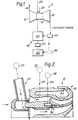
- the gas generator 10 is a gas turbine engine and comprises a compressor 12, a combustor 14 and a turbine 16.
- the combustor 14 can be of the annular type having a plurality of equispaced dual fuel injectors 18, each having a corresponding steam injector 20 receiving steam from the steam manifold 22.
- the dual fuel injectors each receive a supply of liquid fuel 24 from a liquid fuel manifold 26 and a supply of gas fuel 28 through an outer gas manifold 30.
- Each injector 18 has an inner annular liquid fuel passage 32 connected to the liquid fuel manifold 26 and an outer annular gas fuel passage 34 connected to the gas fuel manifold 30.
- the liquid and gas fuel passages 32 and 34 have outlet nozzles 36 and 38 respectively.
- the engine 10 operates in a conventional manner, that is, air is drawn from atmosphere by the compressor 12, is compressed and supplied to the combustor 14, where gas and liquid fuel is mixed with the compressed air and burnt.
- the products of combustion drive the turbine 16 which in turn drives the compressor 12.
- the exhaust from the turbine 16 can then be used to drive a load using a power turbine (not shown).
- waste heat from the exhaust can be used to raise steam in a waste heat recovery boiler 42 for injection into the gas generator 10, as explained below.
- the combustion process in engine 10 produces a number of undesirable emissions, notably unburned carbon and NOx.
- the level of NOx emissions can be controlled by the injection of steam into the primary zone of the combustor so as to cool the primary zone to a temperature below which most NOx is generated.
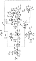
- the gas generator 10 has a steam supply and injection system generally indicated at 40 in Fig. 1 and shown in more detail in Fig. 3.
- the system 40 comprises steam supply plant, in this case a waste heat boiler 42 with integral header 44, a steam injection system 48 which is connected at its inlet to the header 44 and at its outlet to the steam manifold 22, and an electronic controller 50.
- the injection system 48 is connected to the header 44 via ducting 52 including a steam relief valve 54, a main isolation valve 56, and a non-return valve 58.
- a vent valve 60 and silencer 62 are connected to the ducting 52 as a side branch between the valves 54 and 56.
- Valve 54 is a safety feature and automatically blows off if for any reason the steam pressure becomes too high.
- Valves 56 and 60 are manually operated.
- Valve 56 is provided to isolate the entire gas turbine engine and injection system from the steam supply in case the engine is to be run without steam, e.g. because the boiler is down for maintenance.
- Valve 60 is provided to enable steam to be blown off readily to atmosphere if it is desired to generate steam for test or other purposes without feeding it into the injection system 48.
- the ducting 52 continues through the injection system 48 and is connected to the steam manifold 22.
- the ducting 52 connects: a strainer 64; a side branch consisting of a steam bleed-off or warm-up valve 66 and a silencer 68 vented to atmosphere; a steam shut-off cock 70; a non-return valve 72; another side branch consisting of a purge valve 74 with an upstream flow restriction 76; a flow meter 78; a steam metering valve 80; and a water and steam mixer or desuperheater 92.
- the desuperheater 92 is fed with water by another side branch 82 comprising in flow sequence a shut-off cock 84, a flow meter 86, a non-return valve 88, and a water metering valve 90.
- a drain valve 94 having an upstream flow restriction 96 is connected to the steam manifold 22 and vents to atmosphere.
- non-manually operated valves i.e., those which are servo operated on command from the controller 50
- small boxes S representing their servos.
- Each servo S has a command input from the controller 50 and a sensor output to the controller representing valve position.
- Valves 66,80 and 90 being metering valves, are proportionally controlled, with inputs and outputs Vip and Vop respectively, but the other non-manual valves are merely two position valves, with corresponding two-state inputs and outputs Vi and Vo respectively.
- the controller 50 receives inputs in the form of valve position signals Vop,Vo (proportional or on/off as appropriate for the valve), water flow rates Fw, steam flow rates Fs, and steam pressure and temperature, P,T. These data are of course input from the non-manual valves, steam flow meter 78, water flow meter 86, and various steam pressure and temperature sensors, shown as circled P and T symbols.
- the controller 50 also monitors pressure and temperature in the steam header 44. Acting on these inputs, controller 50 is responsible for the execution of the complete control scheme described below. This involves outputs Vi to control all two-position non-manual valves in the system in accordance with schedules and the operation of the proportionally controlled valves.
- the latter are controlled proportionally by signals Vip from the controller 50 representing scheduled operation and the results of calculations using feedback data Vop from the valves, the sensors P,T and the steam and water flow data, Fs,Fw.
- signals Vip from the controller 50 representing scheduled operation and the results of calculations using feedback data Vop from the valves, the sensors P,T and the steam and water flow data, Fs,Fw.
- the boiler/header 42/44 is a heat exchanger arrangement which will extract otherwise waste heat from the exhaust of the power turbine and use it to boil water.
- the design of the heat exchanger is such that, apart from the initial warm-up process of the plant, the amount of steam produced at the varying engine operating conditions where steam injection is needed, though variable according to power turbine exhaust temperature and volume, will always be more than sufficient to prevent substantial depletion of the supply of steam in the header in the event of a sudden transition to maximum steam demand for injection into the engine, due to suddenly increased load on the power turbine.
- the gas generator 10 is started and run up to minimum steam injection power with the valve 56 open and valves 70 and 66 closed.
- This operating point may vary according to the characteristics of the installation and local pollution control laws, but could be, say, about 50% load.
- the minimum steam injection power is reached, there is a period during which the boiler/header 42/44 warms up. As the steam begins to be generated, the warm up valve 66 and the shut off cock 70 remain closed until the pressure in the header increases to an adequate value, say about 100 p.s.i., 6.8 bar.
- Warm-up of the steam injection system then commences when the controller 50 modulates the warm up valve 66 to allow a small flow of steam through the ducting 52 and then through the steam warm-up valve 66, vent line and silencer 68 to atmosphere.
- the steam pressure P1 and flow rate from the steam header into the system 48 are increased by further opening of the steam warm-up valve 66 on a ramp schedule.
- the controller 50 also signals the boiler control 46 to increase the boiler heating rate appropriately. Steam pressure and temperature P1,T1 increase until they reach the required values and all the pipe work and valves have been warmed up as far as the shut-off cock 70 and purged of condensates.
- the warm up valve 66 is a reverse acting valve, i.e. it is permanently biased to the open position so that its servo requires energising all the time to keep it closed. Thus, if the servo or power supply fails, or if the servo receives no signal from the controller 50, the valve will automatically open as a safety precaution to avoid risks of overpressurizing the injection system.
- shut-off cock 70 While steam pressure and temperature is being increased in the above way, the apparatus downstream of the shut-off cock 70 is purged and heated using compressor delivery air from the compressor 12 of the gas generator.
- valves 74 and 94 are scheduled by the controller 50 to purge and preheat the steam ducting downstream of the shut-off cock 70 and to drain the steam manifold 22.
- the purge valve 74 is opened prior to the shut-off cock being opened and again after the shut-off cock 70 is closed.
- the purge valve 74 moves to the open position and the gas generator is operating at the desired power, a proportion of the compressor delivery air from the compressor 12 at the free surface of the steam injectors 22 will flow to atmosphere through the ducting 52, the steam metering valve 80 and the purge valve 74.
- the compressed air will therefore purge this portion of the steam injection system of any condensate, and as it is at a relatively high temperature it will also preheat the ducting and valves downstream of the shut-off cock 70.
- the controller 50 modulates the steam metering valve 80 to control the rate of temperature increase within acceptable limits by varying the restriction in the throttling area of the valve.
- the drain valve 94 is connected to atmosphere and to a collector block (not shown) on the steam manifold 22.
- the valve 94 is operated by the controller 50 while the shut-off cock 70 is shut and compressed air from the compressor 12 will flow through the steam injectors 20 into the steam manifold 22 and through the valve 94 to atmosphere, so that any condensate in the collector block will be exhausted to atmosphere rather than being ejected into the gas generator when the steam supply is turned on.
- the sequence of events for the operation of the valves 70,74,80 and 94 is as follows.
- the gas generator is operated at a required power with the shut-off cock 70 closed.
- the steam metering valve 80 is operated by the controller 50 to pass the air flow required for preheating the steam ducting, the controller also opening the purge valve 74 to obtain a through flow.
- the controller 50 schedules the air flow through this part of the system by comparing T1 and T2 and using valve 80 to control the rate of rise of T2.
- T2 is greater than or equal to T1 for a set period of time (say, 30 seconds)
- the shut-off cock 70 is commanded open and the steam metering valve 80 is operated to allow an initial steam flow.
- the amount of initial steam flow is determined by valve stability at low steam flows, and the ability of the gas generator to continue operating without surge or flame out.
- the controller 50 closes the purge valve 74 and also commands the steam warm-up valve 66 to close by an amount proportional to the initial steam flow into the gas generator, thereby maintaining constant steam input into the system 48.
- the drain valve 94 is finally closed after a further predetermined period of time, for example 30 seconds.
- the steam flow to the gas generator during normal operation of the steam injection system is controlled automatically by the controller 50 by modulating the steam flow through the steam metering valve 80 and simultaneously modulating the steam flow through the steam warm-up valve 66 in order to maintain a constant steam flow rate into the system 48 from the steam supply header.
- the controller 50 uses the warm-up valve as a bleed-off valve for venting excess steam to atmosphere.
- the frequency responses of the valves 66 and 80 are substantially identical so that during a transient operation of the gas generator the steam header output flow rate can be maintained at a constant value, even though the supply of steam to the engine is varied.
- the controller can not only quickly reschedule the steam supply to maintain a required steam/fuel ratio, but can also stop steam delivery to the manifold 22 completely during a slam deceleration to idle power conditions, thereby preventing flame out of the combustor due to excess steam injection.
- the value derived for Cg can then be used in another look up table to read off the required valve actuator position from the known valve characteristic. This currently required position can then be compared to the actual position of the valve actuator to derive an error signal and the error signal can then used to modulate the valve actuator position to achieve zero error.
- the temperature and pressure of the steam in the header 42 can be readily maintained at an optimum, giving an assured desired degree of superheat at the steam manifold 22. This assumes known boiler operational characteristics.
- the steam available to the injection system would be too hot for injection into the engine. This could be due, e.g., to particular steam generator characteristics or to sharing of the steam supply with a variable demand process.
- a steam condition would be indicated to the controller 50 by the sensed temperature T3 and pressure P3 at the steam manifold.
- the controller 50 would open the stop cock 84 in water supply branch 82 and then using information signaled from the water flow meter 86 and temperature and pressure sensors, schedule the water metering valve 90 and the steam metering valve 80 to inject water and steam into the mixer 92 as a de-superheating step to control the steam condition.
- the mixture should be homogenous.
- a non-return valve 88 is positioned between the flow meter 86 and the metering valve 90 as a precaution against back pressures from the mixer 92, which is of the vortex type.
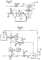
- Control of the steam and water metering valves for desuperheating will be described in more detail for Fig. 6.
- the controller 50 of the previous figures is shown as control algorithms 97 to 99 for the water metering valve 90 and algorithms 100 and 101 for the steam metering valve 80.
- the algorithm 97 receives the steam manifold pressure P 3 and temperature T 3 signals and calculates the degree of superheat Ts. This is compared in algorithm 98 with a predetermined set point Tm for correct steam injection conditions in the steam manifold 22. The deviation Td is fed to the water metering valve control algorithm 98, along with the water mass flow rate data from the meter 86. If the steam is too hot, the algorithm 98, which is of the proportional integral derivative type, increases the water flow to the mixer 92 by opening the water metering valve 90, and if the steam is too cool it reduces the water flow.
- the algorithm 100 is also receiving water mass flow data from meter 86 and steam temperature and pressure data T4,P4 from a position in the steam line 52 after the steam mass flow rate meter 78. Using these inputs, it calculates the amount of reduction ⁇ s needed in the steam flow rate through steam metering valve 80 to compensate for the flow of water into the mixer 92. The error value 6s is then fed into steam metering valve control algorithm 101 along with the actual steam mass flow rate data from the meter 78 in line 52, and the correct setting for the steam metering valve 80 is calculated and signaled to the valve.
- the gas manifold 30 of the gas generator can be provided with a condensate purging system.
- the gas fuel manifold 30 has a fuel supply line 108 with a high speed shut-off cock 110 controlled by signals 111 from the controller 50.
- a condensate purge valve 112 again controlled by signals 113 from the controller 50, is connected to the supply line 108 immediately after the gas shut-off cock 110 through a manual shut-off cock 114, which may be needed to facilitate maintenance.
- the valve 112 vents to atmosphere through a restriction 116.
- Fig. 7 enables any condensate which collects in the gas fuel manifold when the gas generator is operating on liquid fuel and steam injection to be vented to atmosphere.
- the removal of the condensate prevents the condensate being ejected into the gas generator when the fuel supply is transitioned, while the engine is running, from liquid fuel with steam injection to gas fuel with or without steam injection, or when the gas generator is restarted on gas fuel with or without steam injection, after it has been running on liquid fuel with steam injection.
- the purge valve 112 is only opened when the gas generator is running on liquid fuel with steam injection, the shut-off cock 110 being closed and the manual valve 114 open.
- the controller 50 opens the purge valve 112 and high pressure compressor delivery air and steam mixture is drawn from the gas generator through the purge holes in the gas fuel manifold 34 in each dual fuel injector 18. Any condensates are ejected from the gas fuel manifold 30 through the gas fuel supply line 108, the valves 114 and 112 and the restriction 116 to a safe area where personnel and equipment cannot be harmed.
- This gas manifold purge system is disabled by the controller while gas fuel is being used by the engine, and also while steam injection is not being used. In the scheduling of the valves by the controller 50, it is also ensured that when transferring from liquid to gas fuel, the gas shut-off cock 110 and the purge valve 112 are not open at the same time.
- restriction 116 enables the purge flow through the valve 112 to be reduced as required to prevent excessive bleed-off of high pressure air which would impair the performance of the engine.
- the steam injection and control system provides a number of advantages.
- the supply of steam to the injection system 48 can be controlled to a suitable excess value as convenient and the amount of steam injected into the combustor can be controlled by scheduling of the steam warm-up valve 66 together with the steam metering valve 80 to provide the steam mass flow demanded by the gas generator.
- the steam required by the gas generator is available rapidly and is independent of the response rate of the boiler or other steam supply system.
- steam shut-off cock 70 While the steam shut-off cock 70 is closed, steam can be used to preheat the steam ducting and valves upstream of the steam shut-off cock 70 by venting steam through the steam warm-up valve 66. At the same time, the portion of the apparatus downstream of the shut off cock 70 can be preheated and purged using compressor delivery air vented to atmosphere through the purge valve 74. The procedure is to open the steam metering valve 80 to about its 40% open position and then bleed air backwards through the system to heat it up. This preheating of the ducting and valves of the apparatus preserves the quality of the steam and prevents thermal shock to the valves.
- the steam metering valve 80 is repositioned to an initial flow demand position, which will give, say, about 10% of the currently required steam flow, and then the valve is progressively opened further to increase the steam flow steadily up to the required value. This procedure avoids premature extinction of the flame due to shock and over-rapid quenching of the combustion process.
Landscapes
- Engineering & Computer Science (AREA)
- Chemical & Material Sciences (AREA)
- Combustion & Propulsion (AREA)
- Mechanical Engineering (AREA)
- General Engineering & Computer Science (AREA)
- Engine Equipment That Uses Special Cycles (AREA)
- Feeding And Controlling Fuel (AREA)
Claims (9)
- Dampfeinspritzsystem (40) für einen Verbrennungsturbinen-Gasgenerator (10) mit den folgenden Merkmalen:- einer Dampfzuführungsvorrichtung (42, 44);- einer Dampfeinspritzeinrichtung (20, 22) zum Einspritzen von Dampf in den Gasgenerator (10);- einem Dampfzumeßventil (80) zur Zumessung der Dampfströmung nach der Dampfeinspritzeinrichtung (20, 22);- einem Dampfabzapfventil (66) zum Abzapfen von Dampf an einer Stelle des Systems stromauf des Dampfzumeßventils (80),dadurch gekennzeichnet, daß eine Steuervorrichtung (50) vorgesehen ist, die gleichzeitig das Dampfabzapfventil (66) und das Dampfzumeßventil (80) in einer Phasenbeziehung zueinander einstellt, um die vom Gasgenerator (10) geforderte Dampfströmung zu liefern, wobei das Zumeßventil (80) und das Abzapfventil (66) ein im wesentlichen identisches Frequenzansprechen besitzen, wodurch eine im wesentlichen konstante Dampfzufuhr von der Dampfzuführungsvorrichtung (42, 44) im Übergangsbereich des Gasgenerators (10) aufrechterhalten wird.
- Dampfeinspritzsystem nach Anspruch 1, bei welchem das Dampfabzapfventil (66) nach der Atmosphäre hin entlüftet ist.
- Dampfeinspritzsystem nach den Ansprüchen 1 oder 2, mit einem Absperrhahn stromab des Dampfabzapfpunktes (66), aber stromauf des Dampfzumeßventils (80).
- Dampfeinspritzsystem nach Anspruch 3, bei welchem eine Steuereinrichtung (50) vorgesehen ist, um den Absperrhahn (70) geschlossen zu halten, während der Dampfdruck und die Dampftemperatur auf die Arbeitswerte ansteigen, bevor Dampf in den Gasgenerator (10) eingespritzt wird, und zur gleichzeitigen Öffnung des Dampfabzapfventils (66) zur Entlüftung einer Dampfströmung durch das Abzapfventil (66), wodurch das Dampfeinspritzsystem (40) stromauf des Absperrhahns (70) vorgeheizt wird.
- Dampfeinspritzsystem nach einem der vorherigen Ansprüche 1 bis 4, bei welchem die Steuereinrichtung (50) das Dampfzumeßventil (80) derart einstellt, daß der Dampf durch das Dampfzumeßventil (80) mit einer Geschwindigkeit strömt, die vom Gasgenerator (10) gefordert wird, um innerhalb vorbestimmter Brennstoff:Dampf-Verhältnisgrenzen zu bleiben.
- Dampfeinspritzsystem nach einem der Ansprüche 1 bis 5, bei welchem die Dampfeinspritzeinrichtung (20, 22) stromab des Kompressors (12) des Gasgenerators (10) angeordnet ist.
- Dampfeinspritzsystem nach Anspruch 3, mit einer Steuereinrichtung (50) zum Schließen des Absperrhahns (70) und Öffnen des Dampfabzapfventils (66) und des Dampfzumeßventils (80) vor Beginn der Dampfeinspritzung in den Gasgenerator (10), damit Dampf aus der Dampfzuführungseinrichtung (42, 44) durch das Dampfabzapfventil (66) strömen kann und Luft vom Kompressor (12) des Gasgenerators (10) durch das Dampfzumeßventil (80) strömen kann, um dadurch das System vorzuheizen und zu spülen, und wobei die Steuermittel (50) den Absperrhahn (70) öffnen und das Dampfabzapfventil (66) und das Dampfzumeßventil (80) gemeinsam während der Einspritzung von Dampf in den Gasgenerator (10) derart einstellen, daß die Dampfzufuhr nach dem Gasgenerator (10) relativ zur Zuführung von Dampf aus der Dampfzuführungseinrichtung (42, 44) geändert wird.
- Dampfeinspritzsystem nach Anspruch 7, welches Mittel aufweist, um die Bedingungen des Dampfes in der Dampfeinspritzeinrichtung zu steuern.
- Dampfeinspritzsystem nach Anspruch 6, bei dem die Dampfeinspritzeinrichtung (20, 22) in der Verbrennungseinrichtung (14) des Gasgenerators (10) angeordnet ist.
Applications Claiming Priority (3)
| Application Number | Priority Date | Filing Date | Title |
|---|---|---|---|
| GB909025778A GB9025778D0 (en) | 1990-11-27 | 1990-11-27 | Improvements in or relating to gas generators |
| GB9025778 | 1990-11-27 | ||
| PCT/GB1991/002100 WO1992009791A2 (en) | 1990-11-27 | 1991-11-27 | Improvements in or relating to gas generators |
Publications (2)
| Publication Number | Publication Date |
|---|---|
| EP0559685A1 EP0559685A1 (de) | 1993-09-15 |
| EP0559685B1 true EP0559685B1 (de) | 1997-03-12 |
Family
ID=10686064
Family Applications (1)
| Application Number | Title | Priority Date | Filing Date |
|---|---|---|---|
| EP91920261A Expired - Lifetime EP0559685B1 (de) | 1990-11-27 | 1991-11-27 | Dampf-Einspritzsystem |
Country Status (6)
| Country | Link |
|---|---|
| US (3) | US5369951A (de) |
| EP (1) | EP0559685B1 (de) |
| CA (1) | CA2096011A1 (de) |
| DE (1) | DE69125168T2 (de) |
| GB (1) | GB9025778D0 (de) |
| WO (1) | WO1992009791A2 (de) |
Families Citing this family (47)
| Publication number | Priority date | Publication date | Assignee | Title |
|---|---|---|---|---|
| GB9025778D0 (en) * | 1990-11-27 | 1991-01-09 | Rolls Royce Plc | Improvements in or relating to gas generators |
| US5375409A (en) * | 1993-10-08 | 1994-12-27 | Ahlstrom Pyropower, Inc. | Pressurized fluidized bed combined gas turbine and steam turbine power plant with steam injection |
| DE19535370B4 (de) * | 1995-09-25 | 2006-05-11 | Alstom | Verfahren zur schadstoffarmen Vormischverbrennung in Gasturbinenbrennkammern |
| US6000211A (en) * | 1997-06-18 | 1999-12-14 | York Research Corporation | Solar power enhanced combustion turbine power plant and methods |
| US6145294A (en) * | 1998-04-09 | 2000-11-14 | General Electric Co. | Liquid fuel and water injection purge system for a gas turbine |
| EP0952317A3 (de) * | 1998-04-21 | 2002-04-17 | Mitsubishi Heavy Industries, Ltd. | Spülsystem für die Kraftstoffzufuhr einer Gasturbine |
| EP1199442A3 (de) * | 1998-05-08 | 2003-01-22 | Mitsubishi Heavy Industries, Ltd. | Spüleinrichtung für ein Kraftstoffsystem einer Gasturbine |
| AT408787B (de) * | 1998-05-29 | 2002-03-25 | Linzer Elek Zitaets Fernwaerme | Ölversorgungssystem für eine gasturbine |
| DE59810033D1 (de) * | 1998-09-16 | 2003-12-04 | Alstom Switzerland Ltd | Verfahren zum Minimieren thermoakustischer Schwingungen in Gasturbinenbrennkammern |
| US6145318A (en) * | 1998-10-22 | 2000-11-14 | General Electric Co. | Dual orifice bypass system for dual-fuel gas turbine |
| USRE40407E1 (en) | 1999-05-24 | 2008-07-01 | Vortex Flow, Inc. | Method and apparatus for mixing fluids |
| DE10041413B4 (de) * | 1999-08-25 | 2011-05-05 | Alstom (Switzerland) Ltd. | Verfahren zum Betrieb einer Kraftwerksanlage |
| US6393823B1 (en) * | 1999-11-05 | 2002-05-28 | General Electric Company | Methods for fuel nozzle staging for gas turbine engines |
| US6983603B2 (en) | 2002-10-24 | 2006-01-10 | Pratt & Whitney Canada Corp. | Detection of gas turbine engine hot section condition |
| US7104069B2 (en) * | 2003-06-25 | 2006-09-12 | Power Systems Mfg., Llc | Apparatus and method for improving combustion stability |
| DE102004004135A1 (de) * | 2004-01-28 | 2005-09-29 | Alstom Technology Ltd | Fördervorrichtung |
| JP4728176B2 (ja) * | 2005-06-24 | 2011-07-20 | 株式会社日立製作所 | バーナ、ガスタービン燃焼器及びバーナの冷却方法 |
| US7451602B2 (en) * | 2005-11-07 | 2008-11-18 | General Electric Company | Methods and apparatus for injecting fluids into turbine engines |
| US8033115B2 (en) * | 2006-01-05 | 2011-10-11 | General Electric Company | Water injection manifold pressure relief vent |
| US7600526B2 (en) * | 2006-07-20 | 2009-10-13 | General Electric Company | Methods and apparatus for operating steam turbines |
| US7841186B2 (en) * | 2007-01-31 | 2010-11-30 | Power Systems Mfg., Llc | Inlet bleed heat and power augmentation for a gas turbine engine |
| US9175606B2 (en) * | 2008-06-09 | 2015-11-03 | Siemens Aktiengesellschaft | Method for rinsing a fuel system of a gas turbine and associated fuel system |
| US7647777B2 (en) * | 2008-06-20 | 2010-01-19 | Gas Turbine Efficiency Sweden Ab | Skid architecture for a power augmentation system |
| US8381529B2 (en) * | 2009-01-29 | 2013-02-26 | General Electric Company | System and method for water injection in a turbine engine |
| CN101576248B (zh) * | 2009-06-04 | 2011-08-24 | 重庆新仪自控系统工程有限公司 | 注汽锅炉最优化运行控制系统 |
| EP2441936A1 (de) * | 2010-10-12 | 2012-04-18 | GE Energy Products France SNC | Gasturbine mit Wassereinspritzsteuerung |
| US9347377B2 (en) | 2010-10-28 | 2016-05-24 | Mitsubishi Hitachi Power Systems, Ltd. | Gas turbine and gas-turbine plant having the same |
| US8843240B2 (en) * | 2010-11-30 | 2014-09-23 | General Electric Company | Loading a steam turbine based on flow and temperature ramping rates |
| US9239013B2 (en) * | 2011-01-03 | 2016-01-19 | General Electric Company | Combustion turbine purge system and method of assembling same |
| US8991188B2 (en) | 2011-01-05 | 2015-03-31 | General Electric Company | Fuel nozzle passive purge cap flow |
| US8340886B2 (en) | 2011-03-07 | 2012-12-25 | General Electric Company | System and method for transitioning between fuel supplies for a combustion system |
| GB201107702D0 (en) * | 2011-05-10 | 2011-06-22 | Rolls Royce Plc | A steam injected gas turbine engine |
| US9188061B2 (en) * | 2011-10-24 | 2015-11-17 | General Electric Company | System for turbine combustor fuel assembly |
| US9650955B2 (en) * | 2011-11-10 | 2017-05-16 | General Electric Company | System for purging gas fuel circuit for a gas turbine engine |
| JP5946690B2 (ja) | 2012-05-02 | 2016-07-06 | 三菱日立パワーシステムズ株式会社 | ガスタービン燃焼器のパージ方法及びパージ装置 |
| US20140137564A1 (en) * | 2012-11-19 | 2014-05-22 | General Electric Company | Mitigation of Hot Corrosion in Steam Injected Gas Turbines |
| US9279369B2 (en) | 2013-03-13 | 2016-03-08 | General Electric Company | Turbomachine with transition piece having dilution holes and fuel injection system coupled to transition piece |
| US10731861B2 (en) | 2013-11-18 | 2020-08-04 | Raytheon Technologies Corporation | Dual fuel nozzle with concentric fuel passages for a gas turbine engine |
| DE102014212824A1 (de) * | 2014-07-02 | 2016-01-07 | Siemens Aktiengesellschaft | Verfahren und Vorrichtung zum Spülen und/oder Sperren wenigstens eines Brenners einer Gasturbinenanlage |
| US10526966B2 (en) | 2014-11-06 | 2020-01-07 | Powerphase Llc | Gas turbine efficiency and power augmentation improvements utilizing heated compressed air and steam injection |
| US10215060B2 (en) * | 2014-11-06 | 2019-02-26 | Powerphase Llc | Gas turbine efficiency and power augmentation improvements utilizing heated compressed air |
| US10378447B2 (en) | 2016-09-30 | 2019-08-13 | General Electric Company | System and method for purging fuel or coolant from turbomachine |
| US20220178544A1 (en) * | 2020-12-09 | 2022-06-09 | Pratt & Whitney Canada Corp. | Method of operating an aircraft engine and fuel system using multiple fuel types |
| US12486981B2 (en) * | 2023-03-28 | 2025-12-02 | General Electric Company | Conduit preheating control |
| US20250122833A1 (en) * | 2023-10-17 | 2025-04-17 | Ge Infrastructure Technology Llc | Airless sprint & water wash system |
| US20250163850A1 (en) * | 2023-11-21 | 2025-05-22 | General Electric Company | Turbine engine including a steam system |
| US12320293B1 (en) * | 2023-11-21 | 2025-06-03 | General Electric Company | Turbine engine including a steam system |
Family Cites Families (36)
| Publication number | Priority date | Publication date | Assignee | Title |
|---|---|---|---|---|
| GB186083A (en) * | 1921-03-24 | 1922-09-25 | Nikola Tesla | Improved method of and apparatus for the economic transformation of the energy of steam by turbines |
| US2959005A (en) * | 1958-06-04 | 1960-11-08 | Bbc Brown Boveri & Cie | Gas turbine plant and method of operating the same |
| US3353360A (en) * | 1966-02-18 | 1967-11-21 | Foster Wheeler Corp | Power plant with steam injection |
| US3705491A (en) * | 1970-06-30 | 1972-12-12 | Richard W Foster Pegg | Jet engine air compressor |
| US3693347A (en) * | 1971-05-12 | 1972-09-26 | Gen Electric | Steam injection in gas turbines having fixed geometry components |
| US3913314A (en) * | 1972-06-09 | 1975-10-21 | Westinghouse Electric Corp | System and method for operating a gas turbine electric power plant with bypass flow fueling operation to provide improved reliability and extended apparatus life |
| US3826080A (en) * | 1973-03-15 | 1974-07-30 | Westinghouse Electric Corp | System for reducing nitrogen-oxygen compound in the exhaust of a gas turbine |
| JPS5254824A (en) * | 1975-10-29 | 1977-05-04 | Toshiba Corp | Controlling device for combustor with vapor water injection device |
| US4157012A (en) * | 1977-03-24 | 1979-06-05 | General Electric Company | Gaseous fuel delivery system |
| DE2713831A1 (de) * | 1977-03-29 | 1978-10-05 | Heinrich Karl Dr I Feichtinger | Arbeitsverfahren fuer verbrennungskraftmaschinen mit zusatz von wasserdampf und verbrennungskraftmaschine fuer die durchfuehrung des verfahrens |
| US4148185A (en) * | 1977-08-15 | 1979-04-10 | Westinghouse Electric Corp. | Double reheat hydrogen/oxygen combustion turbine system |
| JPS54159519A (en) * | 1978-06-06 | 1979-12-17 | Nissan Motor Co Ltd | Dynamic valve device for internal combustion engine |
| JPS5855332B2 (ja) * | 1978-06-07 | 1983-12-09 | 株式会社日立製作所 | 二燃料焚き圧力噴霧式燃料ノズルのパ−ジ方法及び装置 |
| GB2034822A (en) * | 1978-11-15 | 1980-06-11 | Rolls Royce | Gas turbine engine cooling air supply |
| US4327547A (en) * | 1978-11-23 | 1982-05-04 | Rolls-Royce Limited | Fuel injectors |
| GB2050592B (en) * | 1979-06-06 | 1983-03-16 | Rolls Royce | Gas turbine |
| US4259837A (en) * | 1979-06-13 | 1981-04-07 | General Electric Company | Water and steam injection system for emission control of gas turbines |
| US4541367A (en) * | 1980-09-25 | 1985-09-17 | Owen, Wickersham & Erickson, P.C. | Combustion and pollution control system |
| US4442665A (en) * | 1980-10-17 | 1984-04-17 | General Electric Company | Coal gasification power generation plant |
| US4387559A (en) * | 1981-05-13 | 1983-06-14 | Curtiss-Wright Corporation | Fuel burner and combustor assembly for a gas turbine engine |
| GB2122333B (en) * | 1982-06-15 | 1985-08-14 | Rolls Royce | Improvements in or relating to dual fuel burners for gas turbine engines |
| DE3419560A1 (de) * | 1984-05-25 | 1985-11-28 | Brown, Boveri & Cie Ag, 6800 Mannheim | Verfahren zum betrieb einer gasturbinenanlage sowie anlage zur durchfuehrung des verfahrens |
| US4790269A (en) * | 1985-07-08 | 1988-12-13 | International Power Technology, Inc. | Method and apparatus for improved start-up procedures in conventional steam power generators and dual fluid cheng cycle engines |
| US4735043A (en) * | 1985-07-08 | 1988-04-05 | International Power Technology | Method and apparatus for improved start-up procedures in conventional steam power generators and dual fluid Cheng cycle engines |
| US4753068A (en) * | 1987-01-15 | 1988-06-28 | El Masri Maher A | Gas turbine cycle incorporating simultaneous, parallel, dual-mode heat recovery |
| DE3873281T2 (de) * | 1987-11-30 | 1993-03-18 | Gen Electric | Wasser-spray-auswerfer-system fuer motoren mit dampfeinspritzung. |
| US5095694A (en) * | 1988-02-16 | 1992-03-17 | Sundstrand Corporation | Fuel purging system for a turbine engine |
| US4984424A (en) * | 1988-02-16 | 1991-01-15 | Sundstrand Corporation | Fuel injection system for a turbine engine |
| GB2219070B (en) * | 1988-05-27 | 1992-03-25 | Rolls Royce Plc | Fuel injector |
| GB2219045B (en) * | 1988-05-27 | 1992-06-03 | Rolls Royce Plc | Gas turbine engine fuel system |
| US4893671A (en) * | 1988-06-20 | 1990-01-16 | Westinghouse Electric Corp. | Steam generator tube antivibration apparatus and method |
| US4969324A (en) * | 1988-07-13 | 1990-11-13 | Gas Research Institute | Control method for use with steam injected gas turbine |
| US4893467A (en) * | 1988-07-13 | 1990-01-16 | Gas Research Institute | Control system for use with steam injected gas turbine |
| GB2231651B (en) * | 1989-05-18 | 1991-10-16 | Rolls Royce Plc | Injector |
| GB9025778D0 (en) * | 1990-11-27 | 1991-01-09 | Rolls Royce Plc | Improvements in or relating to gas generators |
| US5365738A (en) * | 1991-12-26 | 1994-11-22 | Solar Turbines Incorporated | Low emission combustion nozzle for use with a gas turbine engine |
-
1990
- 1990-11-27 GB GB909025778A patent/GB9025778D0/en active Pending
-
1991
- 1991-11-27 US US08/070,338 patent/US5369951A/en not_active Expired - Lifetime
- 1991-11-27 EP EP91920261A patent/EP0559685B1/de not_active Expired - Lifetime
- 1991-11-27 CA CA002096011A patent/CA2096011A1/en not_active Abandoned
- 1991-11-27 DE DE69125168T patent/DE69125168T2/de not_active Expired - Fee Related
- 1991-11-27 WO PCT/GB1991/002100 patent/WO1992009791A2/en not_active Ceased
-
1994
- 1994-09-16 US US08/306,959 patent/US5540045A/en not_active Expired - Lifetime
-
1996
- 1996-02-20 US US08/619,895 patent/US5720164A/en not_active Expired - Lifetime
Also Published As
| Publication number | Publication date |
|---|---|
| DE69125168T2 (de) | 1997-06-19 |
| US5720164A (en) | 1998-02-24 |
| US5369951A (en) | 1994-12-06 |
| GB9025778D0 (en) | 1991-01-09 |
| US5540045A (en) | 1996-07-30 |
| DE69125168D1 (de) | 1997-04-17 |
| WO1992009791A3 (en) | 1992-10-01 |
| EP0559685A1 (de) | 1993-09-15 |
| CA2096011A1 (en) | 1992-05-28 |
| WO1992009791A2 (en) | 1992-06-11 |
Similar Documents
| Publication | Publication Date | Title |
|---|---|---|
| US5369951A (en) | Gas generators | |
| US5845481A (en) | Combustion turbine with fuel heating system | |
| RU2562681C2 (ru) | Газовая турбина с уменьшенными выбросами при частичной нагрузке | |
| EP1788309B1 (de) | Verfahren und Vorrichtung zum Betreiben von Gasturbinenantriebssystemen | |
| RU2665773C2 (ru) | Способ работы газотурбинной установки со ступенчатым и/или последовательным сгоранием | |
| US6519945B2 (en) | Method for controlling nitrogen injection into gas turbine | |
| EP0309485B1 (de) | Einen weiten bereich gasförmiger brennstoffe überdeckendes verbrennungssystem für gasturbinen | |
| US6977983B2 (en) | Nuclear power plant and a method of conditioning its power generation circuit | |
| CH697743A2 (de) | Gasturbinenmotorsystem mit Inline-Brennstoff-Reformierer sowie Verfahren zum Regeln der Wobbezahl eines Gasbrennstoffes. | |
| EP1124047B1 (de) | Doppelöffnungbypasssystem für Gasturbine mit Zweibrennstoffdüse | |
| US10443494B2 (en) | System and method for providing highly reactive fuels to a combustor | |
| RU2272964C2 (ru) | Способ и устройство для подачи топлива в камеру сгорания | |
| JPS597722A (ja) | ガスタ−ビン触媒燃焼器 | |
| US12454919B2 (en) | Exhaust cooling injection for improved turndown | |
| JP2019124134A5 (de) | ||
| JP3500710B2 (ja) | 燃料加熱ガスタービンプラント | |
| JPH0996227A (ja) | ガス化プラントの圧力制御装置 | |
| WO2015124909A1 (en) | Improved fuel supply system for a gas turbine | |
| JP3746634B2 (ja) | 蒸気温度制御装置 | |
| JPS6149486B2 (de) | ||
| RU2856551C2 (ru) | Устройство и способ запуска горелки газовой турбины | |
| JP3117392B2 (ja) | 排気再燃型複合プラントの起動方法 | |
| JP2025508033A (ja) | 高反応性燃料ガスの点火装置及び点火方法 | |
| CN118922620A (zh) | 用于高反应性燃料气体的点火装置和点火方法 | |
| JPH11270850A (ja) | ガスタービンプラントの燃料供給装置 |
Legal Events
| Date | Code | Title | Description |
|---|---|---|---|
| PUAI | Public reference made under article 153(3) epc to a published international application that has entered the european phase |
Free format text: ORIGINAL CODE: 0009012 |
|
| 17P | Request for examination filed |
Effective date: 19930517 |
|
| AK | Designated contracting states |
Kind code of ref document: A1 Designated state(s): DE FR GB |
|
| 17Q | First examination report despatched |
Effective date: 19950201 |
|
| GRAG | Despatch of communication of intention to grant |
Free format text: ORIGINAL CODE: EPIDOS AGRA |
|
| GRAH | Despatch of communication of intention to grant a patent |
Free format text: ORIGINAL CODE: EPIDOS IGRA |
|
| GRAH | Despatch of communication of intention to grant a patent |
Free format text: ORIGINAL CODE: EPIDOS IGRA |
|
| GRAA | (expected) grant |
Free format text: ORIGINAL CODE: 0009210 |
|
| AK | Designated contracting states |
Kind code of ref document: B1 Designated state(s): DE FR GB |
|
| REF | Corresponds to: |
Ref document number: 69125168 Country of ref document: DE Date of ref document: 19970417 |
|
| ET | Fr: translation filed | ||
| PLBE | No opposition filed within time limit |
Free format text: ORIGINAL CODE: 0009261 |
|
| STAA | Information on the status of an ep patent application or granted ep patent |
Free format text: STATUS: NO OPPOSITION FILED WITHIN TIME LIMIT |
|
| 26N | No opposition filed | ||
| REG | Reference to a national code |
Ref country code: GB Ref legal event code: IF02 |
|
| PGFP | Annual fee paid to national office [announced via postgrant information from national office to epo] |
Ref country code: DE Payment date: 20071029 Year of fee payment: 17 |
|
| PGFP | Annual fee paid to national office [announced via postgrant information from national office to epo] |
Ref country code: FR Payment date: 20071011 Year of fee payment: 17 Ref country code: GB Payment date: 20071018 Year of fee payment: 17 |
|
| GBPC | Gb: european patent ceased through non-payment of renewal fee |
Effective date: 20081127 |
|
| REG | Reference to a national code |
Ref country code: FR Ref legal event code: ST Effective date: 20090731 |
|
| PG25 | Lapsed in a contracting state [announced via postgrant information from national office to epo] |
Ref country code: DE Free format text: LAPSE BECAUSE OF NON-PAYMENT OF DUE FEES Effective date: 20090603 |
|
| PG25 | Lapsed in a contracting state [announced via postgrant information from national office to epo] |
Ref country code: GB Free format text: LAPSE BECAUSE OF NON-PAYMENT OF DUE FEES Effective date: 20081127 |
|
| PG25 | Lapsed in a contracting state [announced via postgrant information from national office to epo] |
Ref country code: FR Free format text: LAPSE BECAUSE OF NON-PAYMENT OF DUE FEES Effective date: 20081130 |