EP0559556A1 - Installation for producing corrugated cardboard - Google Patents
Installation for producing corrugated cardboard Download PDFInfo
- Publication number
- EP0559556A1 EP0559556A1 EP93400540A EP93400540A EP0559556A1 EP 0559556 A1 EP0559556 A1 EP 0559556A1 EP 93400540 A EP93400540 A EP 93400540A EP 93400540 A EP93400540 A EP 93400540A EP 0559556 A1 EP0559556 A1 EP 0559556A1
- Authority
- EP
- European Patent Office
- Prior art keywords
- roller
- installation
- cardboard
- smooth
- rollers
- Prior art date
- Legal status (The legal status is an assumption and is not a legal conclusion. Google has not performed a legal analysis and makes no representation as to the accuracy of the status listed.)
- Ceased
Links
Images


Classifications
-
- B—PERFORMING OPERATIONS; TRANSPORTING
- B31—MAKING ARTICLES OF PAPER, CARDBOARD OR MATERIAL WORKED IN A MANNER ANALOGOUS TO PAPER; WORKING PAPER, CARDBOARD OR MATERIAL WORKED IN A MANNER ANALOGOUS TO PAPER
- B31F—MECHANICAL WORKING OR DEFORMATION OF PAPER, CARDBOARD OR MATERIAL WORKED IN A MANNER ANALOGOUS TO PAPER
- B31F1/00—Mechanical deformation without removing material, e.g. in combination with laminating
- B31F1/20—Corrugating; Corrugating combined with laminating to other layers
- B31F1/24—Making webs in which the channel of each corrugation is transverse to the web feed
- B31F1/26—Making webs in which the channel of each corrugation is transverse to the web feed by interengaging toothed cylinders cylinder constructions
- B31F1/28—Making webs in which the channel of each corrugation is transverse to the web feed by interengaging toothed cylinders cylinder constructions combined with uniting the corrugated webs to flat webs ; Making double-faced corrugated cardboard
- B31F1/2845—Details, e.g. provisions for drying, moistening, pressing
- B31F1/285—Heating or drying equipment
-
- B—PERFORMING OPERATIONS; TRANSPORTING
- B31—MAKING ARTICLES OF PAPER, CARDBOARD OR MATERIAL WORKED IN A MANNER ANALOGOUS TO PAPER; WORKING PAPER, CARDBOARD OR MATERIAL WORKED IN A MANNER ANALOGOUS TO PAPER
- B31F—MECHANICAL WORKING OR DEFORMATION OF PAPER, CARDBOARD OR MATERIAL WORKED IN A MANNER ANALOGOUS TO PAPER
- B31F1/00—Mechanical deformation without removing material, e.g. in combination with laminating
- B31F1/20—Corrugating; Corrugating combined with laminating to other layers
- B31F1/24—Making webs in which the channel of each corrugation is transverse to the web feed
- B31F1/26—Making webs in which the channel of each corrugation is transverse to the web feed by interengaging toothed cylinders cylinder constructions
- B31F1/28—Making webs in which the channel of each corrugation is transverse to the web feed by interengaging toothed cylinders cylinder constructions combined with uniting the corrugated webs to flat webs ; Making double-faced corrugated cardboard
- B31F1/2845—Details, e.g. provisions for drying, moistening, pressing
- B31F1/2877—Pressing means for bringing facer sheet and corrugated webs into contact or keeping them in contact, e.g. rolls, belts
Definitions
- the present invention relates to an installation for producing corrugated cardboard.
- corrugated cardboard Traditionally, the production of corrugated cardboard consists in first corrugating the intermediate paper by inserting said paper between two rollers having corrugated surfaces whose profiled-section is identical to that required for the corrugated cardboard.
- the corrugated paper remains applied on one of the corrugating rollers under the action of a vacuum or of a positive pressure generated by the air blown inside a closed chamber which surrounds the mechanical parts from where the corrugations start in the paper to the area where the second paper is adhesively joined to the crests of the corrugations.
- This process is applied in continuous installations comprising devices for feeding strips of paper, a corrugating train, a storage of the one-layer corrugate (a smooth paper bonded to the crests on one side of the corrugated paper), one zone for drying the cardboard and another zone for cutting, slitting and stacking the cardboard sheets.
- This drying method does not make it possible to obtain a uniform drying or humidity over the various layers of paper, since the heat of the plates is conveyed to the upper layers of the cardboard by passing through the lower paper and since owing to the bad conductivity of the paper, great differences of temperatures are observed on the different layers.
- the strips of paper are fed from reel holders and automatically assembled "end-to-end".
- Another characteristic of the invention lies in the fact that the bonding of the first smooth layer is effected without any pressure being applied between the corrugating and the smooth roller.
- a clever solution is provided which enables the bonding of the first smooth layer of paper over the corrugated core without any pressure being exerted between the two rollers, thus avoiding the above-mentioned vibrations, and permitting an increase of the process speed.
- the first smooth paper which is bonded over the corrugated paper is maintained on the corrugating roller after the joining point of the two papers until a second smooth roller is reached, which roller is also a heating roller, thus making it possible to keep the two papers in contact with the heating rollers for a longer period and speeding up the adhesive drying process.
- the method used for drying the cardboard once the second smooth layer has been positioned is different from the conventional method using flat plates arranged in alignment, and employs two large heating rollers, which turn at a tangential speed which is equal to the speed of the cardboard, thereby avoiding any friction between the faces of the paper, and furthermore, the two drying rollers are arranged in such a way that the cardboard can receive heat on both faces, by passing from one roller to the other and by alternating the contact between the two faces. It receives the same quantity of heat on both faces, and comes out completely dry and with a uniformity of heat and humidity which enables it to be treated in continous manner.
- the method according to the invention in avoiding the conventional storage and passing directly from the corrugating train to the drying phase, permits a great saving in thermal energy while avoiding the cooling of the first two papers in the storage.
- this solution prevents the printed faces from deteriorating when preprinted paper is used.
- another basic characteristic of the present invention lies in the way in which the corrugated paper is held in close contact with the corrugating roller, from the corrugation point between the corrugating rollers up to its point of joining with the second paper.
- two hollow section pieces are provided, one between the corrugating rollers and the adhesive dosing roller, and the other between the dosing roller and the meeting point between the corrugated paper and the smooth paper.
- These section pieces are provided with orifices on the face adjacent to the corrugating roller conveying the corrugated paper. Pressurized air is injected at the ends of the section pieces and said air comes out through the orifices by exerting a sufficient pressure on the paper in order to keep it in contact with the corrugating roller.
- the corrugating roller is composed of a basic body on the surface of which a plurality of grooves are defined, said basic body being enclosed in a casing defining, with the grooves, steam pipes and vacuum pipes, the latter communicating with the outside, such that the inlet of steam and the outlet of condensation water occur at one end of the roller while the vacuum is transmitted at the other end; all this being such that a uniform heating of the whole surface of the roller is obtained as well as a vacuum which retains the paper at multiple points of the surface of the corrugating roller.
- the large cylinders for drying the cardboard are arranged so as to couple a system for continuously introducing printed sheets, this possibility giving the process the great advantage of allowing the small-scale manufacture of high quality boxes, at costs much lower than those required for small-scale printing with rotary printing machines.
- Figures 1 and 2 show by way of example a conventional installation for producing corrugated cardboard.
- This installation uses reel holders 6 fitted with conventional non"-end-to-end” assembling apparatus; such that where the strips of paper 2, 3 and 5 are joined up, their thickness is doubled and that when they pass through a corrugating machine 1, shakings and vibrations occur.
- the intermediate strip 2 passes between the two toothed rollers 7 which produce its corrugation and, once corrugated, said strip on the crests of the corrugations of one of its faces, the corresponding adhesive from the bonding machine 8 in order to ensure bonding of the first smooth layer of paper 3, the two layers 2 and 3 passing between one of the toothed rollers 7 and a smooth roller 10
- the rollers 7 and 10 are in pressurized contact together and as a result, due to the toothed form of the roller 7, shakings and vibrations occur after a certain speed is reached.
- the next step to the corrugating machine 1 is a storage 11 which is necessary to solve any problems which can arise with the joints between the strips of paper inside the reel holders 6.
- the next step is a zone in which the corrugated intermediate layer 2 receives an adhesive on its free face such that the second smooth layer of paper 5 can adhere thereon when passing onto a flat drying table 21 where final bonding and drying take place.
- friction of the cardboard on the fixed lower plates entails deformations thereof, including defects in any printed parts which the cardboard may comprise on its lower smooth face.
- the installation according to the invention comprises for feeding the sheets of paper 2, 3 and 5, respective feeding reel holders 6, which, in this case, are especially fitted with automatic "end-to-end” assembling machines for consecutively assembling the respective reels, such that, in this way, the excess thickness of the aforesaid sheets of paper is small, and that it does not correspond to twice the initial thickness as observed with the overlapping joints which are made with the conventional reel holders 6 of the conventional installations.
- the "end-to-end” assembling machines it is possible with the "end-to-end” assembling machines to obtain, for example if paper strips of three tenths of thickness are used, a joining thickness limited to a mere four tenths, against the six tenths obtained with the conventional solutions. This smaller thickness prevents the vibrations in the corrugating machine 1 and increases the speed.
- the reliability of "end-to-end" assembling machines makes it possible to eliminate the storage 11.
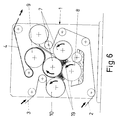
- the corrugating machine 1 of the installation according to the invention comprises a set of two toothed rollers 7 which are one into the other and between which the paper strip 2 to be corrugated passes, the latter thus acquires the corrugations which corresponds to the teeth of rollers 7 while, by means of the bonding machine 8, it is impregnated with adhesive on the crests of the corrugations of one of its faces, so that the first smooth layer 3 can be bonded over this strip, as shown in Figure 6.
- said unit 1 consists of an arrangement of elements which is such that both layers 2 and 3 remain on the output roller 7, although at a certain distance downstream of the assembly, remaining thereafter in resting contact around a contiguous heating drum 9 which it encircles nearly completely.
- Roller 9 turns at a tangential speed which is slightly greater than the speed of paper 3 and that of roller 10, in order to cause a pressurization or a tension on the paper 3 in the zone of contact with the toothed roller 7, thus enhancing the bonding quality thanks to the pressure applying the paper 3 on the crests of the corrugations and on the adhesive of the paper 2.
- the effect of the heating of the assembly 4 composed of layers 2 and 3, which is carried out by the drum 9 along the path covered by said assembly before coming out of the corrugating machine 1, is that the layers 2 and 3 are already assembled at the outlet from said unit with a degree of drying which makes it ready to be used in the next phase; this eliminating the other drawback of the conventional installations in which the storage 11 is necessary to ensure the drying of said assembly 4 of strips 2 and 3.
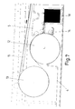
- the unit used for fastening the second smooth layer of paper 5 consists as shown in Figure 7, in the case of the installation according to the invention, in a set of two large rollers 12 and 13 on the first one of which the joined assembly composed of said layers 2 and 3 penetrates by resting on the smooth layer 3 and by encircling nearly completely said roller, such that, on this path, the second smooth layer of paper 5 positions itself on said assembly by adhering to the crests of the free corrugations of the corrugated layer 2 which have been impregnated beforehand with adhesive by means of a bonding machine 14.
- the assembly formed of the three layers 2, 3 and 5 passes from this roller 12 to the other roller 13, on which it rests via the strip 5, i.e. unlike the prior art technique, and on which roller 13 said assembly in turn rests nearly all around said roller, thereafter coming out thereof by resting on a conveyor belt 15 provided with a vacuum suction which facilitates the fixing and actuation, to lead said assembly constituting the cardboard up to the outlet where, by means of shears 16 and slitting machines 17, the formed cardboard is slit and cut so as to be collected in a final container 20.
- the two big rollers 12 and 13 turn at a tangential speed equal to the linear speed of the cardboard thus avoiding the friction on the faces of the cardboard.
- the rollers 12 and 13 are also heating rollers, such that the assembly constituting the cardboard is subjected to an efficient drying process while following the path where the second layer 5 is fixed, coming out towards the conveyor belt 15 without having to maintain a confinement above said conveyor belt and, such that this assembly constituting the cardboard covers its path without slipping on the bearing elements, thus preventing the surfaces of the outer faces where orusemental or informative printings may be applied from being scratched; there being, on the other hand, no risk of the corrugated intermediate layer 2 being deformed since there is no antagonistic frictions between the bearing elements and the pressure elements.
- this arrangement as well as the heating produced by the bearing rollers 12 and 13 result in the drying of the assembly constituting the aforesaid cardboard, is efficient and uniform throughout the thickness since, thanks to the fact that it rests first of all on the roller 12 via the face 3 and then, on the roller 13 via the other face 5, heating occurs through the two faces, such that it is truly efficient and uniform throughout the assembly.
- reference 19 designates section pieces which may be produced in aluminium or any other similar material, such that pressurized air may be brought in, and come out through corresponding orifices, provided on the faces in facing relationship with the toothed roller 7 contiguous to the smooth roller 10.
- section pieces 19 take advantage of the free spaces defined between the rollers 7, 8 and 10 in order to take up a priviledged position in which, acting as intake openings, they blow pressurized air onto the corresponding roller 7 so as to maintain the already corrugated layer of paper 2 in close contact with said roller 7, without this requiring any other fastening means.
- blowing section pieces 19 can either be located in other strategic points than those represented in Figure 6, or section pieces with a different configuration can be adopted without departing from the scope of the invention, which lies in the fact that the fastening of the corrugated layer 2 on the corresponding toothed roller 8 or the fastening of the assembly of layers 2 and 3 is obtained by applying pressurized air in localized spots, using blowing section pieces 19 arranged in strategic points.
- section pieces 19 can be completed or replaced by a particular embodiment of corrugating rollers 7 represented in Figures 10 and 11.
- Figure 10 shows that the roller 7 is composed of an inner body 22 on the surface of which are defined a series of grooves 24 and 25.
- the inner body 22 is surrounded by a sheath 23 thus forming pipes with the grooves 24 and 25, of which pipes those corresponding to the grooves 25 are used for circulating the steam and those corresponding to the grooves 24 are used for the vacuum.
- Grooves 24 open onto the outside through induction holes 26, such that each hole 26 gives rise to an induction point which makes it possible to maintain the paper in close contact with the roller 7.
- Figure 11 shows how the roller 7 is produced for this solution, according to a non-limiting example of practical embodiment.
- One end of the roller 7 is provided with inlet for the steam 27 which communicates with a steam collector 29 from which the grooves 25 start.
- the condensed steam returns through duct 32 up to outlet 34.
- the vacuum is created through the opening 31 located at the other end of the roller 7 and a vacuum collector is also provided wherefrom the grooves 24 start.
- the depth of the grooves 25, as shown in Figure 11, increase progressively so as to obtain a greater contact surface between the steam and the steel, in order to make the temperatures equal at both ends.
- two presses 17 are provided, which presses are rotary presses.
- one of them can be in operation while the cutting means are automatically changed on the other said means being conveyed from a magazine up to their mounting location, via a rolling bridge, such that said cutting means are ready for use without having to interrupt the operation.
- the very principle of rotary presses makes them more adaptable to the high speeds supported by the installation according to the invention.
- the corrugating machine 1 makes it possible, while retaining all of its main characteristics, to advance the position of its bonding machine 8 and to arrange the rollers 7, 9 and 10 such as to simplify the changing of the corrugating rollers 7.
- Figure 8 shows a solution in which the pair of toothed rollers 7 can be easily extracted by one side, merely by slightly tipping the bonding machine 8, such that once extracted, the pair can be cleaned up, replaced, etc...
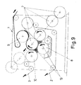
- Figure 9 shows another practical variant of embodiment in which a plurality of pairs of toothed rollers 7 are provided, said pairs being arranged diagonally and in such a way that either one of said pairs can be positioned selectively in its working position as a function of the needs of each operation.
Abstract
This installation comprises reel holders (6) provided with "end-to-end" assembling machines, a corrugating machine (1) in which the first bonding of the smooth layer is effected without any pressure being applied between the corregation roller (7) and the smooth roller (10), and two large heating cylinders (12 and 13) which turn at a tangential speed which is equal to the speed of the cardboard, said cylinders being arranged such that they can dry alternately, first one face of the cardboard, then the other. The contact between the corrugated paper and the corresponding corrugating roller (7) is obtained by the action of blowing section pieces (19) and/or by a particular embodiment of the roller (7).
Description
- The present invention relates to an installation for producing corrugated cardboard.
- Traditionally, the production of corrugated cardboard consists in first corrugating the intermediate paper by inserting said paper between two rollers having corrugated surfaces whose profiled-section is identical to that required for the corrugated cardboard. The corrugated paper remains applied on one of the corrugating rollers under the action of a vacuum or of a positive pressure generated by the air blown inside a closed chamber which surrounds the mechanical parts from where the corrugations start in the paper to the area where the second paper is adhesively joined to the crests of the corrugations.
- This process is applied in continuous installations comprising devices for feeding strips of paper, a corrugating train, a storage of the one-layer corrugate (a smooth paper bonded to the crests on one side of the corrugated paper), one zone for drying the cardboard and another zone for cutting, slitting and stacking the cardboard sheets.
- Heretofore, all the known embodiments have had problems in common which can be summed up as follows :
- A. - Speed. The conventional installations have reached their maximum speed which is of about 300 meters per minute and which cannot easily be exceeded, essentially for two reasons :
- The first layer of smooth paper is bonded over the corrugated paper inside the corrugating train, by compression between a smooth face cylinder and the corrugating roller on which is applied the corrugated paper, this causing the smooth roller, on reaching a certain speed, to jump against the corrugating roller and to create strong vibrations, which reduces quality standards after a certain speed.
The joining of the paper sheets doubles the thickness of the paper in the joining area thus causing a jump when the glued part is engaged between the two rollers. At high speeds, this causes the rollers to jump thus creating a zone of false corrugations and a delamination of the cardboard and resulting in interruptions and delays in the remainder of the operation. - B. - The storage of the first two sized papers results in a cooling of the papers, which papers must be reheated in the bonding phase of the next papers.
- C. - After bonding of the third paper, in the case of a one-layer cardboard with only one corrugation, or a two-layer cardboard in which all the papers are already bonded, the next step is the drying table comprising heating plates and a moving apron which drives the already shaped cardboard over the plates thus causing a friction of the paper in contact with the plates and consequently raising problems with regard to the face of the paper if it is a preprinted paper.
- This drying method does not make it possible to obtain a uniform drying or humidity over the various layers of paper, since the heat of the plates is conveyed to the upper layers of the cardboard by passing through the lower paper and since owing to the bad conductivity of the paper, great differences of temperatures are observed on the different layers.
- On the other hand, when the heat is transmitted upwards, the actual humidity of the paper runs out together with the water contained in the adhesive when the latter is drying under the effect of the contact of the paper with the heating plates, such that the cardboard comes out with an excessive humidity content in the top layers and a low humidity content in the lower layers, so that it takes several hours before the stacked cardboard sheets can be manipulated in the following processes, since the humidity of the cardboard has to be stabilized evenly throughout the sheet. This problem is an obstacle to the implementation of an integrated method for producing the cardboard box or packaging.
- These problems are solved with the process according to the invention by applying the solutions indicated hereinafter.
- The strips of paper are fed from reel holders and automatically assembled "end-to-end".
- This means that the two strips of paper are joined "end-to-end" by means of a very thin paper, such that, if the two strips to be assembled have a thickness of 0.3 mm and if they are assembled in superposition, both strips have a total thickness of 0.6 mm. On the contrary, if the two strips are assembled "end-to-end", and if they are joined with a 0.1 mm thick adhesive paper, the total thickness in the joining area is 0.4 mm rather than 0.6 mm. This difference makes it possible to assemble the paper at a much higher speed. On the other hand, the "end-to-end" assembling machines used in the process according to the invention reach speeds of almost 600 m/min. while ensuring a reliable assembly, thus eliminating the storage which is required with the conventional processes.
- Another characteristic of the invention lies in the fact that the bonding of the first smooth layer is effected without any pressure being applied between the corrugating and the smooth roller. A clever solution is provided which enables the bonding of the first smooth layer of paper over the corrugated core without any pressure being exerted between the two rollers, thus avoiding the above-mentioned vibrations, and permitting an increase of the process speed.
- Unlike the conventional corrugation method, the first smooth paper which is bonded over the corrugated paper is maintained on the corrugating roller after the joining point of the two papers until a second smooth roller is reached, which roller is also a heating roller, thus making it possible to keep the two papers in contact with the heating rollers for a longer period and speeding up the adhesive drying process.
- The method used for drying the cardboard once the second smooth layer has been positioned, is different from the conventional method using flat plates arranged in alignment, and employs two large heating rollers, which turn at a tangential speed which is equal to the speed of the cardboard, thereby avoiding any friction between the faces of the paper, and furthermore, the two drying rollers are arranged in such a way that the cardboard can receive heat on both faces, by passing from one roller to the other and by alternating the contact between the two faces. It receives the same quantity of heat on both faces, and comes out completely dry and with a uniformity of heat and humidity which enables it to be treated in continous manner.
- The method according to the invention, in avoiding the conventional storage and passing directly from the corrugating train to the drying phase, permits a great saving in thermal energy while avoiding the cooling of the first two papers in the storage.
- Also, this solution prevents the printed faces from deteriorating when preprinted paper is used.
- In addition to all said improvements, another basic characteristic of the present invention lies in the way in which the corrugated paper is held in close contact with the corrugating roller, from the corrugation point between the corrugating rollers up to its point of joining with the second paper.
- Indeed, this result is achieved in the conventional installations by a vacuum applied by the roller, or by air blown in from a large tight chamber inside the corrugation train.
- According to the invention, two hollow section pieces are provided, one between the corrugating rollers and the adhesive dosing roller, and the other between the dosing roller and the meeting point between the corrugated paper and the smooth paper. These section pieces are provided with orifices on the face adjacent to the corrugating roller conveying the corrugated paper. Pressurized air is injected at the ends of the section pieces and said air comes out through the orifices by exerting a sufficient pressure on the paper in order to keep it in contact with the corrugating roller.
- These section pieces, by tending to keep the pressure in one spot, eliminate the need for an expensive and complex pressurized chamber on top of the corrugating roller.
- The action of these blowing section pieces is meant to be completed by a particular embodiment of the corresponding corrugating roller, which may also eliminate the need for said section pieces. According to this embodiment, the corrugating roller is composed of a basic body on the surface of which a plurality of grooves are defined, said basic body being enclosed in a casing defining, with the grooves, steam pipes and vacuum pipes, the latter communicating with the outside, such that the inlet of steam and the outlet of condensation water occur at one end of the roller while the vacuum is transmitted at the other end; all this being such that a uniform heating of the whole surface of the roller is obtained as well as a vacuum which retains the paper at multiple points of the surface of the corrugating roller.
- Other basic characteristics include the fact that, it is possible with the new process, to provide two rotary presses at the end of the path which presses enable the boxes to be produced continuously, and can replace each other to allow changes in the format without having to stop the production line, as well as other details which will be more apparent on reading the following description and which, finally, make it possible to obtain an installation with one high-speed channel, for producing a corrugated cardboard in better conditions than those offered by the conventional installations.
- The large cylinders for drying the cardboard are arranged so as to couple a system for continuously introducing printed sheets, this possibility giving the process the great advantage of allowing the small-scale manufacture of high quality boxes, at costs much lower than those required for small-scale printing with rotary printing machines.
- Other characteristics and advantages of the invention will become more apparent on reading the following description of one example of embodiment given with reference to the accompanying drawings in which :
- Figure 1 is a diagrammatic illustration of a conventional installation for continuously producing corrugated cardboard;
- Figure 2 is a diagrammatic illustration, on a larger scale, of one detail of the corrugation unit of the aforesaid conventional installation;
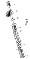
- Figure 3 is an overall diagrammatic perspective of an installation according to the object of the invention, and according to a non-restrictive example of a practical embodiment.
- Figure 4 is an elevational view of Figure 3;
- Figure 5 illustrates on a larger scale one part of the preceding Figure;
- Figure 6, illustrates on a larger scale one detail of the corrugation unit of the installation according to the invention;
- Figure 7 illustrates on a larger scale one detail corresponding to the part of the installation to which the second
smooth layer 5 is fixed by means of the printed paper feeder or by means of a printed reel.Rollers - Figures 8 and 9 illustrate diagrammatically the
corrugation unit 1, according to several practical ariants of said unit, with two sets of corrugating rollers being incorporated in said unit and being capabel of replacing each other by simple displacement; - Figure 10 shows a cross-section of a
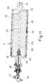
corrugating roller 7 according to a practical and possible variant embodiment of this roller; - Figure 11 is a longitudinal section of the
corrugating roller 7 of Figure 10. - Figures 1 and 2 show by way of example a conventional installation for producing corrugated cardboard. This installation uses
reel holders 6 fitted with conventional non"-end-to-end" assembling apparatus; such that where the strips ofpaper corrugating machine 1, shakings and vibrations occur. - On the other hand, as shown in Figure 2, in conventional
corrugating machines 1, theintermediate strip 2 passes between the twotoothed rollers 7 which produce its corrugation and, once corrugated, said strip on the crests of the corrugations of one of its faces, the corresponding adhesive from thebonding machine 8 in order to ensure bonding of the first smooth layer ofpaper 3, the twolayers toothed rollers 7 and asmooth roller 10 - To achieve bonding of the two
layers rollers roller 7, shakings and vibrations occur after a certain speed is reached. - In this conventional installation, the next step to the
corrugating machine 1 is astorage 11 which is necessary to solve any problems which can arise with the joints between the strips of paper inside thereel holders 6. - After this
storage 11, the next step is a zone in which the corrugatedintermediate layer 2 receives an adhesive on its free face such that the second smooth layer ofpaper 5 can adhere thereon when passing onto a flat drying table 21 where final bonding and drying take place. - To ensure the drying along the table 21, a felt tape is circulated which tape drives the cardboard over fixed lower plates which are steam-heated. This solution implies that the cardboard be heated only on one of its faces thus resulting in an inadequate drying and a loss of energy since the cardboard is a very bad conductor of heat.
- Moreover, friction of the cardboard on the fixed lower plates entails deformations thereof, including defects in any printed parts which the cardboard may comprise on its lower smooth face.
- According to the invention, and as shown in Figures 3 and 4, the installation according to the invention comprises for feeding the sheets of
paper feeding reel holders 6, which, in this case, are especially fitted with automatic "end-to-end" assembling machines for consecutively assembling the respective reels, such that, in this way, the excess thickness of the aforesaid sheets of paper is small, and that it does not correspond to twice the initial thickness as observed with the overlapping joints which are made with theconventional reel holders 6 of the conventional installations. In this way, it is possible with the "end-to-end" assembling machines to obtain, for example if paper strips of three tenths of thickness are used, a joining thickness limited to a mere four tenths, against the six tenths obtained with the conventional solutions. This smaller thickness prevents the vibrations in thecorrugating machine 1 and increases the speed. Moreover, the reliability of "end-to-end" assembling machines makes it possible to eliminate thestorage 11. - Furthermore, the corrugating
machine 1 of the installation according to the invention comprises a set of twotoothed rollers 7 which are one into the other and between which thepaper strip 2 to be corrugated passes, the latter thus acquires the corrugations which corresponds to the teeth ofrollers 7 while, by means of thebonding machine 8, it is impregnated with adhesive on the crests of the corrugations of one of its faces, so that the firstsmooth layer 3 can be bonded over this strip, as shown in Figure 6. - In the installation according to the invention, said
unit 1 consists of an arrangement of elements which is such that bothlayers output roller 7, although at a certain distance downstream of the assembly, remaining thereafter in resting contact around acontiguous heating drum 9 which it encircles nearly completely. - When comparing Figures 2 and 6, it is found that, in Figure 2 which shows the conventional installation, the
layers rollers layers toothed roller 7 then, they encircle most of theheating roller 9, thus ensuring a perfect assembly betweenlayers smooth roller 10, which is the member feeding and preheating the paper, and thecorrugating roller 7, a slight predetermined gap exists which prevents any contact between these two rollers, thus preventing the shocks which cause vibrations. -
Roller 9 turns at a tangential speed which is slightly greater than the speed ofpaper 3 and that ofroller 10, in order to cause a pressurization or a tension on thepaper 3 in the zone of contact with thetoothed roller 7, thus enhancing the bonding quality thanks to the pressure applying thepaper 3 on the crests of the corrugations and on the adhesive of thepaper 2. - Furthermore, owing to the fact that the contact between the joined
layers roller 10 to be pressed against the correspondingtoothed roller 7, in order to enable contact between the two layers ofpaper - In this way, the repeated knocking of said
rollers - In addition, since said
rollers layers layers reel holders 7 which are used in this case, enable the installation according to the invention to readily withstand a high feeding speed of thestrips - On the other hand, the effect of the heating of the
assembly 4 composed oflayers drum 9 along the path covered by said assembly before coming out of thecorrugating machine 1, is that thelayers storage 11 is necessary to ensure the drying of saidassembly 4 ofstrips - The unit used for fastening the second smooth layer of
paper 5 consists as shown in Figure 7, in the case of the installation according to the invention, in a set of twolarge rollers layers smooth layer 3 and by encircling nearly completely said roller, such that, on this path, the second smooth layer ofpaper 5 positions itself on said assembly by adhering to the crests of the free corrugations of thecorrugated layer 2 which have been impregnated beforehand with adhesive by means of abonding machine 14. - The assembly formed of the three
layers roller 12 to theother roller 13, on which it rests via thestrip 5, i.e. unlike the prior art technique, and on whichroller 13 said assembly in turn rests nearly all around said roller, thereafter coming out thereof by resting on aconveyor belt 15 provided with a vacuum suction which facilitates the fixing and actuation, to lead said assembly constituting the cardboard up to the outlet where, by means ofshears 16 and slittingmachines 17, the formed cardboard is slit and cut so as to be collected in afinal container 20. - The two
big rollers - The
rollers second layer 5 is fixed, coming out towards theconveyor belt 15 without having to maintain a confinement above said conveyor belt and, such that this assembly constituting the cardboard covers its path without slipping on the bearing elements, thus preventing the surfaces of the outer faces where ornemental or informative printings may be applied from being scratched; there being, on the other hand, no risk of the corrugatedintermediate layer 2 being deformed since there is no antagonistic frictions between the bearing elements and the pressure elements. - In another aspect, this arrangement as well as the heating produced by the bearing
rollers roller 12 via theface 3 and then, on theroller 13 via theother face 5, heating occurs through the two faces, such that it is truly efficient and uniform throughout the assembly. - With this arrangement of the installation according to the invention, it is further possible to incorporate the second
smooth layer 5, starting with a continuous strip fed from acorresponding reel holder 6 as well as with successive single sheets, supplied by afeeder 18, as shown in Figures 3, 4, 5 and 7. - Another essential characteristic of the invention is illustrated in Figure 6, in which reference 19 designates section pieces which may be produced in aluminium or any other similar material, such that pressurized air may be brought in, and come out through corresponding orifices, provided on the faces in facing relationship with the
toothed roller 7 contiguous to thesmooth roller 10. - In this way, the
section pieces 19 take advantage of the free spaces defined between therollers corresponding roller 7 so as to maintain the already corrugated layer ofpaper 2 in close contact with saidroller 7, without this requiring any other fastening means. - These blowing
section pieces 19 can either be located in other strategic points than those represented in Figure 6, or section pieces with a different configuration can be adopted without departing from the scope of the invention, which lies in the fact that the fastening of thecorrugated layer 2 on the correspondingtoothed roller 8 or the fastening of the assembly oflayers blowing section pieces 19 arranged in strategic points. - The action of
section pieces 19 can be completed or replaced by a particular embodiment ofcorrugating rollers 7 represented in Figures 10 and 11. - Figure 10 shows that the
roller 7 is composed of aninner body 22 on the surface of which are defined a series ofgrooves inner body 22 is surrounded by asheath 23 thus forming pipes with thegrooves grooves 25 are used for circulating the steam and those corresponding to thegrooves 24 are used for the vacuum. -
Grooves 24 open onto the outside through induction holes 26, such that eachhole 26 gives rise to an induction point which makes it possible to maintain the paper in close contact with theroller 7. - On the other hand, when steam covers the
grooves 25, a quick and uniform heating takes place throughout the surface ofroller 7, thus avoiding deformations of this roller, and the need to provide for immobilisation periods at the beginning of the operation until theroller 7, is heated as well as other similar problems. - Figure 11 shows how the
roller 7 is produced for this solution, according to a non-limiting example of practical embodiment. - One end of the
roller 7 is provided with inlet for thesteam 27 which communicates with asteam collector 29 from which thegrooves 25 start. - The condensed steam returns through
duct 32 up tooutlet 34. - The vacuum is created through the
opening 31 located at the other end of theroller 7 and a vacuum collector is also provided wherefrom thegrooves 24 start. - In order to establish the inlet and outlet of the steam through one of the ends of the
corrugating roller 7, there are provided a corresponding standardrotary joint 28 and a special rotary joint 33. - It should be noted that the depth of the
grooves 25, as shown in Figure 11, increase progressively so as to obtain a greater contact surface between the steam and the steel, in order to make the temperatures equal at both ends. - According to yet another characteristic of the invention, illustrated in Figure 3, two
presses 17 are provided, which presses are rotary presses. In this way, there being two such presses, one of them can be in operation while the cutting means are automatically changed on the other said means being conveyed from a magazine up to their mounting location, via a rolling bridge, such that said cutting means are ready for use without having to interrupt the operation. Furthermore, the very principle of rotary presses makes them more adaptable to the high speeds supported by the installation according to the invention. - The corrugating
machine 1 according to the invention makes it possible, while retaining all of its main characteristics, to advance the position of itsbonding machine 8 and to arrange therollers corrugating rollers 7. - For example Figure 8 shows a solution in which the pair of
toothed rollers 7 can be easily extracted by one side, merely by slightly tipping thebonding machine 8, such that once extracted, the pair can be cleaned up, replaced, etc... - Figure 9 shows another practical variant of embodiment in which a plurality of pairs of
toothed rollers 7 are provided, said pairs being arranged diagonally and in such a way that either one of said pairs can be positioned selectively in its working position as a function of the needs of each operation. - It should be noted that, for simplification purposes, the installation has been described and illustrated in its most simple variant, i.e. that which is used for obtaining corrugated cardboard comprising a single central
corrugated layer 2 and twosmooth layers corrugated layer 2. - The invention is not limited to the installation described hereinabove by way of example and non-restrictively and various modifications may be brought thereto by the man skilled in the art without departing from its scope.
Claims (8)
1. - Installation for producing corrugated cardboard, of the type comprising reel holders (6) for feeding strips of paper (2, 3 and 5) which, when assembled constitute the corrugated cardboard, in which the corrugation of the intermediate layer (2) and its bonding on one of the smooth layers (3) is effected first, then the other smooth layer (5) is bonded and the assembly is dried, characterized in that the reel holders (6) comprise "end-to-end" assembling machines, the corrugating machine (1) comprises, at the outlet of the assembly constituted of the corrugated intermediate layer (2) and of the first smooth layer (3), a heating roller (9) whose strategic situation obliges the assembly of layers (2 and 3) to cover a path in which it is first of all with the corresponding toothed roller (7), and then with the heating roller (9), thus ensuring the necessary bonding between the layers (2 and 3) and the drying of the assembly.
2. - Installation for producing corrugated cardboard according to claim 1, characterized in that the corrugating machine (1) comprises on the inside, in positions distributed so as to take advantage of the free spaces defined between the different rollers (7, 8 and/or 10), intake section pieces (19) blowing air under pressure onto strategically localized and distributed zones so as to maintain the corrugated layer of paper (2) in close contact with the corresponding toothed roller (7).
3. - Installation for producing corrugated cardboard according to claim 1, characterized in that it comprises two large rotary rollers (12 and 13) where the assembly constituted of the corrugated intermediate layer (2) and the first smooth layer (3) arrives, such that, in the first large roller (12), said assembly is arranged such that the smooth layer (3) comes into contact with the drum and that the free crests of the corrugations of the corrugated layer (2) are facing outwardly in order to receive an adhesive enabling the bonding of the second smooth layer (5), while on passing over the second large roller (13), the arrangement of the cardboard is reversed, the smooth layer (5) being now in contact with the roller (13) and the smooth layer (3) facing outwardly, said large rollers (12 and 13) turning at a tangential speed which is equal to the speed of the cardboard, thus preventing any friction.
4. - Installation for producing corrugated cardboard according to claim 1, characterized in that the toothed roller (7) and the smooth roller (10), between which the corrugated intermediate layer (2) and the first smooth layer (3) are assembled together, are arranged such that there is no physical contact between them, or such that a sliding adjustment can occur without one pressing against the other.
5. - Installation for producing corrugated cardboard according to claim 1, characterized in that at the end of the installation, there is provided a pair of rotary presses (17) equipped with automatic means for changing their cutting elements.
6 - Installation for producing corrugated cardboard according to claim 1, characterized in that the two large rollers (12 and 13) are heating rollers, which, together with the fact that, thanks to their arrangement, the cardboard first comes into contact with the drum (12) by its smooth face (3) and then with the roller (13) by its smooth face (5), makes it possible to obtain a uniform drying of the cardboard on both its faces, while preventing deformations of the cardboard.
7. - Installation for producing corrugated cardboard according to claims 1 and 2, characterized in that the corrugating rollers (7) are composed of an inner body (22) on the surface of which are provided a series of grooves (24 and 25) which grooves define, with an outer body or a sheath (23) of the roller (7), ducts which are intended for the vacuum and for the steam respectively, the first one of these grooves (24 and 25) opening onto the outside surface of the roller (7) through suction holes (26) and communicating with the corresponding vacuum source through one of the ends of the corrugating roller (7), while its other end constitutes an inlet for the steam and an outlet for the condensate, which latter is collected beforehand in a central duct (32).
8. - Installation for producing corrugated cardboard according to claims 1 and 3, characterized in that an automatic sheet feeder (18) is provided in combination with a large roller (12) which feeder enables the second smooth layer (5) to be selectively replaced by a succession of independent sheets.
Applications Claiming Priority (2)
| Application Number | Priority Date | Filing Date | Title |
|---|---|---|---|
| ES9200456 | 1992-03-02 | ||
| ES9200456A ES2053377B1 (en) | 1992-03-02 | 1992-03-02 | SYSTEM FOR THE MANUFACTURE OF CORRUGATED CARDBOARD. |
Publications (1)
| Publication Number | Publication Date |
|---|---|
| EP0559556A1 true EP0559556A1 (en) | 1993-09-08 |
Family
ID=8276248
Family Applications (1)
| Application Number | Title | Priority Date | Filing Date |
|---|---|---|---|
| EP93400540A Ceased EP0559556A1 (en) | 1992-03-02 | 1993-03-02 | Installation for producing corrugated cardboard |
Country Status (5)
| Country | Link |
|---|---|
| EP (1) | EP0559556A1 (en) |
| JP (2) | JP3406344B2 (en) |
| AU (1) | AU3386193A (en) |
| CA (1) | CA2090661A1 (en) |
| ES (1) | ES2053377B1 (en) |
Cited By (16)
| Publication number | Priority date | Publication date | Assignee | Title |
|---|---|---|---|---|
| ES2070726A2 (en) * | 1993-03-24 | 1995-06-01 | Torres Martinez M | Paper-corrugating roller for corrugated cardboard |
| EP0657275A1 (en) * | 1993-12-08 | 1995-06-14 | BHS Corrugated Maschinen- und Anlagenbau GmbH | Corrugating roller for the manufacture of corrugated paper |
| FR2719521A1 (en) * | 1994-05-06 | 1995-11-10 | Otor Sa | Machine and method for producing a single-sided corrugated sheet by bonding under tension. |
| EP0750986A2 (en) * | 1995-06-26 | 1997-01-02 | Marquip, Inc. | Improved web holddown and drive for corrugator double backer |
| EP0753400A1 (en) * | 1995-07-14 | 1997-01-15 | Scm Container Machinery Limited | Apparatus for producing corrugated paperboard |
| GR1002719B (en) * | 1996-06-18 | 1997-06-10 | Mechanism and method for the production of undulated paper of any desiered width by pasting together two paper rolls of different sizes: - width-in a machine for undulated paper production. | |
| GB2313135A (en) * | 1996-05-14 | 1997-11-19 | Isowa Kk | Corrugating:single facer |
| WO1998003331A1 (en) * | 1996-07-23 | 1998-01-29 | Otor | Machine and method for making a sheet of single-face corrugated paperboard using traction feed prior to rolls |
| ES2110871A2 (en) * | 1994-03-16 | 1998-02-16 | Talleres Iruna S A | Improvements to vapour (steam) systems |
| EP0829693A1 (en) * | 1996-09-12 | 1998-03-18 | Talleres Iruna, S.A. | Improvements to corugating rollers heated by steam |
| EP0976540A2 (en) * | 1998-07-30 | 2000-02-02 | Ingg. Terzaghi & De Castiglione Industriale S.p.A. | Device for the production of corrugated cardboard with a single flat surface |
| EP1484171A2 (en) * | 2003-06-04 | 2004-12-08 | FOSBER S.p.A. | Corrugating roller for machines to produce corrugated cardboard and machine comprising said roller |
| EP1980389A1 (en) * | 2007-04-13 | 2008-10-15 | Aiki Kogyo Kabushiki Kaisha | Apparatus for producing corrugated cardboard |
| CN110053313A (en) * | 2019-03-13 | 2019-07-26 | 抚顺东旭精工制辊科技有限公司 | A kind of vacuum suction Corrugator roller |
| CN113371489A (en) * | 2021-05-30 | 2021-09-10 | 许金祥 | Conveying device is made in corrugated container board's integration |
| CN113684713A (en) * | 2021-08-17 | 2021-11-23 | 浙江森然工贸有限公司 | Production process and processing equipment of environment-friendly corrugated composite paperboard made of waste corrugated paper |
Families Citing this family (4)
| Publication number | Priority date | Publication date | Assignee | Title |
|---|---|---|---|---|
| JP2007106054A (en) * | 2005-10-14 | 2007-04-26 | Aiki Kogyo Kk | Corrugated cardboard manufacturing apparatus |
| CN103419411A (en) * | 2013-08-14 | 2013-12-04 | 朱丹华 | Throttle control structure of corrugated roll |
| CN110588084B (en) * | 2019-09-18 | 2021-03-19 | 浦江丰收包装有限公司 | Waterproof high-strength corrugated carton processing method |
| CN112389069B (en) * | 2020-11-06 | 2022-09-23 | 新疆訫美包装有限公司 | Guide preheating device and heating method for corrugated paper production |
Citations (3)
| Publication number | Priority date | Publication date | Assignee | Title |
|---|---|---|---|---|
| EP0229338A2 (en) * | 1985-12-19 | 1987-07-22 | Europa Carton Aktiengesellschaft | Method for making blanks of corrugated cardboard having a decorative surface |
| GB2194974A (en) * | 1986-09-09 | 1988-03-23 | Rengo Co Ltd | Corrugating machine |
| DE8909841U1 (en) * | 1989-08-17 | 1989-10-05 | Bhs-Bayerische Berg-, Huetten- Und Salzwerke Ag, 8000 Muenchen, De |
Family Cites Families (4)
| Publication number | Priority date | Publication date | Assignee | Title |
|---|---|---|---|---|
| DE3232774C2 (en) * | 1982-09-03 | 1986-06-19 | Werner H.K. Peters Maschinenfabrik Gmbh, 2000 Hamburg | Single sided corrugator |
| BR8800608A (en) * | 1987-02-18 | 1988-09-27 | Amcor Ltd | APPARATUS AND METHOD FOR MANUFACTURING CORRUGATED PAPER WITH FACE SINGLE |
| FI891649A (en) * | 1989-04-06 | 1990-10-07 | Enso Gutzeit Oy | FOERFARANDE FOER TILLVERKNING AV WELLPAPP ELLER DYLIKT. |
| ES2013482A6 (en) * | 1989-05-04 | 1990-05-01 | Torres Martinez M | Automatic splicer for paper strip suppliers |
-
1992
- 1992-03-02 ES ES9200456A patent/ES2053377B1/en not_active Expired - Fee Related
-
1993
- 1993-02-26 AU AU33861/93A patent/AU3386193A/en not_active Abandoned
- 1993-03-01 CA CA 2090661 patent/CA2090661A1/en not_active Abandoned
- 1993-03-02 JP JP06613893A patent/JP3406344B2/en not_active Expired - Fee Related
- 1993-03-02 EP EP93400540A patent/EP0559556A1/en not_active Ceased
-
2003
- 2003-01-17 JP JP2003010255A patent/JP2003181957A/en active Pending
Patent Citations (3)
| Publication number | Priority date | Publication date | Assignee | Title |
|---|---|---|---|---|
| EP0229338A2 (en) * | 1985-12-19 | 1987-07-22 | Europa Carton Aktiengesellschaft | Method for making blanks of corrugated cardboard having a decorative surface |
| GB2194974A (en) * | 1986-09-09 | 1988-03-23 | Rengo Co Ltd | Corrugating machine |
| DE8909841U1 (en) * | 1989-08-17 | 1989-10-05 | Bhs-Bayerische Berg-, Huetten- Und Salzwerke Ag, 8000 Muenchen, De |
Cited By (23)
| Publication number | Priority date | Publication date | Assignee | Title |
|---|---|---|---|---|
| ES2070726A2 (en) * | 1993-03-24 | 1995-06-01 | Torres Martinez M | Paper-corrugating roller for corrugated cardboard |
| EP0657275A1 (en) * | 1993-12-08 | 1995-06-14 | BHS Corrugated Maschinen- und Anlagenbau GmbH | Corrugating roller for the manufacture of corrugated paper |
| ES2110871A2 (en) * | 1994-03-16 | 1998-02-16 | Talleres Iruna S A | Improvements to vapour (steam) systems |
| FR2719521A1 (en) * | 1994-05-06 | 1995-11-10 | Otor Sa | Machine and method for producing a single-sided corrugated sheet by bonding under tension. |
| WO1995030537A1 (en) * | 1994-05-06 | 1995-11-16 | Otor | Machine and method of manufacture of single-face corrugated board by traction glueing |
| US6068724A (en) * | 1994-05-06 | 2000-05-30 | Otor | Machine and method for manufacture of a sheet of single-face corrugated board by gluing under tension |
| AU703956B2 (en) * | 1994-05-06 | 1999-04-01 | Otor | Machine and method for the manufacture of single-face corrugated cardboard |
| EP0750986A2 (en) * | 1995-06-26 | 1997-01-02 | Marquip, Inc. | Improved web holddown and drive for corrugator double backer |
| EP0750986A3 (en) * | 1995-06-26 | 1997-05-07 | Marquip Inc | Improved web holddown and drive for corrugator double backer |
| EP0753400A1 (en) * | 1995-07-14 | 1997-01-15 | Scm Container Machinery Limited | Apparatus for producing corrugated paperboard |
| US6289960B1 (en) | 1996-05-14 | 2001-09-18 | Kabushiki Kaisha Isowa | Apparatus having a wrapped roll for making a single faced corrugated board |
| GB2313135A (en) * | 1996-05-14 | 1997-11-19 | Isowa Kk | Corrugating:single facer |
| GR1002719B (en) * | 1996-06-18 | 1997-06-10 | Mechanism and method for the production of undulated paper of any desiered width by pasting together two paper rolls of different sizes: - width-in a machine for undulated paper production. | |
| WO1998003331A1 (en) * | 1996-07-23 | 1998-01-29 | Otor | Machine and method for making a sheet of single-face corrugated paperboard using traction feed prior to rolls |
| EP0829693A1 (en) * | 1996-09-12 | 1998-03-18 | Talleres Iruna, S.A. | Improvements to corugating rollers heated by steam |
| EP0976540A2 (en) * | 1998-07-30 | 2000-02-02 | Ingg. Terzaghi & De Castiglione Industriale S.p.A. | Device for the production of corrugated cardboard with a single flat surface |
| EP0976540A3 (en) * | 1998-07-30 | 2001-01-17 | Ingg. Terzaghi & De Castiglione Industriale S.p.A. | Device for the production of corrugated cardboard with a single flat surface |
| EP1484171A2 (en) * | 2003-06-04 | 2004-12-08 | FOSBER S.p.A. | Corrugating roller for machines to produce corrugated cardboard and machine comprising said roller |
| EP1484171A3 (en) * | 2003-06-04 | 2005-08-10 | FOSBER S.p.A. | Corrugating roller for machines to produce corrugated cardboard and machine comprising said roller |
| EP1980389A1 (en) * | 2007-04-13 | 2008-10-15 | Aiki Kogyo Kabushiki Kaisha | Apparatus for producing corrugated cardboard |
| CN110053313A (en) * | 2019-03-13 | 2019-07-26 | 抚顺东旭精工制辊科技有限公司 | A kind of vacuum suction Corrugator roller |
| CN113371489A (en) * | 2021-05-30 | 2021-09-10 | 许金祥 | Conveying device is made in corrugated container board's integration |
| CN113684713A (en) * | 2021-08-17 | 2021-11-23 | 浙江森然工贸有限公司 | Production process and processing equipment of environment-friendly corrugated composite paperboard made of waste corrugated paper |
Also Published As
| Publication number | Publication date |
|---|---|
| JP3406344B2 (en) | 2003-05-12 |
| CA2090661A1 (en) | 1993-09-03 |
| ES2053377R (en) | 1995-08-16 |
| JP2003181957A (en) | 2003-07-03 |
| JPH0623884A (en) | 1994-02-01 |
| ES2053377B1 (en) | 1996-01-16 |
| AU3386193A (en) | 1993-09-09 |
| ES2053377A2 (en) | 1994-07-16 |
Similar Documents
| Publication | Publication Date | Title |
|---|---|---|
| EP0559556A1 (en) | Installation for producing corrugated cardboard | |
| KR960037270A (en) | Multi corrugated cardboard forming method and apparatus | |
| AU678909B2 (en) | Double-ply corrugated paperboard | |
| CA2055403C (en) | Assembling device for weblike workpieces consisting of superposed and glued layers designed for being used with a double-facer of a machine producing corrugated board | |
| US5766410A (en) | Corrugating machine with an elastic press plate | |
| US20050139312A1 (en) | Corrugating machine | |
| JPH0532280Y2 (en) | ||
| GB2144077A (en) | Improvement in or related to corrugated products | |
| US5071507A (en) | Pasting machine in a corrugator | |
| US5996246A (en) | Edge seal for vacuum preheater | |
| JP2622330B2 (en) | Single side corrugated board making machine | |
| JP3416407B2 (en) | Corrugator | |
| US3567554A (en) | Method and apparatus for combining printed sheets with single face corrugated paper | |
| JP2919824B1 (en) | Double facer | |
| SU1301894A1 (en) | Method of producing moisture-proof corrugated board | |
| SU1715656A1 (en) | Line for making corrugated cardboard | |
| JPS59109345A (en) | Double facer of corrugating machine | |
| JP3787007B2 (en) | Method for manufacturing cross corrugated sheet laminate | |
| JP3509801B2 (en) | Corrugated sheet warpage prevention device | |
| SU1757906A1 (en) | Method of making strips of corrugated cardboard and apparatus for carrying out the method | |
| FI59358B (en) | VAERMEFOERSEGLINGSAPPARAT | |
| GB2263486A (en) | Producing corrugated sheets | |
| JP2002113799A (en) | Method for manufacturing double side corrugated board and manufacturing device therefor | |
| JPH06286032A (en) | Single-faced corrugated board manufacturing apparatus | |
| SU855106A1 (en) | Glueing section of machine for producing multilayer panels |
Legal Events
| Date | Code | Title | Description |
|---|---|---|---|
| PUAI | Public reference made under article 153(3) epc to a published international application that has entered the european phase |
Free format text: ORIGINAL CODE: 0009012 |
|
| AK | Designated contracting states |
Kind code of ref document: A1 Designated state(s): BE DE DK FR GB GR IE IT LU NL PT SE |
|
| 17P | Request for examination filed |
Effective date: 19940304 |
|
| 17Q | First examination report despatched |
Effective date: 19950808 |
|
| GRAG | Despatch of communication of intention to grant |
Free format text: ORIGINAL CODE: EPIDOS AGRA |
|
| STAA | Information on the status of an ep patent application or granted ep patent |
Free format text: STATUS: THE APPLICATION HAS BEEN REFUSED |
|
| 18R | Application refused |
Effective date: 19961021 |