EP0558462B1 - Lever device to control the taps of hobs and gas cookers - Google Patents
Lever device to control the taps of hobs and gas cookers Download PDFInfo
- Publication number
- EP0558462B1 EP0558462B1 EP93830077A EP93830077A EP0558462B1 EP 0558462 B1 EP0558462 B1 EP 0558462B1 EP 93830077 A EP93830077 A EP 93830077A EP 93830077 A EP93830077 A EP 93830077A EP 0558462 B1 EP0558462 B1 EP 0558462B1
- Authority
- EP
- European Patent Office
- Prior art keywords
- lever
- rod
- control
- rotation
- axis
- Prior art date
- Legal status (The legal status is an assumption and is not a legal conclusion. Google has not performed a legal analysis and makes no representation as to the accuracy of the status listed.)
- Expired - Lifetime
Links
Images
Classifications
-
- F—MECHANICAL ENGINEERING; LIGHTING; HEATING; WEAPONS; BLASTING
- F24—HEATING; RANGES; VENTILATING
- F24C—DOMESTIC STOVES OR RANGES ; DETAILS OF DOMESTIC STOVES OR RANGES, OF GENERAL APPLICATION
- F24C3/00—Stoves or ranges for gaseous fuels
- F24C3/12—Arrangement or mounting of control or safety devices
- F24C3/126—Arrangement or mounting of control or safety devices on ranges
Definitions
- the present invention concerns a lever device to control the taps of hobs and gas cookers.
- a knob is usually provided on the control rod, with a grip shaped so as to be suitable not only for the rotation but also to exert a certain pressure on it.
- a push button has been adopted for the axial shifting only, separate from the rotation knob.
- the knob and the push button are on the axis of the control rod of the taps, which are usually positioned near the burners, in particular in the case of hobs, with consequent dangerous approaching of the user's hands, during the operation, to heat sources or even, during the ignition, to flames whose range can not be previously evaluated.
- This object has been achieved through an extended control lever having an outer operating end and an inner reacting end, directed towards the flames, a slot being provided between the two ends for the passage of the tap control rod having, for a certain length from the free end thereof, a reduced section defined by two planes parallel to the axis, suitable to engage with a minimum clearance the side edges of said slot for the rotation, as well as a transverse seat, corresponding to the rod section widening in the direction perpendicular to its axis where said planes parallel to the axis end, the inner end of said lever being constrained in its motion in the direction parallel to the axis of the rod by a cover surface thereof, but free to slide along said surface.
- said outer end of the lever is knob-shaped to make the grip easier during the operation and the inner end preferably has a rounded shape to reduce the friction against the sliding surface during the rotation.
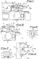
- a lever device 1 according to the invention is shown near the flames area 2 of a hob to control a gas supply tap 10.
- the hob is just an example application of the above-mentioned device, but the domestic cooking apparatus could as well be for example a gas or mixed type cooker.
- the flames area 2 with its related grill 4 is separated from the lever control device 1 by means of a wall 5 of protection from the flame and, by each tap, a horizontal appendix 5a extends, preferably of circular shape as best shown in the plan view of fig.3.
- each tap 10 has a vertical rotation axis preferably concentric with the circular surface of said protecting area 5a.
- the terms “horizontal” and “vertical " are obviously referred to the shown embodiment of a hob 2 with vertical taps, whereas if the device according to the invention would be applied to a cooker having the tap axes directed horizontally onwards from the control frontplate, the coverings 5a would extend in a vertical plane parallel to the frontplate itself, each protection 5a being fixed thereto, at a certain distance, through a connecting appendix 5 parallel to the tap rotation axis, that is to the control rod 3.
- the rod 3 axially mobile with respect to the body of the tap 10, has a substantially cylindrical shape which has an upper, or however outer, shaped area with a section reduction achieved by means of two planes 6, 6a parallel to each other and symmetric with respect to the longitudinal axis of the rod itself, coinciding with the rotation axis thereof and of the tap 10.
- a control lever 1, of an extended shape has an outer end 8 and an inner end 9 and is applied on the rod 3 through insertion thereof in a slot 11 formed in an intermediate area of the lever between the two ends 8 and 9.
- the shape of the slot coincides with the reduced section part of the rod 3, by the planes 6, 6a, obviously providing a little clearance which allows the lowering of the lever from the position shown in fig.1 to that of fig.2.
- the lever 1 may be properly shaped, for example having various bend-shaped areas, so as to result with its end 8 orthogonal, when pushed, to the axis of the rod 3 (fig.2).
- the outer end 8 is preferably knob-shaped for a better grip during the operation of the lever 1, while the inner end 9 has an advantageous rounded shape, as shown in the drawings, to reduce the friction with the lower surface of the covering 5a both during the lowering of the lever, when the end 9 is pushed against said surface, and during the rotation operation.
- the working of the device is the following. Starting from the safety "off" position indicated by 0 in fig.3, the user, by pushing on the outer end 8 of the lever whose fulcrum is at the opposite end 9, causes the lowering of the rod 3 by acting with its central area by the sides of the slot 11 on the opposing seats 7, 7a and thus passing from the position of the figs.1 and 4 to that shown in the figs.2 and 5.
- the advantage of a greater ease of operation compared to a knob coaxial with the control rod is apparent, especially in the pushing step to open the safety valve and to light the burners.
- the advantage will be more sensible the greater is the length of the lever 1, in particular the distance between the ends 8 and 9 compared to the distance between the inner end 9 and the rod 3 to be operated, since in this case the lowering of the latter to overcome the pushing force of the spring inside the tap 10 will be achieved by exerting a small force on the end 8 of the lever 1.
- a greater length of the lever 1 involves the further advantage of keeping the user's hands still farther away from the heat sources.
Landscapes
- Engineering & Computer Science (AREA)
- Chemical & Material Sciences (AREA)
- Combustion & Propulsion (AREA)
- Mechanical Engineering (AREA)
- General Engineering & Computer Science (AREA)
- Feeding And Controlling Fuel (AREA)
Applications Claiming Priority (2)
| Application Number | Priority Date | Filing Date | Title |
|---|---|---|---|
| ITMI920419A IT1254227B (it) | 1992-02-26 | 1992-02-26 | Dispositivo a leva per il comando dei rubinetti applicati ai piani di cottura ed alle cucine a gas |
| ITMI920419 | 1992-02-26 |
Publications (3)
| Publication Number | Publication Date |
|---|---|
| EP0558462A2 EP0558462A2 (en) | 1993-09-01 |
| EP0558462A3 EP0558462A3 (enExample) | 1994-02-16 |
| EP0558462B1 true EP0558462B1 (en) | 1996-11-13 |
Family
ID=11362141
Family Applications (1)
| Application Number | Title | Priority Date | Filing Date |
|---|---|---|---|
| EP93830077A Expired - Lifetime EP0558462B1 (en) | 1992-02-26 | 1993-02-25 | Lever device to control the taps of hobs and gas cookers |
Country Status (4)
| Country | Link |
|---|---|
| EP (1) | EP0558462B1 (enExample) |
| DE (1) | DE69305888T2 (enExample) |
| ES (1) | ES2094514T3 (enExample) |
| IT (1) | IT1254227B (enExample) |
Families Citing this family (1)
| Publication number | Priority date | Publication date | Assignee | Title |
|---|---|---|---|---|
| CN109163359B (zh) * | 2018-09-08 | 2020-03-17 | 吴联凯 | 一种中餐燃气炒菜灶 |
Family Cites Families (3)
| Publication number | Priority date | Publication date | Assignee | Title |
|---|---|---|---|---|
| US1880648A (en) * | 1930-02-21 | 1932-10-04 | Yablick Max | Gas cock |
| US1921762A (en) * | 1931-04-27 | 1933-08-08 | Milwaukee Gas Specialty Co | Gas range |
| FR2641852B1 (fr) * | 1989-01-13 | 1994-11-04 | Europ Equip Menager | Mecanisme de commande pour regulation de puissance d'un appareil de cuisson et appareil de cuisson comportant un tel mecanisme |
-
1992
- 1992-02-26 IT ITMI920419A patent/IT1254227B/it active
-
1993
- 1993-02-25 ES ES93830077T patent/ES2094514T3/es not_active Expired - Lifetime
- 1993-02-25 EP EP93830077A patent/EP0558462B1/en not_active Expired - Lifetime
- 1993-02-25 DE DE69305888T patent/DE69305888T2/de not_active Expired - Fee Related
Also Published As
| Publication number | Publication date |
|---|---|
| EP0558462A3 (enExample) | 1994-02-16 |
| ITMI920419A1 (it) | 1993-08-26 |
| IT1254227B (it) | 1995-09-14 |
| DE69305888D1 (de) | 1996-12-19 |
| ITMI920419A0 (it) | 1992-02-26 |
| ES2094514T3 (es) | 1997-01-16 |
| EP0558462A2 (en) | 1993-09-01 |
| DE69305888T2 (de) | 1997-03-13 |
Similar Documents
| Publication | Publication Date | Title |
|---|---|---|
| US10976767B2 (en) | Safety control lockout knob | |
| KR102627660B1 (ko) | 노브 장치 및 이를 구비한 조리기기 | |
| EP0558462B1 (en) | Lever device to control the taps of hobs and gas cookers | |
| EP0159393B1 (en) | Gas valve assembly | |
| US4371764A (en) | Ignition circuit deenergizing spring for gas appliance valve-switch | |
| US2300156A (en) | Lighter for gas burners | |
| CA2050269A1 (en) | Push to turn mechanism | |
| GB2242257A (en) | Initial manual opening of an electromagnetic safety valve in a gas feed device for a gas burner | |
| GB2284651A (en) | A gas valve | |
| CN211175495U (zh) | 一种燃气灶调节阀及燃气灶 | |
| EP0283449A1 (en) | Safety device preventing incidental rotation of the control knobs in electric or gas operated cooking appliances | |
| GB2088021A (en) | Fluid flow control valve | |
| EP1001225B1 (en) | Device for controlling a tap equipped with safety valve belonging to a multipurpose gas cooking surface | |
| KR20060033885A (ko) | 가스렌지 | |
| KR200154401Y1 (ko) | 타이머식 가스밸브장치 | |
| KR200253012Y1 (ko) | 가스오븐레인지의 노브링 회전 방지 구조 | |
| JP4157076B2 (ja) | ガス機器のガス量調節装置 | |
| GB2195176A (en) | Domestic cooking appliance | |
| JP7479259B2 (ja) | ガスコック姿勢変更制限機構、及びそれを備えたガス調理器 | |
| RU2056590C1 (ru) | Устройство для управления работой горелки | |
| EP3263991B1 (en) | Switching apparatus for gas cocks | |
| JPH0114803Y2 (enExample) | ||
| JPH08285279A (ja) | ガス機器の燃焼調整装置 | |
| JPH0141015Y2 (enExample) | ||
| EP3772613A1 (en) | A transmission mechanism for push-button switches |
Legal Events
| Date | Code | Title | Description |
|---|---|---|---|
| PUAI | Public reference made under article 153(3) epc to a published international application that has entered the european phase |
Free format text: ORIGINAL CODE: 0009012 |
|
| AK | Designated contracting states |
Kind code of ref document: A2 Designated state(s): CH DE ES FR GB LI SE |
|
| PUAL | Search report despatched |
Free format text: ORIGINAL CODE: 0009013 |
|
| AK | Designated contracting states |
Kind code of ref document: A3 Designated state(s): CH DE ES FR GB LI SE |
|
| 17P | Request for examination filed |
Effective date: 19940422 |
|
| 17Q | First examination report despatched |
Effective date: 19951004 |
|
| GRAG | Despatch of communication of intention to grant |
Free format text: ORIGINAL CODE: EPIDOS AGRA |
|
| GRAH | Despatch of communication of intention to grant a patent |
Free format text: ORIGINAL CODE: EPIDOS IGRA |
|
| GRAH | Despatch of communication of intention to grant a patent |
Free format text: ORIGINAL CODE: EPIDOS IGRA |
|
| GRAA | (expected) grant |
Free format text: ORIGINAL CODE: 0009210 |
|
| AK | Designated contracting states |
Kind code of ref document: B1 Designated state(s): CH DE ES FR GB LI SE |
|
| PG25 | Lapsed in a contracting state [announced via postgrant information from national office to epo] |
Ref country code: LI Effective date: 19961113 Ref country code: CH Effective date: 19961113 |
|
| REF | Corresponds to: |
Ref document number: 69305888 Country of ref document: DE Date of ref document: 19961219 |
|
| ET | Fr: translation filed | ||
| REG | Reference to a national code |
Ref country code: ES Ref legal event code: FG2A Ref document number: 2094514 Country of ref document: ES Kind code of ref document: T3 |
|
| PG25 | Lapsed in a contracting state [announced via postgrant information from national office to epo] |
Ref country code: GB Effective date: 19970225 |
|
| PG25 | Lapsed in a contracting state [announced via postgrant information from national office to epo] |
Ref country code: SE Effective date: 19970226 Ref country code: ES Free format text: THE PATENT HAS BEEN ANNULLED BY A DECISION OF A NATIONAL AUTHORITY Effective date: 19970226 |
|
| REG | Reference to a national code |
Ref country code: CH Ref legal event code: PL |
|
| PLBE | No opposition filed within time limit |
Free format text: ORIGINAL CODE: 0009261 |
|
| STAA | Information on the status of an ep patent application or granted ep patent |
Free format text: STATUS: NO OPPOSITION FILED WITHIN TIME LIMIT |
|
| GBPC | Gb: european patent ceased through non-payment of renewal fee |
Effective date: 19970225 |
|
| PG25 | Lapsed in a contracting state [announced via postgrant information from national office to epo] |
Ref country code: FR Effective date: 19971030 |
|
| PG25 | Lapsed in a contracting state [announced via postgrant information from national office to epo] |
Ref country code: DE Effective date: 19971101 |
|
| EUG | Se: european patent has lapsed |
Ref document number: 93830077.9 |
|
| 26N | No opposition filed | ||
| REG | Reference to a national code |
Ref country code: FR Ref legal event code: ST |
|
| REG | Reference to a national code |
Ref country code: ES Ref legal event code: FD2A Effective date: 20020304 |