EP0555990B1 - Igniting and heating mechanism - Google Patents
Igniting and heating mechanism Download PDFInfo
- Publication number
- EP0555990B1 EP0555990B1 EP93300814A EP93300814A EP0555990B1 EP 0555990 B1 EP0555990 B1 EP 0555990B1 EP 93300814 A EP93300814 A EP 93300814A EP 93300814 A EP93300814 A EP 93300814A EP 0555990 B1 EP0555990 B1 EP 0555990B1
- Authority
- EP
- European Patent Office
- Prior art keywords
- ignition
- container
- piezoelectric element
- heat conversion
- conversion apparatus
- Prior art date
- Legal status (The legal status is an assumption and is not a legal conclusion. Google has not performed a legal analysis and makes no representation as to the accuracy of the status listed.)
- Expired - Lifetime
Links
Images




Classifications
-
- A—HUMAN NECESSITIES
- A47—FURNITURE; DOMESTIC ARTICLES OR APPLIANCES; COFFEE MILLS; SPICE MILLS; SUCTION CLEANERS IN GENERAL
- A47J—KITCHEN EQUIPMENT; COFFEE MILLS; SPICE MILLS; APPARATUS FOR MAKING BEVERAGES
- A47J36/00—Parts, details or accessories of cooking-vessels
- A47J36/24—Warming devices
- A47J36/30—Devices for warming by making use of burning cartridges or other chemical substances
-
- F—MECHANICAL ENGINEERING; LIGHTING; HEATING; WEAPONS; BLASTING
- F23—COMBUSTION APPARATUS; COMBUSTION PROCESSES
- F23Q—IGNITION; EXTINGUISHING-DEVICES
- F23Q3/00—Igniters using electrically-produced sparks
- F23Q3/002—Igniters using electrically-produced sparks using piezoelectric elements
-
- F—MECHANICAL ENGINEERING; LIGHTING; HEATING; WEAPONS; BLASTING
- F24—HEATING; RANGES; VENTILATING
- F24V—COLLECTION, PRODUCTION OR USE OF HEAT NOT OTHERWISE PROVIDED FOR
- F24V30/00—Apparatus or devices using heat produced by exothermal chemical reactions other than combustion
Definitions
- This invention relates to a heat conversion apparatus which virtually converts electric energy into thermal energy and generates heat at high temperature, an ignition apparatus for igniting an exothermic system to generate heat from thereof and having a (safety) mechanism for avoiding ignition, and a container with a heating function having said ignition apparatus.
- Heated containers have been with us for some years, which utilize heat generated by the self-combustion of an exothermic agent comprising an oxygen feeder and a combustible material.
- an exothermic agent comprising an oxygen feeder and a combustible material.
- the exothermic agent is ignited by means of a safety fuse or a filament type electric heater connected to the exothermic agent.
- the present inventors, et al have already proposed a variety of heated containers in which the exothermic system comprises an exothermic agent, an ignition agent arranged close to the exothermic agent and more easy to ignite than the exothermic agent, and an ignition part arranged close to the ignition agent.
- a container with a heating function which is provided with a piezoelectric element for receiving a pressure from force such as striking force to generate electricity, a hammer member for striking the piezoelectric element, a sensing device for sensing whether the container is filled with water or fluid of which main component is water, ignition discharge electrodes for discharging electricity, and escaping discharge electrodes.
- This container with a heating function involved a risk of heat generation due to wrong operation.
- a high voltage generated by the piezoelectric element may generate unwanted electric noises due to electrostatic induction, electromagnetic induction, leakage of current, radiation, etc.
- a voltage may be applied across the ignition discharge electrodes, and if the voltage is excessively large, even when the container is not filled with the material to be heated, the ignition operation may cause a spark discharge across the ignition discharge electrodes to ignite the exothermic system.
- the present inventors et al proposed a container with a heating function, in which the voltage generated by the piezoelectric element was reduced to eliminate the escaping discharge electrodes, and moreover, an electric circuit was provided to stabilize the electric pulses and reduce unwanted electric pulses so as to prevent ignition by wrong operation.
- a bulb Patent Application No. HEI-2-277039
- the bulb can be operated at a low voltage and has the following configuration: A thin metallic wire is sealed up in a container with oxygen, and a pair of separated electrodes are provided in the container. The surfaces of the electrodes are coated with an ignition agent which is an insulator or a resistor of high resistance.
- one object of the present invention is to provide a container with a heating function, which requires no complicated electric circuit for stabilizing and reducing electric pulses and is free of any possibility of heat generation due to wrong operation wherein a wrong ignition operation actuates the heat conversion apparatus to ignite the exothermic system.
- Another object of the present invention is to provide a compact ignition apparatus of a simple construction, which requires no complicated electric circuit for stabilizing and reducing electric pulses and is free of any possibility of wrong operation wherein a wrong ignition operation actuates the heat conversion apparatus to ignite the exothermic system.
- Another object of the present invention is to provide a heat conversion apparatus which is not actuated by a low voltage but a relatively high voltage and is applicable for said container with a heating function or ignition apparatus.
- the present invention was invented in view of the above-mentioned problems and objectives, and is a heat conversion apparatus which virtually converts electric energy into thermal energy and generates heat at high temperature, said heat conversion apparatus being characterized in that the apparatus comprises a pair of electrodes separately arranged to oppose each other in a container, one electrode being in the form of a needle, the other electrode being coated with an ignition agent, and the container being filled with oxygen and sealed up so that, when a spark discharge is generated between the electrodes, the ignition agent is ignited.
- the present invention is also an ignition apparatus for igniting an exothermic system, said ignition apparatus being characterized in that said ignition apparatus comprises a piezoelectric element for receiving a pressure from force such as striking force to generate electricity, a pressure-exerting device for applying pressure to the piezoelectric element, a sensing device for sensing whether the container for containing a desired material to be heated is filled with the material to be heated, said heat conversion apparatus which virtually converts electric energy into thermal energy and generates heat at high temperature when said sensing device detects that the container is filled with said desired material to be heated, and an escaping discharge device for discharging the electricity generated by said piezoelectric element at a place well away from the exothermic system when said sensing device does not sense that the container is filled with the desired material to be heated, and that said piezoelectric element, sensing device, heat conversion apparatus and escaping discharge device are mutually and electrically connected.
- the present invention is a container with a heating function characterized in that the container is provided with an exothermic system for heating a material to be heated, and said ignition apparatus for igniting said exothermic system to release heat, said material to be heated being contained in the container and consisting of water or a fluid of which main component is water, or a mixture of water or the fluid and solid.
- the exothermic system container 3 comprises an upper cover 3a also functioning as the bottom cover of the container proper 1 and a lower cover 3b, and as described later, an exothermic system 5, an insulator 4, and an ignition apparatus 6 are contained inside the exothermic system container 3.
- the entire outer circumference 3c of the upper cover 3a and the entire outer circumference 3d of the lower cover 3b are hermetically sealed and fixed to the lower end 1a of the container proper 1 so that the content 2 contained in the container proper 1 does not leak out of the container 1.
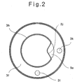
- the upper cover 3a comprises an exothermic block storing part 3e protruding at the centre in a cylindrical form to contain the exothermic unit 5 and the insulator 4, and a sensing electrode storing part 3f protruding, along the outer circumference of the exothermic block storing part 3e and also along the inner circumference of the container proper 1, in the form of a doughnut to store the sensing electrodes 11.
- Said exothermic block storing part 3e is partitioned into a cylindrical exothermic system storing part 3g for containing the exothermic system 5 and a roughly-cylindrical insulator storing part 3h for storing the insulator 4.
- an ignition apparatus storing part 3i is formed to store the ignition apparatus 6.
- the heat conversion apparatus is a pair of electrodes separately arranged to oppose each other in a container, one electrode being in the form of a needle, the other electrode being coated with an ignition agent, and the container being filled with oxygen and sealed hermetically, and the basic electric circuit of the apparatus is as shown in Fig. 7.
- the apparatus is designed to virtually convert electric energy into thermal energy and generate heat at high temperature. The details of the apparatus are as described later.
- the form of the apparatus may be designed in a desired form such as a bulb form and a diode form.
- An integrally formed apparatus may be called an ignition element or an ignition bulb (hereinafter referred to as "ignition bulb").
- ignition bulb an ignition bulb
- said insulator storing part 3h is provided with an ignition bulb support member space 3j into which an ignition bulb support member 9a of the ignition apparatus 6 is inserted.
- Said space 3j is formed in the part 3h in such a way that a portion of the insulator storing part 3h is removed and the space 3j penetrates said insulator 4.
- Said sensing electrode storing part 3f is provided, on the outer side of the ignition bulb support member space 3j, with a sensing electrode insertion hole 3k for insertion of a sensing electrode 11, and with a sensing electrode insertion hole 31 at a place angularly separated from the sensing electrode insertion hole 3k.
- said ignition apparatus comprises a piezoelectric element 7, a hammer member 8 of the pressure-exerting device, escaping electrodes 10 being the escaping discharge device, sensing electrodes 11 being the sensing device, the ignition bulb 9 being the heat conversion apparatus, etc. which are arranged and stored in a container to make a certain electric circuit shown in Fig. 5, said container comprising an upper cover 6a integrally formed of a synthetic plastic, etc. and an upper cover 6b forming a pair with said lower cover 6a.
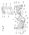
- a sensing electrode part 101 comprising one sensing electrode 11a, a hammer part 102 comprising the hammer member 8, an ignition bulb support part 103 for mounting the ignition bulb support member 9a with the ignition bulb 9, and a sensing electrode part 104 comprising the other sensing electrode 11b are electrically connected by means of metallic plate conductors 105 (illustrated by dotted line in the diagram) to form an electric circuit shown in Fig. 5, and they are integrally moulded with a synthetic resin into an electric circuit component 100.
- one sensing electrode 11a comprising one end of one conductor 105 is covered by a sensing electrode support member 101a which is made of the synthetic resin.
- the sensing electrode 11a is raised vertically by bending the conductor 105 at the root end 101b of the sensing electrode 11a.
- the electrode 11a is in contact with and is supported by a sensing electrode support piece 101c.
- one electrode 10a of the escaping electrodes 10 is formed by the conductor 105 on one side, and a contact 101d for connecting to one pole 7a of the piezoelectric element 7 is formed by the conductor 105 on the other side.
- one side of the hammer part 102 is connected to the sensing electrode part 101 through the connecting part 106.
- the root end 8a of a flat-spring-like hammer member 8 is supported by a hammer support member 102a.
- an electrode 10b is formed by one conductor 105 on one side, said electrode 10b forming a pair with said electrode 10a of the escaping electrode 10 and being separated at a certain distance from said electrode 10a.
- the conductor 105 forms a contact 103a protruding into the inner space of a fixed ring member 103b of the ignition bulb support part 103.
- the contact 103a is to be connected with a lead 9b connected to the ignition bulb 9.
- the ignition bulb support part 103 comprises the fixed ring member 103b which has a roughly triangular shape of the bottom 9c of the ignition bulb support member 9a so that the bottom 9c can be inserted into the fixed ring member 103b.
- a sensing electrode 104 is connected to one end of the ignition bulb support part 103, and the electrode 104 forms a sensing electrode 11b which is in pair with said sensing electrode 11a.
- said contact 103a protrudes into the inner space of the fixed ring member 103b, and a contact 103d of the sensing electrode 11b also protrudes into the space from the connection 103c of the sensing electrode part 104.
- the sensing electrode 11b is also covered, like the sensing electrode 11a, with a sensing electrode support member 104 which is made of the synthetic resin.
- the sensing electrode 11b is raised vertically by bending the conductor 105 at the root end 104b thereof.
- the electrode 11b is in contact with and is supported by a sensing electrode support piece 104c.
- the ignition bulb support member 9a is made of ceramic to prevent it from being melt by the heat generated at the time of ignition of the ignition bulb 9.
- a bulb mounting dent 9k is formed in the top of the ignition bulb support member 9a, and wiring holes 9e, 9e are made in the dent 9k for leads 9b, 9b of the ignition bulb 9.
- the ignition bulb 9 is, as shown in Fig. 7, a container 9f in the form of a bulb, diode, etc., preferably made of heat-resisting glass, in which electrodes 9d, 9g are arranged and oxygen is sealed up.
- a needle-like electrode wire, preferably a metal whisker 9h such as tungsten whisker is mounted towards the other electrode 9d.
- the electrode 9d is coated with an ignition agent 9j such as a powder of metal like iron, cobalt, nickel and zirconium, a powder of an alloy of such metals, or a powder of so-called pyrophoric alloy (for instance, alloys of mischmetal with iron, nickel or copper, alloys of lanthanum with magnesium, lead or tin, and vanadium-iron alloy).
- an ignition agent 9j such as a powder of metal like iron, cobalt, nickel and zirconium, a powder of an alloy of such metals, or a powder of so-called pyrophoric alloy (for instance, alloys of mischmetal with iron, nickel or copper, alloys of lanthanum with magnesium, lead or tin, and vanadium-iron alloy).
- the ignition bulb according to the present invention is configured as shown in Fig. 7, the operating voltage at the start of the discharge can be adjusted as one thinks fit by adjusting the distance between the electrodes 9d and 9h or by selecting the material of the metal whisker 9h.
- the voltage generated by the piezoelectric element, unwanted electric noises, etc. it is desirable to adjust and set the ignition bulb so that the ignition bulb is not actuated by a low voltage but a relatively high voltage.
- the electric circuit component 100 thus configured is mounted on the lower cover 6a in such a way that the sensing electrodes 101, 104 engage sensing electrode fixing pieces 6c, 6d protrudingly formed on the lower cover 6a to fix and support the electrodes 101, 104, the contact 101d of the sensing electrode 101 engages a contact fixing piece 6e for fixing and support the contact 101d, the fixed ring member 103b of the ignition bulb support part 103 engages a fixed ring member fixing piece 6f for fixing and supporting the member 103b, and the hammer part 102 engages hammer part fixing pieces 6g, 6h, respectively.
- the piezoelectric element 7 is mounted to engage piezoelectric element fixing pieces 6i formed on the lower cover 6a.
- One pole 7a of the piezoelectric element 7 is arranged to contact the contact 101d of the sensing electrode part 101.
- the other pole 7b of the piezoelectric element 7 is in electric contact under normal condition with a striker 8b formed in the hammer member 9.
- the hammer member 8 itself constitutes a part of the electric circuit.
- the bottom 9c of the ignition bulb support member 9a is inserted into the fixed ring member 103b of the ignition bulb support part 103, and the leads 9b, 9b projecting out of the bottom 9c of the ignition bulb support member 9a come to contact with the contact 103a of the hammer part 102 and the contact 103d of the sensing electrode part 104, respectively.
- the lower cover 6a is provided with an opening 6j. Around this opening 6j, a trigger member mounting projection 6k is formed. A trigger member 12 is rotatably mounted in the projection 6k.
- the piezoelectric element 7, hammer member 8, escaping electrodes 10 and sensing electrodes 11, ignition bulb 9, etc. are first mounted on the lower cover 6a.
- the sensing electrodes 11 are inserted into sensing electrode holes 61, 61 formed in the upper cover 6b, and the ignition bulb support member 9a is inserted into an ignition bulb support member hole 6m also formed in the upper cover 6b.
- the upper cover 6b is closed and mating pieces 6n, 6o, 6p, 6q formed on the lower cover 6a are mated with the mating grooves 6r, 6s, 6t, 6u made in the upper cover 6b to assemble the ignition apparatus 6 (see Fig. 6).
- the ignition bulb 9 and the sensing electrodes 11 are connected in series, and they are connected in parallel with the escaping electrodes 10, and the resulting assembly is connected to the positive and negative poles of the piezoelectric element 7 to form the electric circuit shown in Fig. 5.
- the ignition apparatus 6 thus assembled is set properly in the ignition apparatus storing part 3i of the exothermic system container 3; at the same time, the ignition bulb support member 9a is inserted into the ignition bulb support member space 3j of the exothermic system container 3, and the sensing electrodes 11a, 11b are inserted into the sensing electrode holes 3l, 3k of the sensing electrode storing part 3f, respectively.
- the sensing electrodes 11 are provided with seal rings 11c to prevent the content 3 from leaking through said sensing electrode holes 3l, 3k into the exothermic container 3 and disturbing the operation of the ignition mechanism.
- the lower cover 3b of the exothermic system container 3 is provided with the opening 3m at the centre thereof, and a shaft member 12b of the trigger member 12 of said ignition apparatus 6 is passed through the opening 3m.
- the shaft member 12b is connected to a pawl wheel 20, which is explained later, of a ratchet gear 21 on a bottom cover 16.
- the bottom cover 16 is rotatably mounted on the container proper 1.
- the ratchet gear 21 having teeth 21a formed inwardly and directed in one direction is fixed onto the bottom cover 16 by fixing members 21b.
- the pawl wheel 20 is rotatably mounted in the ratchet gear 21, with the centre of the bottom cover 16 being the axis 16.
- the pawl wheel 20 has a plurality of projecting pawls 20a, and these pawls 20a engage the teeth 21a formed on the inner circumference of the ratchet gear 21 (see Fig. 8).
- the upper part of the pawl wheel 20 is connected to the trigger member 12 via the shaft member 12b.
- the shaft member 12 may be integrally formed with the trigger member 12 or with the pawl wheel 20 in advance, and may be fit into the pawl wheel 20 or the trigger member 12 so that they have a common axis of rotation.
- the trigger member 12 and the pawl wheel 20 may be produced separately. Then they may be connected, when needed, to have a common axis of rotation. Any arrangement is acceptable provided that the rotation of the pawl wheel 20 is reliably transmitted, via the shaft member 12b, to the trigger member 12 to rotate the trigger member 12.
- the trigger member 12 is provided with a plurality of projections 12a radially arranged.
- the ratchet gear 21 will turn together with the bottom cover 16 in the direction opposite to the direction of E.
- the pawl wheel 20 and the trigger member 12 will be turned just a little by friction in the direction opposite to the direction E.
- the trigger member 12 will not be able to turn anymore since the piezoelectric element 7 is fixed onto the lower cover 6a of the ignition apparatus.
- the distance (insulation resistance) between the two sensing electrodes 11a and 11b is set much greater than the distance (insulation resistance) between the escaping discharge electrodes 10a and 10b made on the electric circuit component 100.
- the sensing electrodes 11a and 11b When the container proper 1 is filled with a content 2 which comprises a material or materials having a fairly high conductivity relative to air, such as water, fluid of which main component is water, or a mixture of water or the fluid and a solid, the sensing electrodes 11a and 11b will be energized through the content 2, and when the ignition operation is made, the spark discharge will be generated between the electrodes of the ignition bulb 9 having the smallest insulation resistance. At the same time, the ignition agent 9j coated over the electrode 9d will be ignited, and a temperature as high almost 1000°C will be generated instantly. As a result, the exothermic system 5 will be ignited to start heat generation.
- a content 2 which comprises a material or materials having a fairly high conductivity relative to air, such as water, fluid of which main component is water, or a mixture of water or the fluid and a solid
- the sensing electrodes 11a and 11b When the ignition operation is made, the spark discharge will be generated between the electrodes of the ignition bulb 9
- the exothermic system 5 may be improved in its ignition performance, heat efficiency and heating speed by selecting, as one thinks fit, an oxidizing agent comprising metal oxides such as iron oxide, copper oxide and lead oxide, and a combustible material comprising metals such as titanium and iron or semi-metals such as silicon, said metals and semi-metals of the combustible material having a grater heat of oxidation than the metals of the oxidizing agent.
- an oxidizing agent comprising metal oxides such as iron oxide, copper oxide and lead oxide
- a combustible material comprising metals such as titanium and iron or semi-metals such as silicon
- the insulator 4 it is sufficient to select an insulator which effectively adsorbs the smell and gas generated slightly during the ignition and heat generation.
- zeolite is appropriate.
- Fig. 9 shows one embodiment of the ignition apparatus 30 according to the present invention.
- the apparatus 30 basically has a configuration and an electric circuit both similar to those of the heating mechanism of the container having a heating function shown in Fig. 1.
- This ignition apparatus 30 differs from that of Fig. 1 in the following point:
- the insulator 4 is extended over sensing electrodes 11' so that the sensing electrodes 11' penetrate through a part of the insulator 4 and the sensing electrodes 11' are exposed on the exterior of the ignition apparatus 30, and seal packings 23 are provided for hermetic sealing.
- This ignition apparatus therefore, may provide a convenient ignition apparatus which can be removably connected to a separate container filled with a liquid material to be heated such as stew to heat the separate container as one thinks fit.
- a voltage as high as several thousands of volts is generated across both the ends of the piezoelectric element by striking the piezoelectric element with the hammer member provided in the container with a heating function.
- the container with a heating function is not filled with a liquid content, the gap between the sensing electrodes is large and it is hard to discharge across them. Hence the circuit including the ignition bulb is virtually disconnected.
- spark discharge will be generated only across the gap between the escaping discharge electrodes which are well separated from the exothermic system and are easy to discharge between them. No spark discharge will be generated between the electrodes of the ignition bulb, and ignition of the exothermic system will be avoided.
- the container with a heating function when the container with a heating function is filled with a material to be heated having a high conductivity compared to air, such material being water or fluid having water as the main component or a mixture of water or the fluid and a solid, electricity will be conducted across the sensing electrodes 11 through the liquid content present between the gap of the sensing electrodes 11a and 11b; thus the parallel circuit of Fig. 5 is closed.
- a high voltage when a high voltage is generated between both the ends of the piezoelectric element, spark discharge will be generated between the ignition bulb electrodes rather than between the escaping discharge electrodes since the gap between the ignition bulb electrodes is smaller than that of the escaping discharge electrodes (i.e. the electric resistance of the ignition bulb electrodes is smaller).
- the ignition agent coated over the electrode will be ignited, and a high temperature will be produced instantly. As a result, the exothermic system will be ignited to generate heat, and this heat will heat up the content.
- the container with a heating function when the container with a heating function is not filled with a liquid content, when the desired content is not present, or the container is filled with only a dry material, an inadvertent ignition operation will not ignite the exothermic system to generate heat.
- the container is arranged to heat the content only when the container is filled with a proper content in a proper quantity.
- the heat conversion apparatus uses the ignition bulb which is made by separately arranging a pair of electrodes to oppose each other in a container and filling and sealing up the container with oxygen. Hence the electric energy is instantly converted into thermal energy, and the heat can be generated at a high temperature. Moreover, to prevent wrong operation or inadvertent discharge from starting heat generation, the heat conversion apparatus can be made not to be actuated by a low temperature but a relatively high temperature by adjusting, for example, the electrodes. Thus the heat conversion apparatus can provide an extremely safe and highly reliable heat conversion apparatus for ignition. Furthermore, its production can be simplified, and a reduction in cost can be realized by mass production. It is most appropriate to use the heat conversion apparatus in the above-mentioned container with a heating function or the ignition apparatus according to the present invention.
- the ignition apparatus in which the heat conversion apparatus is integrated does not require any complicated electric circuit for stabilizing and reducing electric pulses. Hence a simple and compact ignition apparatus can be provided. Since the heat conversion apparatus has a characteristic that it is not actuated by a relatively low voltage but a high voltage, even one makes a wrong ignition operation, spark discharge due to electrostatic induction, electromagnetic induction, leakage or radiation of current will not be generated between the ignition discharge electrodes. Thus the ignition apparatus provides an ignition apparatus which is free of so-called wrong operation.
- the hammer part of the pressure-exerting device, the escaping discharge device, and the sensing device are integrally formed together with conductors in a synthetic resin into an electric circuit component.
- Most of the members comprising the electric circuit of the ignition apparatus are thus formed into one unit member. In this way, the ignition apparatus production process can be simplified into simple steps of operation such as insertion of the piezoelectric element and insertion of the heat conversion apparatus. This, in turn, improves the production efficiency and mostly eliminates errors from the production, and reduces the product cost.
- the various components of the ignition apparatus members other than the heat conversion apparatus including the ignition bulb are assembled in advance into a single unit, and the heat conversion apparatus is removably inserted into and connected with the unit. Since the heat conversion apparatus is a relatively delicate member, this arrangement makes it easy to handle the heat conversion apparatus in the production process. The arrangement also helps to prevent occurrence of a defective member, and also significantly simplifies replacement or repair of any defective member. Thus efficient and economic production will be accomplished.
- the container with a heating function having the ignition apparatus with said heat conversion apparatus will not ignite to generate heat when the heated container is not filled with a content, when the heated container is filled with only a dry content, or when the container is not filled with the desired content.
- the invention thus provides the container with a heating function which is able to ignite to generate heat only when the container is filled with water or a fluid of which main component is water, or a mixture of water or the fluid and a solid. Accordingly, the present invention easily and inexpensively provides an extremely safe and convenient container with a heating function, which can be reliably ignited to generate heat by a much easier operation than before and will not be ignited by wrong operation or vibration during transportation, etc.
Landscapes
- Engineering & Computer Science (AREA)
- Chemical & Material Sciences (AREA)
- Combustion & Propulsion (AREA)
- Mechanical Engineering (AREA)
- General Engineering & Computer Science (AREA)
- Food Science & Technology (AREA)
- Physics & Mathematics (AREA)
- Thermal Sciences (AREA)
- Chemical Kinetics & Catalysis (AREA)
- Cookers (AREA)
- Yarns And Mechanical Finishing Of Yarns Or Ropes (AREA)
- Resistance Heating (AREA)
- Catching Or Destruction (AREA)
- Air Bags (AREA)
- Road Repair (AREA)
- Control Of Resistance Heating (AREA)
- Ignition Installations For Internal Combustion Engines (AREA)
Abstract
Description
- This invention relates to a heat conversion apparatus which virtually converts electric energy into thermal energy and generates heat at high temperature, an ignition apparatus for igniting an exothermic system to generate heat from thereof and having a (safety) mechanism for avoiding ignition, and a container with a heating function having said ignition apparatus.
- Heated containers have been with us for some years, which utilize heat generated by the self-combustion of an exothermic agent comprising an oxygen feeder and a combustible material. For instance, there are Utility Model Publication No. SHO-62-146427 and Utility Model Publication No. SHO-63-42089. In these heated containers, the exothermic agent is ignited by means of a safety fuse or a filament type electric heater connected to the exothermic agent.
- These heated containers, however, are very inconvenient to use because an igniter, such as match, lighter, and a battery for operating the filament type electric heater, is separately needed. In particular, when the exothermic agent is arranged to be ignited by means of a safety fuse, there are problems of the difficulty of use of the heated container outdoors, in rainy weather or in strong wind.
- To solve the above-mentioned problems of the prior art and to improve the ignition performance, heat efficiency, and heating speed, the present inventors, et al have already proposed a variety of heated containers in which the exothermic system comprises an exothermic agent, an ignition agent arranged close to the exothermic agent and more easy to ignite than the exothermic agent, and an ignition part arranged close to the ignition agent.
- For instance, in the Patent Application No. HEI-2-132332 of the present inventors, et al, we proposed a container with a heating function, which is provided with a piezoelectric element for receiving a pressure from force such as striking force to generate electricity, a hammer member for striking the piezoelectric element, a sensing device for sensing whether the container is filled with water or fluid of which main component is water, ignition discharge electrodes for discharging electricity, and escaping discharge electrodes.
- This container with a heating function, however, involved a risk of heat generation due to wrong operation. A high voltage generated by the piezoelectric element may generate unwanted electric noises due to electrostatic induction, electromagnetic induction, leakage of current, radiation, etc. As a result, even when the circuit between the sensing electrodes is not closed, a voltage may be applied across the ignition discharge electrodes, and if the voltage is excessively large, even when the container is not filled with the material to be heated, the ignition operation may cause a spark discharge across the ignition discharge electrodes to ignite the exothermic system.
- To solve this problem, the present inventors et al proposed a container with a heating function, in which the voltage generated by the piezoelectric element was reduced to eliminate the escaping discharge electrodes, and moreover, an electric circuit was provided to stabilize the electric pulses and reduce unwanted electric pulses so as to prevent ignition by wrong operation. Furthermore, we proposed a bulb (Patent Application No. HEI-2-277039) as a heat conversion apparatus which virtually converts electric energy into thermal energy and generates heat at high temperature for use in the above-mentioned container with a heating function. The bulb can be operated at a low voltage and has the following configuration: A thin metallic wire is sealed up in a container with oxygen, and a pair of separated electrodes are provided in the container. The surfaces of the electrodes are coated with an ignition agent which is an insulator or a resistor of high resistance.
- In this case, however, an extra electric circuit was required for stabilizing and reducing the electric pulses. The configuration of the circuit was complex, and the production process thereof was also complex and the cost was higher since expensive electronic components were used. On the other hand, it was necessary to seal metallic thin wire, etc. in the bulb used as the heat conversion apparatus, and the production process was complex, resulting in a higher cost.
- In view of the above mentioned problems, one object of the present invention is to provide a container with a heating function, which requires no complicated electric circuit for stabilizing and reducing electric pulses and is free of any possibility of heat generation due to wrong operation wherein a wrong ignition operation actuates the heat conversion apparatus to ignite the exothermic system.
- Another object of the present invention is to provide a compact ignition apparatus of a simple construction, which requires no complicated electric circuit for stabilizing and reducing electric pulses and is free of any possibility of wrong operation wherein a wrong ignition operation actuates the heat conversion apparatus to ignite the exothermic system.
- Another object of the present invention is to provide a heat conversion apparatus which is not actuated by a low voltage but a relatively high voltage and is applicable for said container with a heating function or ignition apparatus.
- The present invention was invented in view of the above-mentioned problems and objectives, and is a heat conversion apparatus which virtually converts electric energy into thermal energy and generates heat at high temperature, said heat conversion apparatus being characterized in that the apparatus comprises a pair of electrodes separately arranged to oppose each other in a container, one electrode being in the form of a needle, the other electrode being coated with an ignition agent, and the container being filled with oxygen and sealed up so that, when a spark discharge is generated between the electrodes, the ignition agent is ignited.
- The present invention is also an ignition apparatus for igniting an exothermic system, said ignition apparatus being characterized in that said ignition apparatus comprises a piezoelectric element for receiving a pressure from force such as striking force to generate electricity, a pressure-exerting device for applying pressure to the piezoelectric element, a sensing device for sensing whether the container for containing a desired material to be heated is filled with the material to be heated, said heat conversion apparatus which virtually converts electric energy into thermal energy and generates heat at high temperature when said sensing device detects that the container is filled with said desired material to be heated, and an escaping discharge device for discharging the electricity generated by said piezoelectric element at a place well away from the exothermic system when said sensing device does not sense that the container is filled with the desired material to be heated, and that said piezoelectric element, sensing device, heat conversion apparatus and escaping discharge device are mutually and electrically connected.
- Furthermore, the present invention is a container with a heating function characterized in that the container is provided with an exothermic system for heating a material to be heated, and said ignition apparatus for igniting said exothermic system to release heat, said material to be heated being contained in the container and consisting of water or a fluid of which main component is water, or a mixture of water or the fluid and solid.
- In the following, one embodiment of the invention will now be described, by way of example, with reference to the attached drawings, in which:
- Figure 1 is a longitudinal sectional view of one embodiment of a container with a heating function according to the present invention;
- Figure 2 is a sectional view along the line A-A of Figure 1;
- Figure 3 is an exploded view of an ignition apparatus according to the present invention;
- Figure 4 is a perspective view showing an electric circuit component of the ignition apparatus according to the present invention;
- Figure 5 is an electric circuit diagram of the ignition apparatus according to the present invention;
- Figure 6 is a perspective view showing the assembled state of the ignition apparatus according to the present invention;
- Figure 7 is a schematic diagram showing a heat conversion apparatus according to the present invention;
- Figure 8 is a sectional view along the line B-B of Figure 1; and
- Figure 9 is a longitudinal sectional view showing the ignition apparatus according to the present invention.
- As shown in Fig. 1, a roughly-cylindrical container proper 1 made of metal, preferably of steel, is provided, in the lower part thereof, with an
exothermic system container 3 also made of metal. Theexothermic system container 3 comprises anupper cover 3a also functioning as the bottom cover of the container proper 1 and alower cover 3b, and as described later, anexothermic system 5, aninsulator 4, and anignition apparatus 6 are contained inside theexothermic system container 3. - The entire outer circumference 3c of the
upper cover 3a and the entireouter circumference 3d of thelower cover 3b are hermetically sealed and fixed to the lower end 1a of the container proper 1 so that thecontent 2 contained in the container proper 1 does not leak out of thecontainer 1. Theupper cover 3a comprises an exothermicblock storing part 3e protruding at the centre in a cylindrical form to contain theexothermic unit 5 and theinsulator 4, and a sensingelectrode storing part 3f protruding, along the outer circumference of the exothermicblock storing part 3e and also along the inner circumference of the container proper 1, in the form of a doughnut to store thesensing electrodes 11. Said exothermicblock storing part 3e is partitioned into a cylindrical exothermicsystem storing part 3g for containing theexothermic system 5 and a roughly-cylindricalinsulator storing part 3h for storing theinsulator 4. Beneath said exothermicblock storing part 3e and sensingelectrode storing part 3f, an ignitionapparatus storing part 3i is formed to store theignition apparatus 6. - The heat conversion apparatus according to the present invention is a pair of electrodes separately arranged to oppose each other in a container, one electrode being in the form of a needle, the other electrode being coated with an ignition agent, and the container being filled with oxygen and sealed hermetically, and the basic electric circuit of the apparatus is as shown in Fig. 7. The apparatus is designed to virtually convert electric energy into thermal energy and generate heat at high temperature. The details of the apparatus are as described later. The form of the apparatus may be designed in a desired form such as a bulb form and a diode form. An integrally formed apparatus may be called an ignition element or an ignition bulb (hereinafter referred to as "ignition bulb"). To assure the reliable connection of the lead wires to the circuit and to reliably hold the ignition bulb, it is desirable to mount the ignition bulb in an ignition bulb holding member and use them as a set.
- As shown in Fig. 2, said
insulator storing part 3h is provided with an ignition bulbsupport member space 3j into which an ignitionbulb support member 9a of theignition apparatus 6 is inserted.Said space 3j is formed in thepart 3h in such a way that a portion of theinsulator storing part 3h is removed and thespace 3j penetrates saidinsulator 4. Said sensingelectrode storing part 3f is provided, on the outer side of the ignition bulbsupport member space 3j, with a sensingelectrode insertion hole 3k for insertion of asensing electrode 11, and with a sensingelectrode insertion hole 31 at a place angularly separated from the sensingelectrode insertion hole 3k. - Moreover, as explained later, in the centre of the
lower cover 3b of saidexothermic system container 3, is provided an opening 3m for a drive shaft which rotates to drive atrigger member 12 for actuating the ignition mechanism of theignition apparatus 6. - As shown in Fig. 3, said ignition apparatus comprises a
piezoelectric element 7, ahammer member 8 of the pressure-exerting device, escapingelectrodes 10 being the escaping discharge device, sensingelectrodes 11 being the sensing device, theignition bulb 9 being the heat conversion apparatus, etc. which are arranged and stored in a container to make a certain electric circuit shown in Fig. 5, said container comprising anupper cover 6a integrally formed of a synthetic plastic, etc. and anupper cover 6b forming a pair with saidlower cover 6a. - To be more specific, as shown in Fig. 4, a
sensing electrode part 101 comprising onesensing electrode 11a, ahammer part 102 comprising thehammer member 8, an ignitionbulb support part 103 for mounting the ignitionbulb support member 9a with theignition bulb 9, and asensing electrode part 104 comprising theother sensing electrode 11b are electrically connected by means of metallic plate conductors 105 (illustrated by dotted line in the diagram) to form an electric circuit shown in Fig. 5, and they are integrally moulded with a synthetic resin into anelectric circuit component 100. - In the
sensing electrode part 101, onesensing electrode 11a comprising one end of oneconductor 105 is covered by a sensingelectrode support member 101a which is made of the synthetic resin. Thesensing electrode 11a is raised vertically by bending theconductor 105 at theroot end 101b of thesensing electrode 11a. Theelectrode 11a is in contact with and is supported by a sensingelectrode support piece 101c. At the root end of thesensing electrode 11a, oneelectrode 10a of the escapingelectrodes 10 is formed by theconductor 105 on one side, and acontact 101d for connecting to onepole 7a of thepiezoelectric element 7 is formed by theconductor 105 on the other side. - On the other hand, one side of the
hammer part 102 is connected to thesensing electrode part 101 through the connectingpart 106. Theroot end 8a of a flat-spring-like hammer member 8 is supported by ahammer support member 102a. At theroot end 8a of thehammer member 8, anelectrode 10b is formed by oneconductor 105 on one side, saidelectrode 10b forming a pair with saidelectrode 10a of the escapingelectrode 10 and being separated at a certain distance from saidelectrode 10a. On the other side of theroot end 8a, theconductor 105 forms acontact 103a protruding into the inner space of a fixedring member 103b of the ignitionbulb support part 103. Thecontact 103a is to be connected with alead 9b connected to theignition bulb 9. - The ignition
bulb support part 103 comprises the fixedring member 103b which has a roughly triangular shape of the bottom 9c of the ignitionbulb support member 9a so that the bottom 9c can be inserted into the fixedring member 103b. Asensing electrode 104 is connected to one end of the ignitionbulb support part 103, and theelectrode 104 forms asensing electrode 11b which is in pair with saidsensing electrode 11a. As for the fixedring member 103b, saidcontact 103a protrudes into the inner space of the fixedring member 103b, and acontact 103d of thesensing electrode 11b also protrudes into the space from theconnection 103c of thesensing electrode part 104. Thesensing electrode 11b is also covered, like thesensing electrode 11a, with a sensingelectrode support member 104 which is made of the synthetic resin. Thesensing electrode 11b is raised vertically by bending theconductor 105 at theroot end 104b thereof. Theelectrode 11b is in contact with and is supported by a sensingelectrode support piece 104c. - The ignition
bulb support member 9a is made of ceramic to prevent it from being melt by the heat generated at the time of ignition of theignition bulb 9. Abulb mounting dent 9k is formed in the top of the ignitionbulb support member 9a, andwiring holes dent 9k forleads ignition bulb 9. Theignition bulb 9 is, as shown in Fig. 7, acontainer 9f in the form of a bulb, diode, etc., preferably made of heat-resisting glass, in whichelectrodes electrode 9g, a needle-like electrode wire, preferably ametal whisker 9h such as tungsten whisker is mounted towards theother electrode 9d. Theelectrode 9d is coated with anignition agent 9j such as a powder of metal like iron, cobalt, nickel and zirconium, a powder of an alloy of such metals, or a powder of so-called pyrophoric alloy (for instance, alloys of mischmetal with iron, nickel or copper, alloys of lanthanum with magnesium, lead or tin, and vanadium-iron alloy). As a result, when a spark discharge is generated between theelectrodes ignition agent 9j at the top end of theelectrode 9d will be ignited. This, in turn, with the help of the oxygen filled in the ignition bulb, will cause rapid combustion and generate heat at high temperature. Theignition bulb container 9f will be instantly ruptured to release heat energy at very high temperature. Since theignition bulb 9 is set almost in contact with the bottom of theexothermic system 5, the thermal energy at high temperature of theignition bulb 9 will be directly used as the ignition energy for theexothermic system 5. Thus ignition of theexothermic system 5 can be made easily and reliably. - Moreover, since the ignition bulb according to the present invention is configured as shown in Fig. 7, the operating voltage at the start of the discharge can be adjusted as one thinks fit by adjusting the distance between the
electrodes metal whisker 9h. In the present invention, in consideration of the strength of thehammer member 8, the voltage generated by the piezoelectric element, unwanted electric noises, etc., it is desirable to adjust and set the ignition bulb so that the ignition bulb is not actuated by a low voltage but a relatively high voltage. - The
electric circuit component 100 thus configured is mounted on thelower cover 6a in such a way that thesensing electrodes electrode fixing pieces lower cover 6a to fix and support theelectrodes contact 101d of thesensing electrode 101 engages acontact fixing piece 6e for fixing and support thecontact 101d, the fixedring member 103b of the ignitionbulb support part 103 engages a fixed ringmember fixing piece 6f for fixing and supporting themember 103b, and thehammer part 102 engages hammerpart fixing pieces - The
piezoelectric element 7 is mounted to engage piezoelectricelement fixing pieces 6i formed on thelower cover 6a. Onepole 7a of thepiezoelectric element 7 is arranged to contact thecontact 101d of thesensing electrode part 101. On the other hand, theother pole 7b of thepiezoelectric element 7 is in electric contact under normal condition with astriker 8b formed in thehammer member 9. Thehammer member 8 itself constitutes a part of the electric circuit. - The bottom 9c of the ignition
bulb support member 9a is inserted into the fixedring member 103b of the ignitionbulb support part 103, and theleads bulb support member 9a come to contact with thecontact 103a of thehammer part 102 and thecontact 103d of thesensing electrode part 104, respectively. Thelower cover 6a is provided with anopening 6j. Around thisopening 6j, a triggermember mounting projection 6k is formed. Atrigger member 12 is rotatably mounted in theprojection 6k. - Thus the
piezoelectric element 7,hammer member 8, escapingelectrodes 10 andsensing electrodes 11,ignition bulb 9, etc. are first mounted on thelower cover 6a. After that, thesensing electrodes 11 are inserted into sensing electrode holes 61, 61 formed in theupper cover 6b, and the ignitionbulb support member 9a is inserted into an ignition bulbsupport member hole 6m also formed in theupper cover 6b. Then theupper cover 6b is closed andmating pieces lower cover 6a are mated with themating grooves upper cover 6b to assemble the ignition apparatus 6 (see Fig. 6). - When arranged as described above, the
ignition bulb 9 and thesensing electrodes 11 are connected in series, and they are connected in parallel with the escapingelectrodes 10, and the resulting assembly is connected to the positive and negative poles of thepiezoelectric element 7 to form the electric circuit shown in Fig. 5. - The
ignition apparatus 6 thus assembled is set properly in the ignitionapparatus storing part 3i of theexothermic system container 3; at the same time, the ignitionbulb support member 9a is inserted into the ignition bulbsupport member space 3j of theexothermic system container 3, and thesensing electrodes sensing electrode holes 3l, 3k of the sensingelectrode storing part 3f, respectively. Thesensing electrodes 11 are provided withseal rings 11c to prevent thecontent 3 from leaking through saidsensing electrode holes 3l, 3k into theexothermic container 3 and disturbing the operation of the ignition mechanism. - The
lower cover 3b of theexothermic system container 3 is provided with theopening 3m at the centre thereof, and ashaft member 12b of thetrigger member 12 of saidignition apparatus 6 is passed through theopening 3m. Theshaft member 12b is connected to apawl wheel 20, which is explained later, of aratchet gear 21 on abottom cover 16. - As shown in Fig. 1 and Fig. 9, at the bottom of the container proper 1, the
bottom cover 16 is rotatably mounted on the container proper 1. At the centre of thebottom cover 16, theratchet gear 21 havingteeth 21a formed inwardly and directed in one direction is fixed onto thebottom cover 16 by fixingmembers 21b. Thepawl wheel 20 is rotatably mounted in theratchet gear 21, with the centre of thebottom cover 16 being theaxis 16. Thepawl wheel 20 has a plurality of projectingpawls 20a, and thesepawls 20a engage theteeth 21a formed on the inner circumference of the ratchet gear 21 (see Fig. 8). - The upper part of the
pawl wheel 20 is connected to thetrigger member 12 via theshaft member 12b. Theshaft member 12 may be integrally formed with thetrigger member 12 or with thepawl wheel 20 in advance, and may be fit into thepawl wheel 20 or thetrigger member 12 so that they have a common axis of rotation. Alternatively, thetrigger member 12 and thepawl wheel 20 may be produced separately. Then they may be connected, when needed, to have a common axis of rotation. Any arrangement is acceptable provided that the rotation of thepawl wheel 20 is reliably transmitted, via theshaft member 12b, to thetrigger member 12 to rotate thetrigger member 12. Thetrigger member 12 is provided with a plurality ofprojections 12a radially arranged. When thetrigger member 12 is turned, oneprojection 12a engages theend 8c of thehammer member 8 at a time (see Fig. 3). These members are made of an insulating material such as synthetic resin so that the electricity from thepiezoelectric element 7 is not conducted through. - With this configuration, to ignite, one turns the
bottom cover 16 counterclockwise as indicated by an arrow E of Fig. 8. Theratchet gear 21 turns together with thebottom cover 16 in the direction of E, and theteeth 21a formed on the inner circumference of theratchet gear 21 engage a plurality ofpawls 20a protrudingly formed on the pawl wheel 20 (see Fig. 8). As a result, thepawl wheel 20 also turns in the direction of E, and thetrigger member 12 connected to thepawl wheel 20 turns to the same direction. Moreover, together with the rotation of thetrigger member 12, one of theprojections 12a on thetrigger member 12 will engage theend 8c of thehammer member 8, bending thehammer member 8 away from thepiezoelectric element 7. When thebottom cover 16 is rotated further, the engagement between theprojection 12a of thetrigger member 12 and theend 8c of thehammer member 8 will be released. Thehammer member 8 will be moved by the elastic force of thehammer member 8 being a leaf spring to strike oneend 7b of thepiezoelectric element 7 and generate a voltage across both the ends of thepiezoelectric element 7. Ignition, therefore, can be easily done by simply turning the bottom cover. - On the other hand, if the
bottom cover 16 is rotated in the direction opposite to the direction of the arrow E or clockwise as seen in Fig. 8, theratchet gear 21 will turn together with thebottom cover 16 in the direction opposite to the direction of E. At the same time, thepawl wheel 20 and thetrigger member 12 will be turned just a little by friction in the direction opposite to the direction E. However, when one of theprojections 12a of thetrigger member 12 engage theend 8c of thehammer member 8 to force thehammer member 8 towards and against thepiezoelectric element 7, thetrigger member 12 will not be able to turn anymore since thepiezoelectric element 7 is fixed onto thelower cover 6a of the ignition apparatus. If thebottom cover 16 is rotated further clockwise, thepawls 20a of thepawl wheel 20 will be bent and released from the engagement with theteeth 21a of theratchet gear 21. Then thepawl wheel 20 will not turn anymore, and theratchet gear 21 will run idle and the rotation of thebottom cover 16 will not be transmitted to the trigger member 12 (see Fig. 8). Accordingly, even if thebottom cover 16 is rotated in the wrong direction, no excessive forces will not be exerted to thetrigger member 12,hammer member 8,piezoelectric element 7 and their fixing parts. In this way, inadvertent ignition, for example, due to vibration, etc. during transportation of the container, can be avoided, and any damage due to wrong operation can be prevented. - Furthermore, as shown in Fig. 4, the distance (insulation resistance) between the two
sensing electrodes discharge electrodes electric circuit component 100. - With this arrangement, when the container proper 1 is not filled with a
content 2, when a desiredcontent 2 is not present in the container proper 1, or when the container proper 1 is filled with only dry material, if the ignition operation is made, spark discharge will be generated only between the escapingdischarge electrodes ignition bulb 9 will not be energized. Hence theexothermic system 5 will never be ignited. - When the container proper 1 is filled with a
content 2 which comprises a material or materials having a fairly high conductivity relative to air, such as water, fluid of which main component is water, or a mixture of water or the fluid and a solid, thesensing electrodes content 2, and when the ignition operation is made, the spark discharge will be generated between the electrodes of theignition bulb 9 having the smallest insulation resistance. At the same time, theignition agent 9j coated over theelectrode 9d will be ignited, and a temperature as high almost 1000°C will be generated instantly. As a result, theexothermic system 5 will be ignited to start heat generation. - As disclosed in the Patent Publication No. HEI-2-7918 and the Patent Publication No. HEI-1-288218, the
exothermic system 5 may be improved in its ignition performance, heat efficiency and heating speed by selecting, as one thinks fit, an oxidizing agent comprising metal oxides such as iron oxide, copper oxide and lead oxide, and a combustible material comprising metals such as titanium and iron or semi-metals such as silicon, said metals and semi-metals of the combustible material having a grater heat of oxidation than the metals of the oxidizing agent. - As for the
insulator 4, it is sufficient to select an insulator which effectively adsorbs the smell and gas generated slightly during the ignition and heat generation. For instance, zeolite is appropriate. - Fig. 9 shows one embodiment of the
ignition apparatus 30 according to the present invention. Theapparatus 30 basically has a configuration and an electric circuit both similar to those of the heating mechanism of the container having a heating function shown in Fig. 1. Thisignition apparatus 30 differs from that of Fig. 1 in the following point: Theinsulator 4 is extended over sensing electrodes 11' so that the sensing electrodes 11' penetrate through a part of theinsulator 4 and the sensing electrodes 11' are exposed on the exterior of theignition apparatus 30, and seal packings 23 are provided for hermetic sealing. This ignition apparatus, therefore, may provide a convenient ignition apparatus which can be removably connected to a separate container filled with a liquid material to be heated such as stew to heat the separate container as one thinks fit. - The above-mentioned embodiment is just a preferred embodiment of the present invention, and unnecessary restrictions should not be derived from it since persons skilled in the art can easily make changes and modifications. The scope of the present invention should be limited by only the claims.
- According to the present invention, a voltage as high as several thousands of volts is generated across both the ends of the piezoelectric element by striking the piezoelectric element with the hammer member provided in the container with a heating function. When the container with a heating function is not filled with a liquid content, the gap between the sensing electrodes is large and it is hard to discharge across them. Hence the circuit including the ignition bulb is virtually disconnected. As a result, spark discharge will be generated only across the gap between the escaping discharge electrodes which are well separated from the exothermic system and are easy to discharge between them. No spark discharge will be generated between the electrodes of the ignition bulb, and ignition of the exothermic system will be avoided.
- On the other hand, when the container with a heating function is filled with a material to be heated having a high conductivity compared to air, such material being water or fluid having water as the main component or a mixture of water or the fluid and a solid, electricity will be conducted across the
sensing electrodes 11 through the liquid content present between the gap of thesensing electrodes - According to the present invention, when the container with a heating function is not filled with a liquid content, when the desired content is not present, or the container is filled with only a dry material, an inadvertent ignition operation will not ignite the exothermic system to generate heat. The container is arranged to heat the content only when the container is filled with a proper content in a proper quantity.
- The heat conversion apparatus according to the present invention uses the ignition bulb which is made by separately arranging a pair of electrodes to oppose each other in a container and filling and sealing up the container with oxygen. Hence the electric energy is instantly converted into thermal energy, and the heat can be generated at a high temperature. Moreover, to prevent wrong operation or inadvertent discharge from starting heat generation, the heat conversion apparatus can be made not to be actuated by a low temperature but a relatively high temperature by adjusting, for example, the electrodes. Thus the heat conversion apparatus can provide an extremely safe and highly reliable heat conversion apparatus for ignition. Furthermore, its production can be simplified, and a reduction in cost can be realized by mass production. It is most appropriate to use the heat conversion apparatus in the above-mentioned container with a heating function or the ignition apparatus according to the present invention.
- The ignition apparatus in which the heat conversion apparatus is integrated does not require any complicated electric circuit for stabilizing and reducing electric pulses. Hence a simple and compact ignition apparatus can be provided. Since the heat conversion apparatus has a characteristic that it is not actuated by a relatively low voltage but a high voltage, even one makes a wrong ignition operation, spark discharge due to electrostatic induction, electromagnetic induction, leakage or radiation of current will not be generated between the ignition discharge electrodes. Thus the ignition apparatus provides an ignition apparatus which is free of so-called wrong operation.
- Further, the hammer part of the pressure-exerting device, the escaping discharge device, and the sensing device are integrally formed together with conductors in a synthetic resin into an electric circuit component. Most of the members comprising the electric circuit of the ignition apparatus are thus formed into one unit member. In this way, the ignition apparatus production process can be simplified into simple steps of operation such as insertion of the piezoelectric element and insertion of the heat conversion apparatus. This, in turn, improves the production efficiency and mostly eliminates errors from the production, and reduces the product cost.
- Of the various components of the ignition apparatus, members other than the heat conversion apparatus including the ignition bulb are assembled in advance into a single unit, and the heat conversion apparatus is removably inserted into and connected with the unit. Since the heat conversion apparatus is a relatively delicate member, this arrangement makes it easy to handle the heat conversion apparatus in the production process. The arrangement also helps to prevent occurrence of a defective member, and also significantly simplifies replacement or repair of any defective member. Thus efficient and economic production will be accomplished.
- The container with a heating function having the ignition apparatus with said heat conversion apparatus will not ignite to generate heat when the heated container is not filled with a content, when the heated container is filled with only a dry content, or when the container is not filled with the desired content. The invention thus provides the container with a heating function which is able to ignite to generate heat only when the container is filled with water or a fluid of which main component is water, or a mixture of water or the fluid and a solid. Accordingly, the present invention easily and inexpensively provides an extremely safe and convenient container with a heating function, which can be reliably ignited to generate heat by a much easier operation than before and will not be ignited by wrong operation or vibration during transportation, etc.
Claims (9)
- A heat conversion apparatus (9) which virtually converts electric energy into thermal energy and generates heat at high temperature,
said heat conversion apparatus being characterized in that the apparatus comprises a pair of electrodes (9d, 9g) separately arranged to oppose each other in a container (9f), one electrode (9g) being in the form of a needle, the other electrode (9d) being coated with an ignition agent (9j), and the container (9f) being filled with oxygen and sealed up so that, when a spark discharge is generated between the electrodes, the ignition agent is ignited. - A heat conversion apparatus of Claim 1 characterized in that said ignition agent (9j) is a resistor of high resistance.
- An ignition apparatus for igniting an exothermic system,
said ignition apparatus being characterized in that said ignition apparatus comprises
a piezoelectric element (7) for receiving a pressure from force such as striking force to generate electricity,
a pressure-exerting (8) device for applying pressure to the piezoelectric element,
a sensing device (11) for sensing whether the container for containing a desired material to be heated is filled with the material to be heated,
the heat conversion apparatus (9) of Claim 1 or Claim 2, which virtually converts electric energy into thermal energy and generates heat at high temperature when said sensing device detects that the container is filled with said desired material to be heated, and
an escaping discharge device (10) for discharging the electricity generated by said piezoelectric element at a place well away from the exothermic system when said sensing device does not sense that the container is filled with the desired material to be heated, and
that said piezoelectric element, sensing device, heat conversion apparatus and escaping discharge device are mutually and electrically connected. - The ignition apparatus of Claim 3 characterized in that said heat conversion apparatus (9) and said sensing device (11) are connected in series, and these and said escaping discharge (10) device are connected in parallel to the positive and negative electrodes of said piezoelectric element to make an electric circuit.
- The ignition apparatus of Claim 3 or Claim 4 characterized in that the apparatus is arranged so that the difficulty to discharge in the descending order is said heat conversion apparatus (9), said escaping discharge device (10), and said sensing device (11).
- The ignition apparatus of any one of Claim 3 through Claim 5 characterized in that said piezoelectric element (7), pressure-exerting device (8), heat conversion apparatus (9), escaping discharge device (10) and sensing device (11) are arranged and connected in an integrally moulded moulding member.
- An ignition apparatus of any one of Claim 3 through Claim 5 characterized in that said piezoelectric element (7), pressure-exerting device (8), escaping discharge device (10) and sensing device (11) are arranged and connected in an integrally moulded moulding member to form a unit, and a removable heat conversion apparatus is fit into or connected to said unit.
- The ignition apparatus of any one of Claim 3 through Claim 7 characterized in that a hammer part of the pressure-exerting device (8), the escaping discharge device (10) and the sensing device (11) are integrally moulded, together with conductors, in a synthetic resin to form an electric circuit component, and said piezoelectric element (7) and heat conversion apparatus (9) are removably and electrically connected to the electric circuit component.
- A container with a heating function characterized in that the container is provided with an exothermic system (3) for heating a material (2) to be heated, and an ignition apparatus described in any one of Claim 3 through Claim 8 for igniting said exothermic system to release heat, said material (2) to be heated being contained in the container and consisting of water or a fluid of which main component is water, or a mixture of water or the fluid and solid.
Applications Claiming Priority (2)
| Application Number | Priority Date | Filing Date | Title |
|---|---|---|---|
| JP4028541A JP2851471B2 (en) | 1992-02-14 | 1992-02-14 | Ignition / heating mechanism |
| JP28541/92 | 1992-02-14 |
Publications (2)
| Publication Number | Publication Date |
|---|---|
| EP0555990A1 EP0555990A1 (en) | 1993-08-18 |
| EP0555990B1 true EP0555990B1 (en) | 1996-01-10 |
Family
ID=12251529
Family Applications (1)
| Application Number | Title | Priority Date | Filing Date |
|---|---|---|---|
| EP93300814A Expired - Lifetime EP0555990B1 (en) | 1992-02-14 | 1993-02-04 | Igniting and heating mechanism |
Country Status (8)
| Country | Link |
|---|---|
| US (1) | US5370107A (en) |
| EP (1) | EP0555990B1 (en) |
| JP (1) | JP2851471B2 (en) |
| AT (1) | ATE132714T1 (en) |
| CA (1) | CA2088803C (en) |
| DE (1) | DE69301252T2 (en) |
| DK (1) | DK0555990T3 (en) |
| ES (1) | ES2084445T3 (en) |
Families Citing this family (5)
| Publication number | Priority date | Publication date | Assignee | Title |
|---|---|---|---|---|
| JPH08231291A (en) * | 1994-12-27 | 1996-09-10 | Daicel Chem Ind Ltd | Gas generating agent composition |
| JP3333865B2 (en) | 1999-03-03 | 2002-10-15 | タニカ電器販売株式会社 | Sake server |
| US6267110B1 (en) | 2000-02-25 | 2001-07-31 | Convenience Heating Technologies Ltd. | Disposable heating unit for food containers |
| IL144939A0 (en) * | 2001-08-16 | 2002-06-30 | Convenience Heating Technologi | Disposable self-heating container |
| JP6444244B2 (en) * | 2015-04-01 | 2018-12-26 | 日清食品ホールディングス株式会社 | Heater and container with heating function |
Family Cites Families (10)
| Publication number | Priority date | Publication date | Assignee | Title |
|---|---|---|---|---|
| US1562137A (en) * | 1925-03-18 | 1925-11-17 | Barnes Howard Turner | Method of loosening ice accumulations |
| FR1126529A (en) * | 1955-05-13 | 1956-11-26 | Explosifs Soc Gen | Method and device for igniting explosives based on liquid oxygen |
| US2868003A (en) * | 1957-02-13 | 1959-01-13 | Gen Electric | Photoflash lamp |
| US3527201A (en) * | 1968-10-24 | 1970-09-08 | Creatron Services Inc | Self-heating container |
| JPH01288218A (en) * | 1988-05-17 | 1989-11-20 | Nippon Steel Corp | Heating element |
| JPH027918A (en) * | 1988-03-18 | 1990-01-11 | Nippon Steel Corp | Instantaneous heater |
| US5018505A (en) * | 1988-08-18 | 1991-05-28 | Nissin Shokuhin Kabushiki Kaisha | Self-heating container |
| JPH0714770Y2 (en) * | 1989-05-25 | 1995-04-10 | 日清食品株式会社 | Container with heating function |
| JPH0759431B2 (en) * | 1990-05-22 | 1995-06-28 | 日清食品株式会社 | Container with heating function equipped with ignition avoidance mechanism |
| JP2716581B2 (en) * | 1990-10-15 | 1998-02-18 | 日清食品株式会社 | Heat conversion device, ignition device, container with heating function |
-
1992
- 1992-02-14 JP JP4028541A patent/JP2851471B2/en not_active Expired - Fee Related
-
1993
- 1993-02-04 DK DK93300814.6T patent/DK0555990T3/en active
- 1993-02-04 DE DE69301252T patent/DE69301252T2/en not_active Expired - Fee Related
- 1993-02-04 ES ES93300814T patent/ES2084445T3/en not_active Expired - Lifetime
- 1993-02-04 EP EP93300814A patent/EP0555990B1/en not_active Expired - Lifetime
- 1993-02-04 AT AT93300814T patent/ATE132714T1/en not_active IP Right Cessation
- 1993-02-04 CA CA002088803A patent/CA2088803C/en not_active Expired - Fee Related
- 1993-02-10 US US08/016,061 patent/US5370107A/en not_active Expired - Lifetime
Also Published As
| Publication number | Publication date |
|---|---|
| HK1006670A1 (en) | 1999-03-12 |
| ATE132714T1 (en) | 1996-01-15 |
| JPH05223253A (en) | 1993-08-31 |
| ES2084445T3 (en) | 1996-05-01 |
| DE69301252D1 (en) | 1996-02-22 |
| CA2088803C (en) | 1999-03-30 |
| JP2851471B2 (en) | 1999-01-27 |
| EP0555990A1 (en) | 1993-08-18 |
| US5370107A (en) | 1994-12-06 |
| DK0555990T3 (en) | 1996-05-06 |
| CA2088803A1 (en) | 1993-08-15 |
| DE69301252T2 (en) | 1996-05-23 |
Similar Documents
| Publication | Publication Date | Title |
|---|---|---|
| US4885452A (en) | Exothermic welding and method | |
| US5370107A (en) | Igniting and heating mechanism | |
| GB2039428A (en) | Fluorescent lighting device | |
| JP4656940B2 (en) | Gas generator | |
| HK1006670B (en) | Igniting and heating mechanism | |
| CA2109694A1 (en) | High pressure sodium lamp starting aid | |
| US4105480A (en) | Flashlamp composition | |
| US20030076026A1 (en) | Thin walled lamp with tungsten halogen capsule and pyrophoric fuse | |
| AU641635B2 (en) | Ignition system and self-heating container | |
| WO2003095899A1 (en) | Lighter for cigarettes | |
| CA1142603A (en) | Quick-acting electric cigar lighter | |
| JP2716581B2 (en) | Heat conversion device, ignition device, container with heating function | |
| US2475534A (en) | Electric cigarette lighter | |
| JPS63286799A (en) | Combustion control device for ignitable hydrogen-air mixture gas in a water-cooled reactor container | |
| US3336505A (en) | Automatically ignited lighter | |
| JPH06347035A (en) | Ignition device | |
| JP2000082574A (en) | Carbon heating element and method for producing the same | |
| CN112944392B (en) | Igniter capable of rotating 360 degrees and application method thereof | |
| JPH0431270A (en) | Container provided with heating function having ignition avoiding mechanism | |
| JPH0749121A (en) | Smoking lighter | |
| JP2003185138A (en) | Incense stick ignitor | |
| CN210772321U (en) | Gas stove timer switch | |
| JPH01288219A (en) | Cassette system heater | |
| US694902A (en) | Gas-igniter. | |
| JPH0329134B2 (en) |
Legal Events
| Date | Code | Title | Description |
|---|---|---|---|
| PUAI | Public reference made under article 153(3) epc to a published international application that has entered the european phase |
Free format text: ORIGINAL CODE: 0009012 |
|
| AK | Designated contracting states |
Kind code of ref document: A1 Designated state(s): AT BE CH DE DK ES FR GB IT LI LU NL SE |
|
| 17P | Request for examination filed |
Effective date: 19940217 |
|
| 17Q | First examination report despatched |
Effective date: 19950310 |
|
| GRAA | (expected) grant |
Free format text: ORIGINAL CODE: 0009210 |
|
| AK | Designated contracting states |
Kind code of ref document: B1 Designated state(s): AT BE CH DE DK ES FR GB IT LI LU NL SE |
|
| REF | Corresponds to: |
Ref document number: 132714 Country of ref document: AT Date of ref document: 19960115 Kind code of ref document: T |
|
| REF | Corresponds to: |
Ref document number: 69301252 Country of ref document: DE Date of ref document: 19960222 |
|
| ET | Fr: translation filed | ||
| REG | Reference to a national code |
Ref country code: CH Ref legal event code: NV Representative=s name: TROESCH SCHEIDEGGER WERNER AG |
|
| ITF | It: translation for a ep patent filed | ||
| REG | Reference to a national code |
Ref country code: ES Ref legal event code: FG2A Ref document number: 2084445 Country of ref document: ES Kind code of ref document: T3 |
|
| REG | Reference to a national code |
Ref country code: DK Ref legal event code: T3 |
|
| PLBE | No opposition filed within time limit |
Free format text: ORIGINAL CODE: 0009261 |
|
| 26N | No opposition filed | ||
| REG | Reference to a national code |
Ref country code: GB Ref legal event code: IF02 |
|
| PGFP | Annual fee paid to national office [announced via postgrant information from national office to epo] |
Ref country code: AT Payment date: 20050211 Year of fee payment: 13 |
|
| PGFP | Annual fee paid to national office [announced via postgrant information from national office to epo] |
Ref country code: DK Payment date: 20050214 Year of fee payment: 13 |
|
| PGFP | Annual fee paid to national office [announced via postgrant information from national office to epo] |
Ref country code: LU Payment date: 20050216 Year of fee payment: 13 Ref country code: CH Payment date: 20050216 Year of fee payment: 13 |
|
| PGFP | Annual fee paid to national office [announced via postgrant information from national office to epo] |
Ref country code: ES Payment date: 20050323 Year of fee payment: 13 |
|
| PGFP | Annual fee paid to national office [announced via postgrant information from national office to epo] |
Ref country code: BE Payment date: 20050408 Year of fee payment: 13 |
|
| PG25 | Lapsed in a contracting state [announced via postgrant information from national office to epo] |
Ref country code: AT Free format text: LAPSE BECAUSE OF NON-PAYMENT OF DUE FEES Effective date: 20060204 |
|
| PG25 | Lapsed in a contracting state [announced via postgrant information from national office to epo] |
Ref country code: ES Free format text: LAPSE BECAUSE OF NON-PAYMENT OF DUE FEES Effective date: 20060206 |
|
| PG25 | Lapsed in a contracting state [announced via postgrant information from national office to epo] |
Ref country code: LU Free format text: LAPSE BECAUSE OF NON-PAYMENT OF DUE FEES Effective date: 20060228 Ref country code: LI Free format text: LAPSE BECAUSE OF NON-PAYMENT OF DUE FEES Effective date: 20060228 Ref country code: DK Free format text: LAPSE BECAUSE OF NON-PAYMENT OF DUE FEES Effective date: 20060228 Ref country code: CH Free format text: LAPSE BECAUSE OF NON-PAYMENT OF DUE FEES Effective date: 20060228 Ref country code: BE Free format text: LAPSE BECAUSE OF NON-PAYMENT OF DUE FEES Effective date: 20060228 |
|
| REG | Reference to a national code |
Ref country code: DK Ref legal event code: EBP |
|
| REG | Reference to a national code |
Ref country code: CH Ref legal event code: PL |
|
| REG | Reference to a national code |
Ref country code: ES Ref legal event code: FD2A Effective date: 20060206 |
|
| BERE | Be: lapsed |
Owner name: *NISSIN SHOKUHIN K.K. Effective date: 20060228 |
|
| PGFP | Annual fee paid to national office [announced via postgrant information from national office to epo] |
Ref country code: NL Payment date: 20080203 Year of fee payment: 16 Ref country code: IT Payment date: 20080226 Year of fee payment: 16 Ref country code: GB Payment date: 20080130 Year of fee payment: 16 Ref country code: DE Payment date: 20080131 Year of fee payment: 16 Ref country code: SE Payment date: 20080219 Year of fee payment: 16 |
|
| PGFP | Annual fee paid to national office [announced via postgrant information from national office to epo] |
Ref country code: FR Payment date: 20080208 Year of fee payment: 16 |
|
| REG | Reference to a national code |
Ref country code: FR Ref legal event code: CD |
|
| EUG | Se: european patent has lapsed | ||
| GBPC | Gb: european patent ceased through non-payment of renewal fee |
Effective date: 20090204 |
|
| NLV4 | Nl: lapsed or anulled due to non-payment of the annual fee |
Effective date: 20090901 |
|
| REG | Reference to a national code |
Ref country code: FR Ref legal event code: ST Effective date: 20091030 |
|
| PG25 | Lapsed in a contracting state [announced via postgrant information from national office to epo] |
Ref country code: NL Free format text: LAPSE BECAUSE OF NON-PAYMENT OF DUE FEES Effective date: 20090901 |
|
| PG25 | Lapsed in a contracting state [announced via postgrant information from national office to epo] |
Ref country code: DE Free format text: LAPSE BECAUSE OF NON-PAYMENT OF DUE FEES Effective date: 20090901 |
|
| PG25 | Lapsed in a contracting state [announced via postgrant information from national office to epo] |
Ref country code: GB Free format text: LAPSE BECAUSE OF NON-PAYMENT OF DUE FEES Effective date: 20090204 Ref country code: FR Free format text: LAPSE BECAUSE OF NON-PAYMENT OF DUE FEES Effective date: 20090302 |
|
| PG25 | Lapsed in a contracting state [announced via postgrant information from national office to epo] |
Ref country code: IT Free format text: LAPSE BECAUSE OF NON-PAYMENT OF DUE FEES Effective date: 20090204 |
|
| PG25 | Lapsed in a contracting state [announced via postgrant information from national office to epo] |
Ref country code: SE Free format text: LAPSE BECAUSE OF NON-PAYMENT OF DUE FEES Effective date: 20090205 |