EP0555984B1 - Malodour-prevention in mobile vacuum toilet systems - Google Patents
Malodour-prevention in mobile vacuum toilet systems Download PDFInfo
- Publication number
- EP0555984B1 EP0555984B1 EP93300783A EP93300783A EP0555984B1 EP 0555984 B1 EP0555984 B1 EP 0555984B1 EP 93300783 A EP93300783 A EP 93300783A EP 93300783 A EP93300783 A EP 93300783A EP 0555984 B1 EP0555984 B1 EP 0555984B1
- Authority
- EP
- European Patent Office
- Prior art keywords
- malodour
- vacuum
- reducing means
- toilet
- air
- Prior art date
- Legal status (The legal status is an assumption and is not a legal conclusion. Google has not performed a legal analysis and makes no representation as to the accuracy of the status listed.)
- Expired - Lifetime
Links
Images

Classifications
-
- E—FIXED CONSTRUCTIONS
- E03—WATER SUPPLY; SEWERAGE
- E03F—SEWERS; CESSPOOLS
- E03F1/00—Methods, systems, or installations for draining-off sewage or storm water
- E03F1/006—Pneumatic sewage disposal systems; accessories specially adapted therefore
-
- B—PERFORMING OPERATIONS; TRANSPORTING
- B61—RAILWAYS
- B61D—BODY DETAILS OR KINDS OF RAILWAY VEHICLES
- B61D35/00—Sanitation
- B61D35/005—Toilet facilities
- B61D35/007—Toilet facilities comprising toilet waste receiving, treatment, storage, disposal or removal devices
-
- B—PERFORMING OPERATIONS; TRANSPORTING
- B64—AIRCRAFT; AVIATION; COSMONAUTICS
- B64D—EQUIPMENT FOR FITTING IN OR TO AIRCRAFT; FLIGHT SUITS; PARACHUTES; ARRANGEMENTS OR MOUNTING OF POWER PLANTS OR PROPULSION TRANSMISSIONS IN AIRCRAFT
- B64D11/00—Passenger or crew accommodation; Flight-deck installations not otherwise provided for
- B64D11/02—Toilet fittings
-
- E—FIXED CONSTRUCTIONS
- E03—WATER SUPPLY; SEWERAGE
- E03D—WATER-CLOSETS OR URINALS WITH FLUSHING DEVICES; FLUSHING VALVES THEREFOR
- E03D5/00—Special constructions of flushing devices, e.g. closed flushing system
Landscapes
- Engineering & Computer Science (AREA)
- Public Health (AREA)
- Health & Medical Sciences (AREA)
- Life Sciences & Earth Sciences (AREA)
- Water Supply & Treatment (AREA)
- Hydrology & Water Resources (AREA)
- Aviation & Aerospace Engineering (AREA)
- General Health & Medical Sciences (AREA)
- Mechanical Engineering (AREA)
- Environmental & Geological Engineering (AREA)
- Epidemiology (AREA)
- Sanitary Device For Flush Toilet (AREA)
- Vehicle Waterproofing, Decoration, And Sanitation Devices (AREA)
- Bidet-Like Cleaning Device And Other Flush Toilet Accessories (AREA)
- Electric Suction Cleaners (AREA)
Abstract
Description
- The invention relates to a vacuum toilet system intended for installation on a railroad train or other transport vehicle.
- Vacuum toilet systems have been in use for many years. Because a vacuum toilet system requires considerably less rinse water than a conventional gravity toilet system and employs small gauge piping and fittings, vacuum toilet systems have proved particularly useful in vehicles for passenger transportation such as aircraft, ships and trains.
- Conventionally, a vacuum toilet system comprises at least one toilet bowl connected via a sewer valve to a sewer pipe, the interior of which can be placed under a substantially lower pressure than exists inside the toilet bowl. Each sewer pipe feeds into a sewage collecting tank, from which the sewage is emptied after a certain period of use of the system. To assist the emptying of the toilet bowl following each occasion of use and to improve the cleanliness and hygiene, the toilet bowl is flushed with rinse water that is fed into the toilet bowl in connection with the discharge of the waste contents of the bowl into the sewage collecting tank via the sewer pipe.
- In order to achieve a satisfactory evacuation of waste from the toilet bowl and to ensure an effective transport of waste material through the sewer pipe to the sewage collecting tank, a specific level of partial vacuum is required in the sewer pipe. This vacuum level is usually at least about 40 kPa below the ambient pressure. Normally, small vacuum toilet systems including only a few toilet bowls are used in transport vehicles. Systems of that kind are described, for instance in US-A-4,297,751 and GB-A-2,243,166. The volume that must be put under partial vacuum in that kind of system is small enough that the required partial vacuum is conveniently generated and maintained intermittently, which means that the required partial vacuum is generated only in connection with each waste disposal and flushing cycle. Nevertheless, in order to generate the required partial vacuum the volume of the air that must be drawn from the sewage disposal system during a disposal and flushing cycle is quite large, and the air must be drawn rapidly from the sewage disposal system in order for the disposal and flushing cycle to be completed within an acceptable time.
- A problem with vacuum toilet systems in transport vehicles is that the air that is expelled from the sewage disposal system has a malodour and this malodour can be bothersome for people standing close to the transport vehicle, especially if the transport vehicle is in a space below a roof or canopy such as frequently occurs when a railroad train is standing at a station. This problem is particularly severe in the case of a system in which the required partial vacuum is generated and maintained intermittently, because of the large volume of foul air that is drawn rapidly from the sewage disposal system during a disposal and flushing cycle. This problem has previously been addressed by placing a filter in the path of the expelled air, but a filter for effectively combatting such malodours is relatively expensive and its effective useful life is relatively short.
- One aim of this invention is to considerably lengthen the useful life of an odour filter or other malodourreducing means installed in a vacuum toilet system without substantially increasing the costs of installing and operating the system
- What constitutes the invention in terms of a method is set out in the following claim 1 and in terms of a toilet system in the following claim 4.
- The invention has at its heart the concept that a malodour-reducing device is only needed when the transport vehicle is at a standstill or is moving slowly at or close to a station or halting-place. By employing this concept, the useful life of the malodour-reducing device can be considerably increased by reducing the amount of time that it is actually in use. In a preferred arrangement according to the invention, a filter is used as an odour removal device but need be used only on at most 10% of the occasions when air is exhausted from the sewage collection device, which means that the filter may have a working life which is at least ten times longer than if the air exhausted from the sewage collection device passed through the filter on each occasion on which air was drawn from the sewage collection device. Consequently, the invention results in filter costs, as well as the labour costs for replacement of filters, being considerably reduced.
- Instead of using a filter for odour removal other known arrangements are feasible, for instance, gas scrubbers and arrangements for adding odour-suppressing or odour-masking additives. Because such alternative malodour combatting arrangements are known in the art, the invention will hereafter be described only with reference to a filter as an malodour-reducing device, but other means providing substantially the same result can also be used within the scope of the invention. With the technology of today, however, the use of filters has been found to be the simplest solution.
- When applying the invention, a convenient solution is to provide means that automatically remove the malodour-reducing means from the flow of exhaust air when the speed of the transport vehicle exceeds a preset limit value. For instance, in railroad trains it is conventional to establish several such limit values to influence different systems in the train. In modern high-speed trains, several systems in the train automatically receive a signal when the train speed is 5 km/h or above. This signal is automatically turned off when the speed again falls below the preset value. At a speed of 40 km/h a second signal can be generated, and this second signal locks the doors of the train so that they cannot be opened. It has proved convenient to use, in such trains, this second signal as a control signal for disabling or disconnecting the malodour-reducing means. By choosing a sufficiently high limit value, any foul smelling air pumped out of the sewage collection device by the vacuum generator which is not treated by the malodour-reducing means is dispersed so effectively in the atmospheric air by virtue of the speed of the vehicle that no problems with foul odours arise.
- One simple way to disable the malodour-reducing means is to lead the air drawn out from the sewage collection device through a by-pass duct arranged in parallel with the malodour-reducing means. Such an arrangement includes in its simplest form a closure valve in the by-pass duct, which valve is opened when the by-pass duct is to be activated. If the flow resistance of an open by-pass duct is considerably lower than the flow resistance of a filter or the like, this simple system operates quite satisfactorily. Should, however, the malodour-reducing device have a low flow resistance, it might be desirable to use, instead of a simple closure valve in the by-pass duct, a three-way valve, which is used to switch the air flow to the malodour-reducing means or to the by-pass duct. A more secure control is then achieved which is independent of the relative flow resistances in the two possible air flow paths.
- The invention has been found to be especially advantageous in vacuum toilet systems with intermittent vacuum generation. However, the invention may, with advantage, be applied also to so-called constant vacuum systems, that is, systems where the required transport vacuum is continuously maintained in the sewage collection device, see for instance, US-A-4,184,506 and US-A-4,034,421.
- For a better understanding of the invention, and to show how the same may be carried into effect, reference will now be made, by way of example, to the accompanying drawings, in which:
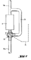
- Figure 1 is a diagrammatic illustration of a vacuum toilet system according to the invention, and
- Figure 2 is an enlarged partial view of a modification of the vacuum system shown in Figure 1.
- The vacuum toilet system shown in Figure 1 is designed for installation in a passenger transport vehicle such as a railroad car or the like.
- The illustrated system comprises a toilet with a waste-receiving bowl 1, connected to a sewer pipe 3 via a normally-closed
sewer valve 2. The sewer pipe 3 feeds, via an air separator 4, into acollecting tank 5, which is fitted with an alarm gauge 6 indicating, for example, when thecollecting tank 5 has become filled to such an extent that it requires emptying. Thecollecting tank 5 can be emptied by connecting it to the atmosphere and simultaneously applying suction to a pipe 7, which is normally closed by means of a closure valve (not shown). - The vacuum generating means is an ejector 8, evacuating the sewer pipe 3 and the
tank 5 through afilter 9 and anexhaust duct check valve 18 is provided between theexhaust duct tank 5 to prevent backflow of air into the tank and thereby preserve a level of vacuum in thetank 5 and the sewer pipe 3. The separator 4 separates the air from the discharged waste material. The separator 4 can be of a very simple design. Its object is to prevent liquid and solid matter from being sucked into theexhaust duct - The ejector 8 is operated by compressed air which is fed from a
network 17 through a remotely controlledsolenoid valve 10. Air from thecompressed air network 17 is also led, via another remotely controlled solenoid valve 11 to a pressuriser 12, which pressurises rinse water received from awater pipe 15 and delivers it to the toilet bowl 1. A third remotely controlledsolenoid valve 16 releases compressed air for operating thesewer valve 2. Aflush knob 13 on a wall 13a of the toilet compartment is connected through aninterface device 26 to a control unit 14 that controls the various functions of the system. - To execute a waste removal and flushing operation, the
flush knob 13 is operated. Theflush knob 13 sends an impulse to the control unit 14, which opens thesolenoid valve 10, permitting compressed air to pass through the ejector 8, thus generating within a few seconds a sufficient partial vacuum in thecollecting tank 5 and sewer pipe 3 for carrying out a waste removal and flushing operation. Thesolenoid valve 10 will remain open until the desired vacuum level has been reached. At a preset time in the operating cycle, the valve 11 opens and rinse water is released to thepressuriser 12, which provides the toilet bowl with rinse water under pressure. When thevalve 16 opens, compressed air acts on the operating device of thesewer valve 2 so that the sewer valve opens. The waste material in the toilet bowl 1 is then forced into the sewer pipe 3 by the difference between the ambient pressure and the partial vacuum induced in the sewer pipe 3 and is transported by this pressure difference to thecollecting tank 5. - Further toilet bowls with associated piping and other equipment may be connected to the collecting
tank 5 and to the vacuum generating means. However, a system with intermittent vacuum generation is not suitable for a system including a large number of toilet bowls. The number of toilet bowls in such a system is preferably no more than two, and the maximum number is normally four. Through special arrangements, the number of toilet bowls can be increased to about ten in a system with intermittent vacuum production, but such a system is relatively complicated. - When a train or other vehicle, equipped with the illustrated vacuum toilet system, is at rest (e.g. standing at a station), air pumped out through the
duct filter 9, which removes odoriferous material from the air. The relativelyexpensive filter 9 is, however, not used when the train is moving at a relatively high speed. In those cases, the air pumped out through theduct pass duct 20 past thefilter 9. This function is achieved by opening aclosure valve 21 present in the by-pass duct 20. Preferably, this valve has a remotely controlled operatingdevice 22, which is controlled from the control unit 14 through aconnection 24. The vehicle includes aspeed sensing device 27 that generates control signals depending on the speed of the vehicle. One of these signals is fed to the control unit 14 through aconnection 25. The speed sensing device might, for reasons not connected with the vacuum toilet system, provide a control signal when, for instance, a speed of 40 kn/h is reached, and this control signal may be used to control connection of the by-pass duct 20. Otherwise, a somewhat lower limit value, but preferably at least 20 km/h, might be more convenient. If the malodour-reducingmeans 9 has a very low flow resistance, the mere opening of thevalve 21 may not be sufficient for providing the required by-pass function. In that case, as shown in figure 2, thevalve 21 could be replaced by a remotely controlled, three-way valve 23, installed at one end of the by-pass duct 20, so that the three-way valve, dependent on its functional position, connects the by-pass duct 20 in theexhaust duct filter 9 or conversely connects thefilter 9 in theexhaust duct pass duct 20. A three-way valve connected like this, positively determines the flow path of the exhausted air and therefore gives a more reliable control of the air flow, but will be somewhat more expensive, than the arrangement shown in Figure 1. - The invention is not limited to the embodiments shown, since several variations and modifications thereof are feasible within the scope of the following claims. For example, although the invention has been described with reference to a vacuum toilet system installed in a railroad car of a train it is also applicable to other passenger transport vehicles, such as buses. Also, although vacuum is generated intermittently in connection with the use of every toilet bowl emptying into the
tank 5 shown in Figure 1, the invention is also applicable to a constant vacuum system, in which the level of partial vacuum in each pipe is monitored by a pressure sensing device and, during normal use of the system, is constantly kept between an upper and a lower limit within a range suitable for the intended sewage transport in the sewer pipe.
Claims (11)
- A method of operating a vacuum toilet system on a transport vehicle which system includes malodour-reducing means (9) to considerably reduce the objectionable effect of malodorous air periodically exhausted from the system, characterised in that the reducing means (9) is used only at vehicle speeds below a preset limit value.
- A method according to claim 1, characterised in that the transport vehicle includes means (27) for sensing the speed of the transport vehicle and generating a signal representative of the sensed speed, and in that said method comprises removing the malodour-reducing means (9) from the path of exhausted air when the speed represented by said signal exceeds said preset limit value.
- A method according to claim 1 or claim 2, characterised in that air is exhausted from the system only when a vacuum generator (8) is operated in response to a flushing impulse by a user of the toilet system to create a partial vacuum in the system necessary for waste transportation, and in that operation of the vacuum generator (8) is thereafter discontinued until the next flushing impulse occurs.
- A vacuum toilet system for a transport vehicle including at least one toilet bowl (1), a sewage collection device (3, 5), a normally-closed sewer valve (2) connected between each toilet bowl (1) and the sewage collection device (3, 5), a vacuum generator (8) for exhausting air from the sewage collection device (3, 5) to create a partial vacuum in the sewage collection device (3, 5) of a magnitude sufficient for effective transport of sewage from the toilet bowl (1) into the sewage collection device (3, 5) and a malodour-reducing means (9) for operating on the air exhausted from the sewage collection device (3, 5) by the vacuum generator (8), characterised by means (20, 21, 22) for rendering said malodour-reducing means (9) ineffective when the transport vehicle is moving at a speed that exceeds a preset limit value.
- A vacuum toilet system according to claim 4, characterised in that the malodour-reducing means includes an odour removing filter (9).
- A vacuum toilet system according to claim 4 or claim 5, characterised in that means (21) is provided for sensing the speed of the transport vehicle and automatically rendering the malodour-reducing means (9) ineffective when the speed of the transport vehicle exceeds said preset limit value.
- A method or system according to any preceding claim, characterised in that said limit value is at least 20 km/h, preferably about 40 km/h.
- A vacuum toilet system according to any of claims 4 to 7, characterised in that the means for rendering the malodour-reducing means (9) ineffective comprises a by-pass duct (20) connected in parallel with said malodour-combatting means (9).
- A vacuum toilet system according to claim 8, characterised in that the flow resistance of the by-pass duct (20) is considerably lower than the flow resistance of the malodour-reducing means (9) and in that the system includes a shut-off valve (23) connected in the by-pass duct (20).
- A vacuum toilet system according to claim 8, characterised in that an exhaust duct is provided for air drawn from the sewage collection device (3, 5), said exhaust duct having an upstream portion (19a) and a downstream portion (19b), in that the malodour-reducing means (9) is connected between the upstream portion (19a) of the exhaust duct and the downstream portion (19b) thereof, and in that the system further comprises a three-way valve (23) allowing one of said portions of the exhaust duct to be connected either to the by-pass duct (20) or the malodour-reducing means (9).
- A vacuum toilet system according to any of claims 4 to 10, characterised in that control means responsive to a toilet flushing impulse is provided to cause the vacuum generator (8) to operate until the partial vacuum necessary for transportation of waste material from the toilet bowl (1) has been generated.
Applications Claiming Priority (2)
| Application Number | Priority Date | Filing Date | Title |
|---|---|---|---|
| SE9200324 | 1992-02-05 | ||
| SE9200324A SE469832B (en) | 1992-02-05 | 1992-02-05 | Vacuum toilet system with odor filter |
Publications (2)
| Publication Number | Publication Date |
|---|---|
| EP0555984A1 EP0555984A1 (en) | 1993-08-18 |
| EP0555984B1 true EP0555984B1 (en) | 1996-10-23 |
Family
ID=20385212
Family Applications (1)
| Application Number | Title | Priority Date | Filing Date |
|---|---|---|---|
| EP93300783A Expired - Lifetime EP0555984B1 (en) | 1992-02-05 | 1993-02-03 | Malodour-prevention in mobile vacuum toilet systems |
Country Status (6)
| Country | Link |
|---|---|
| US (1) | US5369811A (en) |
| EP (1) | EP0555984B1 (en) |
| JP (1) | JP3390039B2 (en) |
| AT (1) | ATE144573T1 (en) |
| DE (1) | DE69305547T2 (en) |
| SE (1) | SE469832B (en) |
Cited By (1)
| Publication number | Priority date | Publication date | Assignee | Title |
|---|---|---|---|---|
| US8490223B2 (en) | 2011-08-16 | 2013-07-23 | Flow Control LLC | Toilet with ball valve mechanism and secondary aerobic chamber |
Families Citing this family (48)
| Publication number | Priority date | Publication date | Assignee | Title |
|---|---|---|---|---|
| DE69511695T2 (en) | 1995-09-13 | 1999-12-23 | Evac Ab Bromoella | Vacuum sewage system regulated by a membrane |
| JPH09203097A (en) * | 1996-01-29 | 1997-08-05 | Takuo Mochizuki | Excrement suction and discharge device by jet pump |
| HRP970257A2 (en) * | 1996-06-04 | 1998-02-28 | Siemens Sgp Verkehrstech Gmbh | Process and device for partially emptying in a controlled manner a waste water container in a vehicle, in particular a railway vehicle |
| FI104437B (en) * | 1998-07-01 | 2000-01-31 | Evac Int Oy | Drainage system |
| US6006373A (en) * | 1998-07-02 | 1999-12-28 | Evac International Oy | System for collecting and disposing of aircraft galley waste |
| US6158058A (en) * | 1998-09-02 | 2000-12-12 | Martens; Henry H. | Ventilated toilet |
| US6279173B1 (en) | 1999-04-12 | 2001-08-28 | D2M, Inc. | Devices and methods for toilet ventilation using a radar sensor |
| US6085366A (en) * | 1999-07-02 | 2000-07-11 | Evac International Oy | Apparatus for supplying pressurized rinse water to a toilet |
| US6317898B1 (en) * | 2000-02-25 | 2001-11-20 | Raritan Engineering Company, Inc. | Apparatus for selecting marine toilet flush water |
| FI110536B (en) * | 2001-06-21 | 2003-02-14 | Evac Int Oy | Process for transporting waste material in a vacuum sewer system |
| US6528021B1 (en) * | 2001-08-13 | 2003-03-04 | James Philip Williams | Method and apparatus for eliminating odors and killing bacteria associated with emissions from sewer and grease trap vents |
| US7207073B1 (en) | 2001-10-18 | 2007-04-24 | The American Team | Vacuum assisted toilet |
| IES20020143A2 (en) * | 2002-02-22 | 2003-01-22 | Peter Oliver Gibney | A mobile cabin with toilet facilites |
| KR20040001571A (en) * | 2002-06-28 | 2004-01-07 | 선진환경기공주식회사 | Sewage collector equipment and auto driving method thereof |
| US6817837B2 (en) | 2002-07-19 | 2004-11-16 | Walker-Dawson Interest, Inc. | Jet pump with recirculating motive fluid |
| NZ538344A (en) * | 2002-07-19 | 2006-12-22 | Walker Dawson Interests Inc | Recirculating jet pump and method of moving material |
| US6804837B1 (en) | 2003-09-09 | 2004-10-19 | Guess Sr Robert L | Odor transporter system for a toilet bowl |
| DE102005013566B4 (en) * | 2005-03-23 | 2009-12-10 | Airbus Deutschland Gmbh | Arrangement for reducing noise in vacuum systems for an aircraft |
| JP5156198B2 (en) * | 2006-04-28 | 2013-03-06 | 株式会社テシカ | Sewage treatment equipment for vehicles |
| US8516622B2 (en) * | 2006-05-08 | 2013-08-27 | Thetford Corporation | Sanitary system for a vehicle including a removable holding tank |
| FI125301B (en) * | 2006-12-21 | 2015-08-31 | Evac Oy | Vacuum drainage system and method for using a vacuum drainage system |
| JP4800999B2 (en) * | 2007-04-16 | 2011-10-26 | 日本車輌製造株式会社 | Waste disposal apparatus and railway vehicle equipped with the apparatus |
| DE102007018549A1 (en) * | 2007-04-19 | 2008-10-30 | Airbus Deutschland Gmbh | Vacuum toilet system for waste water transport and sewage collection in an airplane |
| US8151377B2 (en) * | 2007-08-12 | 2012-04-10 | Ronald Ferrell Pickle | Odorless and overflow-less toilet system |
| US20090158515A1 (en) * | 2007-12-19 | 2009-06-25 | Steve Bruno | Odor removal and air freshener system |
| JP5137656B2 (en) * | 2008-03-27 | 2013-02-06 | 北海道旅客鉄道株式会社 | Toilet excrement disposal device in moving body |
| CN201512849U (en) * | 2009-09-24 | 2010-06-23 | 山东华腾环保科技有限公司 | Vacuum assisted toilet stool |
| DE102010011881A1 (en) * | 2010-03-18 | 2011-09-22 | Siemens Aktiengesellschaft | Rail vehicle with a sanitary device |
| EP2400071A1 (en) * | 2010-06-25 | 2011-12-28 | Tecnicas Modulares E Industriales, S.A. | Vacuum toilet system |
| EP2484574B1 (en) * | 2011-02-07 | 2013-08-07 | ALSTOM Transport SA | A water storage and distribution system having a water tank by pass |
| US8683800B2 (en) | 2011-03-17 | 2014-04-01 | Ford Global Technologies, Llc | Method and system for providing vacuum |
| CN102359627B (en) * | 2011-06-30 | 2013-04-17 | 株洲南车时代电气股份有限公司 | Filter one-way valve for vacuum toilet wastewater collector |
| US9506478B2 (en) * | 2012-01-13 | 2016-11-29 | Edwards Limited | Vacuum system |
| US9352857B2 (en) | 2012-06-05 | 2016-05-31 | Hamilton Sundstrand Space Systems International, Inc. | Urine stowage system for spacecraft |
| CN102837648A (en) * | 2012-06-29 | 2012-12-26 | 上海华杰生态环境工程有限公司 | Pulling-type microbial foam toilet |
| DE102012223242A1 (en) * | 2012-12-14 | 2014-06-18 | Siemens Aktiengesellschaft | Rail vehicle with pressure shock-protected gray water pipe |
| DE102013212451B4 (en) * | 2013-06-27 | 2015-02-05 | Siemens Aktiengesellschaft | Rail vehicle with a toilet device |
| ES2491392B1 (en) * | 2014-04-15 | 2015-04-13 | Rolen Technologies & Products, S.L. | Compact vacuum toilet block |
| DE102015205825B4 (en) | 2015-03-31 | 2021-09-23 | Siemens Mobility GmbH | Method for the frost emptying of a fresh water container for a rail vehicle for passenger traffic and a rail vehicle for passenger traffic with a frost emptying device |
| CN104890592A (en) * | 2015-06-07 | 2015-09-09 | 合肥明华机电工程有限公司 | Vacuum washroom for coach |
| CN105644463B (en) * | 2015-12-29 | 2021-10-29 | 宜为客有限公司 | Vacuum toilet system for vehicle |
| US20170306604A1 (en) * | 2016-04-22 | 2017-10-26 | Yahe Zhang | Eliminate odor toilet with a jet device |
| CN106120999B (en) * | 2016-06-30 | 2019-04-26 | 中铁伟业(宁波)轨道交通装备有限公司 | Peculiar smell guidance system in train closet |
| CN106379357A (en) * | 2016-09-29 | 2017-02-08 | 青岛轶骋铁路真空系统制造有限公司 | Vacuum maintaining type feces-collection system with separator |
| EP3743566A4 (en) * | 2019-03-21 | 2021-09-15 | Brigham Young University | Vacuum-assisted toilet systems and methods of using the same |
| US10994845B2 (en) * | 2019-06-06 | 2021-05-04 | B/E Aerospace, Inc. | Waste system pressure management system |
| CN110539765A (en) * | 2019-08-13 | 2019-12-06 | 株洲车城机车配件股份有限公司 | Novel compact transfer type vacuum excrement collector |
| FR3113650A1 (en) * | 2020-09-01 | 2022-03-04 | Airbus (S.A.S.) | Aircraft incorporating a lavatory intended to contain the effects of a malicious device. |
Family Cites Families (12)
| Publication number | Priority date | Publication date | Assignee | Title |
|---|---|---|---|---|
| US1417268A (en) * | 1922-05-23 | of horton | ||
| US1276784A (en) * | 1913-11-24 | 1918-08-27 | Gould Coupler Co | Closet. |
| US1613848A (en) * | 1925-04-28 | 1927-01-11 | John H Allen | Passenger-car waste-transfer apparatus |
| US1749356A (en) * | 1928-08-09 | 1930-03-04 | Oscar A Ross | Sewage control for moving vehicles |
| US1818586A (en) * | 1930-01-10 | 1931-08-11 | Charles B Schumacher | Dry closet |
| US2047067A (en) * | 1935-06-04 | 1936-07-07 | Harris Thompson | Air conditioner for bathrooms |
| US2612186A (en) * | 1947-05-20 | 1952-09-30 | William B Bolger | Fluid pressure operated flow control valve |
| US4184506A (en) * | 1973-12-29 | 1980-01-22 | Krister Nordberg | Vacuum sewer system |
| US4029487A (en) * | 1975-05-12 | 1977-06-14 | Spectroderm, Inc. | Apparatus for protecting vacuum sources including valve which alternately communicates with vacuum and atmosphere |
| FI66670C (en) * | 1978-08-25 | 1985-02-01 | Waertsilae Oy Ab | AVLOPPSSYSTEM |
| FI83797C (en) * | 1988-10-05 | 1991-08-26 | Nesite Oy | AVLOPPSSYSTEM. |
| SE501960C2 (en) * | 1990-04-20 | 1995-06-26 | Waertsilae Oy Ab | Vacuum toilet system with vacuum generator with substantially constant operating time |
-
1992
- 1992-02-05 SE SE9200324A patent/SE469832B/en not_active IP Right Cessation
-
1993
- 1993-01-13 US US08/003,536 patent/US5369811A/en not_active Expired - Lifetime
- 1993-02-03 DE DE69305547T patent/DE69305547T2/en not_active Expired - Fee Related
- 1993-02-03 AT AT93300783T patent/ATE144573T1/en not_active IP Right Cessation
- 1993-02-03 EP EP93300783A patent/EP0555984B1/en not_active Expired - Lifetime
- 1993-02-04 JP JP01713593A patent/JP3390039B2/en not_active Expired - Fee Related
Cited By (1)
| Publication number | Priority date | Publication date | Assignee | Title |
|---|---|---|---|---|
| US8490223B2 (en) | 2011-08-16 | 2013-07-23 | Flow Control LLC | Toilet with ball valve mechanism and secondary aerobic chamber |
Also Published As
| Publication number | Publication date |
|---|---|
| SE9200324D0 (en) | 1992-02-05 |
| JP3390039B2 (en) | 2003-03-24 |
| DE69305547D1 (en) | 1996-11-28 |
| DE69305547T2 (en) | 1997-02-20 |
| ATE144573T1 (en) | 1996-11-15 |
| SE469832B (en) | 1993-09-27 |
| JPH05270404A (en) | 1993-10-19 |
| SE9200324L (en) | 1993-08-06 |
| US5369811A (en) | 1994-12-06 |
| EP0555984A1 (en) | 1993-08-18 |
Similar Documents
| Publication | Publication Date | Title |
|---|---|---|
| EP0555984B1 (en) | Malodour-prevention in mobile vacuum toilet systems | |
| US5396668A (en) | System for discharging wastes | |
| US5214807A (en) | Vacuum toilet system | |
| US4865631A (en) | Vacuum sewage system | |
| EP0530859B1 (en) | Vacuum toilet system | |
| JPS6234578B2 (en) | ||
| US8011033B2 (en) | Aircraft sink with integrated waste disposal function | |
| US6223361B1 (en) | Galley waste disposal system | |
| RU2250168C2 (en) | Vacuum toilet system | |
| EP0931720B2 (en) | Galley vacuum waste disposal system | |
| US4816167A (en) | Portable system for dewatering contents of sanitary sewer traps | |
| JPH07207745A (en) | Vacuum type sewerage device | |
| US5299327A (en) | Sewer ventilator system for recreational vehicles, boats and the like | |
| EP0436357B1 (en) | Vacuum sewer arrangement | |
| GB2070694A (en) | Sewage collection and disposal apparatus | |
| EP0515134B1 (en) | Improvements in and relating to vacuum sewage systems | |
| JP3532486B2 (en) | Deodorizing device for vacuum toilets for transport vehicles | |
| US3571822A (en) | Toilet facility ventilation system | |
| EP1291468A2 (en) | Vacuum flush system with temporary-retention waste water tank | |
| JP2002502472A (en) | Toilet device with vacuum extraction | |
| CN209149119U (en) | For aircraft kitchen buck/discharge of wastewater new device | |
| JP3344998B1 (en) | Human waste collection truck | |
| JPH05193703A (en) | Garbage collector | |
| JPH09301504A (en) | Deodorizing device for garbage pneumatic transportion device | |
| JPH06206604A (en) | Method for discharging dust container by air extraction |
Legal Events
| Date | Code | Title | Description |
|---|---|---|---|
| PUAI | Public reference made under article 153(3) epc to a published international application that has entered the european phase |
Free format text: ORIGINAL CODE: 0009012 |
|
| AK | Designated contracting states |
Kind code of ref document: A1 Designated state(s): AT CH DE FR GB LI |
|
| 17P | Request for examination filed |
Effective date: 19940121 |
|
| 17Q | First examination report despatched |
Effective date: 19951206 |
|
| GRAH | Despatch of communication of intention to grant a patent |
Free format text: ORIGINAL CODE: EPIDOS IGRA |
|
| GRAH | Despatch of communication of intention to grant a patent |
Free format text: ORIGINAL CODE: EPIDOS IGRA |
|
| GRAA | (expected) grant |
Free format text: ORIGINAL CODE: 0009210 |
|
| AK | Designated contracting states |
Kind code of ref document: B1 Designated state(s): AT CH DE FR GB LI |
|
| REF | Corresponds to: |
Ref document number: 144573 Country of ref document: AT Date of ref document: 19961115 Kind code of ref document: T |
|
| REF | Corresponds to: |
Ref document number: 69305547 Country of ref document: DE Date of ref document: 19961128 |
|
| REG | Reference to a national code |
Ref country code: CH Ref legal event code: NV Representative=s name: A. BRAUN, BRAUN, HERITIER, ESCHMANN AG PATENTANWAE |
|
| ET | Fr: translation filed | ||
| PLBE | No opposition filed within time limit |
Free format text: ORIGINAL CODE: 0009261 |
|
| STAA | Information on the status of an ep patent application or granted ep patent |
Free format text: STATUS: NO OPPOSITION FILED WITHIN TIME LIMIT |
|
| 26N | No opposition filed | ||
| REG | Reference to a national code |
Ref country code: GB Ref legal event code: IF02 |
|
| PGFP | Annual fee paid to national office [announced via postgrant information from national office to epo] |
Ref country code: AT Payment date: 20030109 Year of fee payment: 11 |
|
| PGFP | Annual fee paid to national office [announced via postgrant information from national office to epo] |
Ref country code: FR Payment date: 20030113 Year of fee payment: 11 |
|
| PGFP | Annual fee paid to national office [announced via postgrant information from national office to epo] |
Ref country code: GB Payment date: 20030116 Year of fee payment: 11 |
|
| PGFP | Annual fee paid to national office [announced via postgrant information from national office to epo] |
Ref country code: DE Payment date: 20030120 Year of fee payment: 11 |
|
| PGFP | Annual fee paid to national office [announced via postgrant information from national office to epo] |
Ref country code: CH Payment date: 20030121 Year of fee payment: 11 |
|
| PG25 | Lapsed in a contracting state [announced via postgrant information from national office to epo] |
Ref country code: GB Free format text: LAPSE BECAUSE OF NON-PAYMENT OF DUE FEES Effective date: 20040203 Ref country code: AT Free format text: LAPSE BECAUSE OF NON-PAYMENT OF DUE FEES Effective date: 20040203 |
|
| PG25 | Lapsed in a contracting state [announced via postgrant information from national office to epo] |
Ref country code: LI Free format text: LAPSE BECAUSE OF NON-PAYMENT OF DUE FEES Effective date: 20040229 Ref country code: CH Free format text: LAPSE BECAUSE OF NON-PAYMENT OF DUE FEES Effective date: 20040229 |
|
| PG25 | Lapsed in a contracting state [announced via postgrant information from national office to epo] |
Ref country code: DE Free format text: LAPSE BECAUSE OF NON-PAYMENT OF DUE FEES Effective date: 20040901 |
|
| GBPC | Gb: european patent ceased through non-payment of renewal fee |
Effective date: 20040203 |
|
| REG | Reference to a national code |
Ref country code: CH Ref legal event code: PL |
|
| PG25 | Lapsed in a contracting state [announced via postgrant information from national office to epo] |
Ref country code: FR Free format text: LAPSE BECAUSE OF NON-PAYMENT OF DUE FEES Effective date: 20041029 |
|
| REG | Reference to a national code |
Ref country code: FR Ref legal event code: ST |