EP0555872B1 - Optical apparatus for emitting light - Google Patents
Optical apparatus for emitting light Download PDFInfo
- Publication number
- EP0555872B1 EP0555872B1 EP93102258A EP93102258A EP0555872B1 EP 0555872 B1 EP0555872 B1 EP 0555872B1 EP 93102258 A EP93102258 A EP 93102258A EP 93102258 A EP93102258 A EP 93102258A EP 0555872 B1 EP0555872 B1 EP 0555872B1
- Authority
- EP
- European Patent Office
- Prior art keywords
- lens
- barrel
- laser beam
- light source
- irradiating
- Prior art date
- Legal status (The legal status is an assumption and is not a legal conclusion. Google has not performed a legal analysis and makes no representation as to the accuracy of the status listed.)
- Expired - Lifetime
Links
- 230000003287 optical effect Effects 0.000 title claims description 93
- 239000004065 semiconductor Substances 0.000 claims description 25
- 239000000853 adhesive Substances 0.000 claims description 19
- 230000001070 adhesive effect Effects 0.000 claims description 19
- 239000012780 transparent material Substances 0.000 claims description 3
- 230000001678 irradiating effect Effects 0.000 description 52
- 238000001514 detection method Methods 0.000 description 17
- 239000000835 fiber Substances 0.000 description 5
- 230000005855 radiation Effects 0.000 description 5
- 238000005259 measurement Methods 0.000 description 4
- 230000005484 gravity Effects 0.000 description 3
- 239000010453 quartz Substances 0.000 description 3
- VYPSYNLAJGMNEJ-UHFFFAOYSA-N silicon dioxide Inorganic materials O=[Si]=O VYPSYNLAJGMNEJ-UHFFFAOYSA-N 0.000 description 3
- 230000005540 biological transmission Effects 0.000 description 2
- 238000010586 diagram Methods 0.000 description 2
- 238000003384 imaging method Methods 0.000 description 2
- 238000002347 injection Methods 0.000 description 2
- 239000007924 injection Substances 0.000 description 2
- 239000002184 metal Substances 0.000 description 2
- 101100242909 Streptococcus pneumoniae (strain ATCC BAA-255 / R6) pbpA gene Proteins 0.000 description 1
- 230000003247 decreasing effect Effects 0.000 description 1
- 230000002950 deficient Effects 0.000 description 1
- 230000000694 effects Effects 0.000 description 1
- 230000017525 heat dissipation Effects 0.000 description 1
- 239000000463 material Substances 0.000 description 1
- 238000000034 method Methods 0.000 description 1
- 229920002492 poly(sulfone) Polymers 0.000 description 1
- 239000011347 resin Substances 0.000 description 1
- 229920005989 resin Polymers 0.000 description 1
- 238000005476 soldering Methods 0.000 description 1
Images






Classifications
-
- G—PHYSICS
- G11—INFORMATION STORAGE
- G11B—INFORMATION STORAGE BASED ON RELATIVE MOVEMENT BETWEEN RECORD CARRIER AND TRANSDUCER
- G11B7/00—Recording or reproducing by optical means, e.g. recording using a thermal beam of optical radiation by modifying optical properties or the physical structure, reproducing using an optical beam at lower power by sensing optical properties; Record carriers therefor
- G11B7/12—Heads, e.g. forming of the optical beam spot or modulation of the optical beam
- G11B7/22—Apparatus or processes for the manufacture of optical heads, e.g. assembly
-
- G—PHYSICS
- G11—INFORMATION STORAGE
- G11B—INFORMATION STORAGE BASED ON RELATIVE MOVEMENT BETWEEN RECORD CARRIER AND TRANSDUCER
- G11B7/00—Recording or reproducing by optical means, e.g. recording using a thermal beam of optical radiation by modifying optical properties or the physical structure, reproducing using an optical beam at lower power by sensing optical properties; Record carriers therefor
- G11B7/12—Heads, e.g. forming of the optical beam spot or modulation of the optical beam
- G11B7/125—Optical beam sources therefor, e.g. laser control circuitry specially adapted for optical storage devices; Modulators, e.g. means for controlling the size or intensity of optical spots or optical traces
Definitions
- the present invention relates to an optical apparatus for emitting light such as a laser beam collimator unit used in an image recording apparatus for recording an image by scanning a laser beam modulated according to an image signal on a recording medium, or a pickup unit of an optical disk using a semi-conductor laser light source.
- a semi-conductor laser light source 1X, a collimator lens 2X, an imaging optical system 3X, a polygonal mirror 4X as a deflector, an f ⁇ lens 5X comprising a spherical lens, a toric lens and the like, and a photosensitive drum 6X as a recording medium are arranged in the order named along an optical path.
- a laser beam modulated according to an image signal and emitted from the semi-conductor laser light source 1X is collimated by the collimator lens 2X, and the collimated beam is transmitted through the imaging optical system 3X.
- the beam is then deflected and scanned by the polygonal mirror 4X, and forms an image on the photosensitive drum 6X by the f ⁇ lens 5X.
- Fig. 16 is a longitudinal sectional view of a conventional optical apparatus for emitting light (laser unit) of this type.
- the semi-conductor laser light source 1X is urged against a base 7X by an electrical circuit board 9X and a spring 11X.
- the electrical circuit board 9X is fixed to the base 7X by a screw 13X.
- a hollow holder 8X formed in a substantially convex shape mounts therein a lens-barrel 10X which incorporates a collimator lens 2X.
- the lens-barrel 10X Upon adjustment of the focusing position and the irradiating position, the lens-barrel 10X is moved in an optical axis direction (a direction of an arrow A in Fig. 16), and is then held at a position where the diameter of a laser beam transmitted through the collimator lens 2X has a minimum value. Thereafter, an adhesive (not shown) is filled from a hole 14X into the holder 8X to fix the lens-barrel 10X to the holder 8X, thus adjusting the focusing position.
- an adhesive (not shown) is filled from a hole 14X into the holder 8X to fix the lens-barrel 10X to the holder 8X, thus adjusting the focusing position.
- the base 7X of the semi-conductor laser light source 1X is two-dimensionally moved on a plane perpendicular to the optical axis of the light source 1X, so that the central axis of the lens-barrel 10X coincides with the optical axis of the light source 1X.
- the base 7X is fixed to the holder 8X by a screw 12X, thus adjusting the irradiating position.
- the optical apparatus for emitting light is discarded as a defective product.
- the adhesive is removed, and the lens-barrel 10X is moved in the optical axis direction again to correct the shift of the focusing position.
- an adhesive (not shown) is filled from the hole 14X into the holder 8X to fix the lens-barrel 10X to the holder 8X.
- the above conventional problems 1) and 3) at least partially are overcome by the optical apparatus for emitting light of the kind defined by the JP-A-1 238 612 according to which two diametrically opposed injection ports pass the lens-barrel to receive the adhesive which thereby fixes the collimator lens and the lens-barrel to the fixation holder.
- These injection ports lie on an axis which is perpendicular to the optical axis direction.
- the EP-A-O 094 274 discloses an adjustment apparatus for adjusting focusing and irradiating positions of an optical apparatus.
- the DE-A-34 13 748 discloses an optical system consisting of a semi-conductor laser and optical means for collimating the light irradiated from said laser.
- the laser and the optical means are housed in separate fixation holders which can be adjusting with respect to one another in such a kind that a criterion concerning the laser light is optimally fulfilled. Both fixation holders will be connected with one another following to successful adjustment.
- the present invention has been made in consideration of the conventional problems, and has an object to provide an optical apparatus for emitting light of the kind defined by the precharacterizing features of claim 1 to minimize positional shift of the collimator lens upon radiation of adhesive curing radiation and to uniformly fill the adhesive.
- a laser beam emitted from the semi-conductor laser light source is substantially collimated by the collimator lens incorporated in the lens-barrel.
- the lens-barrel is moved in the optical axis direction by holding the collars of the lens-barrel which holds the collimator lens, and the lens-barrel is held at a position where the diameter of the laser beam has a minimum value, thus adjusting the focusing position.
- the lens-barrel is then two-dimensionally moved on a plane perpendicular to the optical axis direction, thereby adjusting the irradiating position. Then, an ultraviolet ray is radiated onto the lens-barrel from the ultraviolet ray radiating device to cure an ultraviolet curing adhesive, thereby fixing the lens-barrel to the fixation holder.
- the focusing and irradiating positions can be adjusted by moving the lens-barrel alone as an adjustment member.
- the lens-barrel is formed of a transparent material, which allows easy transmission of an ultraviolet ray, so as to quickly cure the ultraviolet curing adhesive.
- slits extending in the optical axis direction are formed in a fitting portion of the lens-barrel onto the fixation holder so as to shorten the curing time, to minimize a positional shift of the collimator lens caused by thermal deformation of the lens-barrel upon radiation of the ultraviolet ray, and to uniformly fill the adhesive.
- a gap is formed between the outer surface of the fixation holder and the inner surface of the lens-barrel, and the lens-barrel has the collars as members for holding the lens-barrel upon adjustment of these positions.
- the control means controls to drive the three-dimensional positioning mechanism until the second position detection means detects that the outer diameter and irradiating position of the laser beam respectively reach a minimum value and a proper irradiating position.
- the lens-barrel is moved by the three-dimensional positioning mechanism in the optical axis direction, and in two-dimensional directions on the plane perpendicular to the optical axis, and is held at a three-dimensionally proper position, thus ending adjustment of the focusing and irradiating positions.
- the control means controls to drive the three-dimensional positioning mechanism until the irradiating position of the laser beam falls within the specified value range.
- the lens-barrel is moved by the three-dimensional positioning mechanism in the two-dimensional directions on the plane perpendicular to the optical axis direction, and the irradiating position of the laser beam falls within the specified value range.
- the control means controls to drive the three-dimensional positioning mechanism until the outer diameter and irradiating position of the laser beam respectively reach a minimum value and a proper irradiating position.
- the lens-barrel is moved by the three-dimensional positioning mechanism in the optical axis direction, and in two-dimensional directions on the plane perpendicular to the optical axis, and is held at a three-dimensionally proper position, thus ending adjustment of the focusing and irradiating positions.
- Fig. 1 is a side view of an optical apparatus for emitting light according to an embodiment of the present invention
- Fig. 2 is a top view showing a partial section of Fig. 1
- Fig. 3 is a perspective view of a lens-barrel shown in Figs. 1 and 2.
- an optical apparatus 23 for emitting light includes a metal fixation holder 8 integrally comprising a fixation plate 8a on its lower portion, a lens-barrel 10 mounted on a cylindrical portion of the fixation holder 8 and formed of a transparent material, and an electrical circuit board 9 attached to a side plate of the fixation holder 8.
- a positioning hole 22, a positioning elongated hole 21, and a fixation screw hole 20 are formed in the fixation plate 8a of the fixation holder 8.
- a semi-conductor laser light source 1 is fitted under pressure in one end portion of the cylindrical portion of the fixation holder 8, and three terminals 1a, 1b, and 1c of the semi-conductor laser light source 1 are connected to the electrical circuit board 9 by soldering.
- a current is supplied to the laser light source 1 through the terminals 1a, 1b, and 1c, a laser beam 12 is emitted from the semi-conductor laser light source 1 in a direction of an arrow Z (Figs. 1 and 2).
- the lens-barrel 10 stores and holds a collimator lens 2 and an aperture 16 in one end portion.
- the other end portion of the lens-barrel 10 is fitted on the other end portion of the cylindrical portion of the fixation holder 8.
- the lens-barrel 10 is formed of a transparent resin material such as polysulfone, so as to allow easy transmission of an ultraviolet ray (to be described later).
- Two collars 17a and 17b as holding portions are integrally formed so as to project from the outer circumferential surface of the lens-barrel 10.
- slits 15a, 15b, and 15c (the remaining three slits are not shown) extending in an optical axis direction (the direction of the arrow Z) are formed at equal angular intervals on the fitting portion of the lens-barrel 10 onto the fixation holder 8, i.e., a portion opposite to the collimator lens 2 with respect to the two collars 17a and 17b.
- An annular gap 19 is defined between the inner circumferential surface of the fitting portion of the lens-barrel 10 and the outer circumferential surface of the cylindrical portion of the fixation holder 8, and an ultraviolet curing adhesive 18 is uniformly filled in the gap 19.
- the lens-barrel 10 is movable with respect to the fixation holder 8 in the optical axis direction Z and in two-dimensional directions (directions of arrows X and Y in Figs. 1 and 2) on a plane perpendicular to the optical axis direction.
- a laser beam emitted from the semi-conductor laser light source 1 is collimated by the collimator lens 2, and the collimated beam is beam-shaped into a cylindrical shape by the aperture 16.
- the lens-barrel 10 Upon adjustment of the focusing and irradiating positions, the lens-barrel 10 is moved in the optical axis direction Z, and is held at a position where the diameter of the laser beam 12 has a minimum value, thereby adjusting the focusing position.
- the lens-barrel 10 is moved in the two-dimensional directions (the directions of the arrows X and Y) on the plane perpendicular to the optical axis direction Z, so that the optical axis of the semi-conductor laser light source 1 coincides with that of the lens-barrel 10, thereby adjusting the irradiating position.
- an ultraviolet ray is radiated from an ultraviolet ray radiating device (not shown; to be described later) onto the fitting portion of the lens-barrel 10 to cure the ultraviolet curing adhesive 18, thereby fixing the lens-barrel 10 to the fixation holder 8.
- the fixation holder 8 comprises a metal member.
- Fig. 4 is a schematic front view of the optical apparatus for emitting light shown in Figs. 1 and 2, and the automatic adjustment apparatus for adjusting the focusing and irradiating positions of the optical apparatus for emitting light
- Fig. 5 is an enlarged front view showing the optical apparatus for emitting light and a three-dimensional positioning mechanism shown in Fig. 4
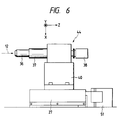
- Fig. 6 is an enlarged front view of an enlarging optical system shown in Fig. 4
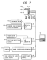
- Fig. 7 is a control block diagram of the automatic adjustment apparatus for adjusting the focusing and irradiating positions of the optical apparatus for emitting light shown in Fig. 4, Fig.
- Fig. 8 is a flow chart for explaining the former half of an operation of the automatic adjustment apparatus for adjusting the focusing and irradiating positions of the optical apparatus for emitting light shown in Fig. 4, and Fig. 9 is a flow chart for explaining the latter half of the operation.
- the automatic adjustment apparatus for adjusting the focusing and irradiating positions of the optical apparatus for emitting light includes the optical apparatus 23 for emitting light (Figs. 1 and 2) fixed to a positioning fixation jig 41 of a support base 39, a three-dimensional positioning mechanism 4 having a clamp means for clamping the lens-barrel 10 of the optical apparatus 23 for emitting light, for three-dimensionally moving and positioning the lens-barrel 10, a first position detection means 14, and an enlarging optical system 44 as a second position detection means.
- the positioning fixation jig 41 is fixed on the upper surface of the support base 39 for supporting the optical apparatus 23 for emitting light.
- the fixation holder 8 (see Figs. 1 and 2) is positioned in the positioning fixation jig 41 by inserting pins (not shown) of the positioning fixation jig 41 into the positioning hole 22 and the positioning elongated hole 21 of the fixation holder 8 of the optical apparatus 23 for emitting light, respectively.
- the fixation holder 8 is fixed to the positioning fixation jig 41 by a fixation screw (not shown) extending through the fixation screw hole 20 (see Fig. 1).
- One end of a substantially L-shaped pressing member 31a is coupled to the output shaft of a pushing air cylinder 31 mounted on the support base 39.
- the cylindrical portion of the fixation holder 8 is pressed toward the positioning fixation jig 41 by the other end of the member 31a.
- the ultraviolet curing adhesive 18 (see Fig. 1) in the lens-barrel 10 is not cured yet.
- An ultraviolet ray radiation device 3 comprising three quartz fibers 30a and 30b (one quartz fiber is not shown), and an ultraviolet ray generation source is mounted on the support base 39.
- a power meter 53 measures the light amount of the laser beam 12, and the measurement value is fetched by a personal computer (not shown), as will be described later.
- the known three-dimensional positioning mechanism 4 includes a Z-axis adjustment stage 24 which is moved and positioned in the Z-axis direction by a Z-axis pulse motor 5, a Y-axis adjustment stage 25 which is mounted on the Z-axis adjustment stage 24, and is moved and positioned in the Y-axis direction by a Y-axis pulse motor 6, an X-axis adjustment stage 26, which is mounted on the Y-axis adjustment stage 25, and is moved and positioned in the X-axis direction by an X-axis pulse motor 7.
- the X-axis adjustment stage 26 of the three-dimensional positioning mechanism 4 mounts two clamp air cylinders 28a and 28b as clamp means to be described later. Clamp nails 29a (one clamp nail is not shown) for clamping and holding the two collars 17a and 17b (see Fig. 1) of the lens-barrel 10 are respectively coupled to the output shafts of the clamp air cylinders 28a and 28b.
- the first position detection means 14 includes a support base 11 arranged aside the three-dimensional positioning mechanism 4, a slider 42 mounted on the support base 11, and moved in the Y-axis direction by an air cylinder (not shown), a beam splitter 35 and a position detection sensor 34 mounted on the slider 42.
- the position detection sensor 34 comprises a PSD (trade name; available from Hamamatsu Photonics (K.K.)).
- PSD trade name; available from Hamamatsu Photonics (K.K.)
- the optical axis position of reflected light (not shown) of the laser beam 12 is detected by the position detection sensor 34, thereby detecting the optical axis positions, in the directions of the arrows X and Y, of the incident laser beam 12, i.e., the irradiating position of the laser beam 12.
- a reflection mirror may be used in place of the beam splitter 35.
- the enlarging optical system 44 as the second position detection means includes an optical system moving stage 27 moved and positioned in the direction of the arrow Z by a pulse motor 51, a lens-barrel 37 for holding an enlarging objective lens 36 and a camera 38, which are mounted on the optical system moving stage 27 via a support base 40.
- the laser beam 12 is incident on the objective lens 36, and is enlarged.
- the image of the laser beam 12 is photographed in an enlarged scale by the camera 38, and the photographed image of the laser beam 12 is fetched by an image processing apparatus 48 (see Fig. 7).
- the image processing apparatus 48 executes image processing of the photographed image of the laser beam 12 to detect the outer diameter of the laser beam, and its central position (irradiating position) in the two-dimensional directions of the arrows X and Y. These detection values are transferred to a computer (not shown; to be described later), and it is detected whether or not the detected outer diameter has a minimum value, and the detected central position is an optimal position, i.e., the central position of an image.
- Control means for the above-mentioned automatic adjustment apparatus for adjusting the focusing and irradiating positions of the optical apparatus for emitting light will be described below with reference to Figs. 4 to 6 and Fig. 7.
- a laser power source 49 controlled by a personal computer 50 supplies a current to the terminals 1a, 1b, and 1c (see Fig. 1) of the semi-conductor laser light source 1.
- the irradiating position in the two-dimensional directions of the laser beam 12 detected by the position detection sensor 34 is converted by an A/D converter 47 into a digital value, and the digital value is input to the personal computer 50.
- Z-, Y-, and X-axis pulse motor controllers 45a, 45b, and 45c respectively control to drive the Z-, Y-, and X-axis pulse motors 5, 6, and 7 of the three-dimensional positioning mechanism 4, and a pulse motor controller 51a controls to drive the pulse motor 51 of the enlarging optical system 44.
- the personal computer 50 automatically controls the controllers 45a, 45b, 45c, and 51a for three-dimensionally moving the irradiating position of the laser beam 12 and the lens-barrel 10, and also automatically controls the above-mentioned image processing apparatus 48. Furthermore, the personal computer 50 controls to drive the controllers 45a, 45b, and 45c on the basis of the outer diameter and the central position of the laser beam 12 measured by the image processing apparatus 48 via the camera 38, so that the outer diameter and the central position of the laser beam 12 are respectively a minimum value and an optimal position, thereby automatically adjusting the focusing and irradiating positions, as will be described later.
- a digital I/O 46 inputs/outputs an open/close signal of a solenoid valve 52a for each air cylinder, and a detection value of a forward and backward detection sensor 52b for each air cylinder.
- the optical apparatus 23 for emitting light is positioned on the positioning fixation jig 41 by inserting the two pins (not shown) in the positioning elongated hole 21 and the positioning hole hole 22 of the fixation plate 8a of the fixation holder 8, and is then fixed thereto by a screw (not shown) (step 60).
- the pushing air cylinder 31 is driven, so that the optical apparatus 23 for emitting light is pushed by the pressing member 31a and is fixed to the positioning fixation jig 41 (step 61). In this state, the ultraviolet curing adhesive 18 filled in advance in the lens-barrel 10 is not cured yet.
- the slider 42, and therefore, the beam splitter 35, of the first position detection means 14 is located at a standby position, and the Z-, Y-, and X-axis adjustment stages 24, 25, and 26, and the optical system moving stage 27 also stand by at predetermined standby positions.
- the two clamp air cylinders 28a and 28b are driven to close the two clamp nails, thereby clamping and holding the two collars 17a and 17b of the lens-barrel 10 (step 62).
- a power meter 53 is moved forward by an air cylinder (not shown), so that it is located on the output optical axis of the semi-conductor laser light source 1 (step 63).
- a contact pin moving air cylinder 32 is driven to bring contact pins 43 into contact with predetermined portions of the electrical circuit board 9 of the optical apparatus 23 for emitting light (step 64), and a current is gradually supplied from the laser power source 49 to the semi-conductor laser light source 1 according to a command from the personal computer 50, thus causing the semi-conductor laser light source 1 to emit light (step 65).
- the light amount of the laser beam 12 emitted from the semi-conductor laser light source 1 is measured by the power meter 53 (step 66), and the measurement value is fetched by the personal computer 50 via the A/D converter 47.
- the power meter 53 is moved backward (step 68).
- the output laser beam 12 is substantially collimated by the collimator lens 2 incorporated in the lens-barrel 10, and is beam-shaped into a cylindrical shape by the aperture 16.
- the beam is then focused by a jig lens 33, and is incident on the objective lens 36 of the enlarging optical system 44.
- the position of the lens-barrel 10 in the directions of the arrows X and Y may often be shifted as largely as not to allow the laser beam 12 to become incident on the objective lens 36 of the enlarging optical system 44.
- the slider 42 of the first position detection means 14 is driven by an air cylinder (not shown), and the beam splitter 35 on the slider 42 is moved forward until it reaches a position on the optical axis of the laser beam 12 (step 69).
- the irradiating position, in the directions of the arrows X and Y, of reflected light (not shown) of the laser beam 12 reflected by the beam splitter 35 is detected by the position detection sensor 34 (step 70).
- the position detection sensor 34 outputs as analog values the positions of centers of gravity, in the directions of the arrows X and Y, of the light amount of the laser beam 12 to the A/D converter 47, and these values are fetched by the personal computer 50 via the A/D converter 47.
- the personal computer 50 controls to drive the Y- and X-axis pulse motor controllers 45b and 45c based on the calculation value, thereby moving the Y- and X-axis adjustment stages 25 and 26 in the directions of the arrows X and Y until the measurement value of the irradiating position falls within the specified range.
- the irradiating position is coarsely adjusted, so that the laser beam 12 is incident on the enlarging optical system 44.
- the slider 42 is moved backward by the air cylinder (not shown), and the beam splitter on the slider 42 is moved backward to its standby position (step 72).
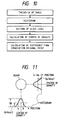
- the Z-axis pulse motor controller 45a is controlled to be driven according to a command from the personal computer 50, and the Z-axis adjustment stage 24, and hence, the lens-barrel 10 is moved in the direction of the arrow Z within a range of about ⁇ 0.6 mm of the best focusing position estimated from the laser unit outer dimensions. Then, the moving amount of the lens-barrel 10, the irradiating position, and the beam diameter are fetched. The irradiating position is measured as follows. As shown in Figs. 10 and 11, the personal computer 50 executes image processing of the fetched laser beam data, and forms histograms in the directions of the arrows X and Y by plotting sensor outputs.
- the quotient obtained by dividing a peak value Vp of each histogram by exp2 is defined as a slice level, and the positions of centers of gravity in the directions of the arrows X and Y are calculated for data exceeding the slice level by the personal computer 50 according to the following formula (1).
- the moving amount of the lens-barrel 10 is measured by counting moving command pulses of the Z-axis adjustment stage 24 by the personal computer 50.
- the movement position of the lens-barrel 10 obtained when the outer diameter of the image of the laser beam 12 has a minimum value corresponds to the just focusing position.
- the movement position of the lens-barrel 10 at that time is calculated by the personal computer 50, and the irradiating position of the beam at that time is also calculated (step 74).
- the personal computer 50 controls to drive the Z-, Y-, and X-axis pulse motor controllers 45a, 45b, and 45c on the basis of the calculation results, and the Z-, Y-, and X-axis adjustment stages 24, 25, and 26 are sequentially moved and adjusted, so that the lens-barrel is three-dimensionally located at the proper focusing position and the optimal irradiating position (steps 75 and 76).
- An ultraviolet ray is radiated from the ultraviolet ray radiating device 3 onto the lens-barrel 10 via the quartz fibers 30a and 30b (there are three fibers although one fiber is not shown) so as to cure the ultraviolet curing adhesive 18 (see Fig. 1), thereby fixing the lens-barrel 10 to the holder 8 (step 77). Thereafter, the two clamp nails 29a are released (step 78), and the pulse motor controller 51a is controlled to be driven according to a command from the personal computer 50. Thus, the enlarging optical system 44 is moved in the direction of the arrow X by the optical system moving stage 27.
- the movement position of the enlarging optical system 44 is fetched by the personal computer 50, and the irradiating position of the image and the beam diameter of the laser beam 12 measured by the image processing apparatus 48 are also transferred to the personal computer 50 as in the above-mentioned adjustment.
- the personal computer 50 confirms if the focusing and irradiating positions fall within specified ranges (step 79). Thus, the adjustment is finished.
- the pushing air cylinder is moved backward, and the screw is removed (step 80) so as to remove the optical apparatus 23 for emitting light as the laser unit from the positioning fixation jig 41 (step 81). Then, the next sample is attached to the jig 41 (step 60), and the operations in steps 61 to 81 are repeated.
- the focusing position is measured on the basis of the laser beam diameter.
- the present invention is not limited to this.
- the focusing position may be measured based on the peak value of the light amount of the laser beam. A method of measuring the light amount of the laser beam will be described below with reference to Fig. 14.
- the lens-barrel 10 is gradually moved in the direction of the arrow Z by the Z-axis adjustment stage 24, and the position of the lens-barrel 10 is measured by counting moving pulses by the personal computer 50.
- the peak value of the light amount of the laser beam 12 incident on the camera 38 is fetched by the personal computer 50 via the image processing apparatus 48.
- the movement position is represented by t
- the peak value of the light amount is represented by p
- data (t 1 , p 1 ), (t 2 , p 2 ),..., (t i , p i ),..., (t n , p n ) are obtained.
- a moving average is calculated to remove a noise component of the light amount. That is, the movement position and the peak value of the light amount are represented by (t i , ((p i-1 ) + (p i ) + (p i+1 ))/3). The maximum value of all the peak values of the light amount is calculated, and a value 90% the maximum value is defined as a slice level. If the movement positions of the lens-barrel 10 at crossing points between the slice level and a histogram of the light amount are represented by t a and t b , the just focusing position is expressed by (t a + t b )/2.
- the adjustment time can be shortened, and the adjustment yield can be improved.
- a low-cost, compact apparatus can be realized since the number of components is decreased.
Landscapes
- Physics & Mathematics (AREA)
- Optics & Photonics (AREA)
- Mounting And Adjusting Of Optical Elements (AREA)
- Lens Barrels (AREA)
Description

Claims (2)
- An optical apparatus for emitting light, comprising:characterized in thata semi-conductor laser light source (1);a fixation holder (8) for holding said semi-conductor laser light source (1);a collimator lens (2) for collimating a laser beam emitted from said semi-conductor laser light source (1); anda lens-barrel (10) being a substantially hollow member for incorporating and holding said collimator lens (2), having a collar (17a, 17b) on an outer surface at the mid portion thereof formed with varying width, thus defining two lobes,wherein the collimator lens (2) is arranged to one end of the lens-barrel (10),wherein said lens-barrel (10) is positioned and fixed to said fixation holder (8) by curing an adhesive (18) filled in a gap (19) in a fitting portion between said lens-barrel (10) and said fixation holder (8),wherein said fixation holder (8) is substantially tubular, one end being received by the lens-barrel (10), the laser light source (1) being arranged at the other end, andsaid lens-barrel (10) being constructed such as to be movable in the optical axis direction and in two-dimensional directions on a plane perpendicular to the optical axis direction prior to curing the adhesive (18),said lens-barrel (10) is formed of a transparent material, is provided with slits (15a, 15b, 15c) extending in the optical axis direction (Z) on a portion opposite to said collimator lens (2) with respect to said collars (17a, 17b), and is fitted onto said fixation holder (8) at said fitting portion where the slits (15a, 15b, 15c) are formed, said fitting portion extending from the end of the lens-barrel (10) opposing the end thereof receiving said collimator lens (2).
- An apparatus according to claim 1, wherein
said lens-barrel (10) and the portion of said fixation holder (8) onto which said lens-barrel (10) is fitted, each have a substantially cylindrical shape.
Applications Claiming Priority (2)
| Application Number | Priority Date | Filing Date | Title |
|---|---|---|---|
| JP02841692A JP3260795B2 (en) | 1992-02-14 | 1992-02-14 | Injection optical device and automatic adjustment device thereof |
| JP28416/92 | 1992-02-14 |
Publications (3)
| Publication Number | Publication Date |
|---|---|
| EP0555872A2 EP0555872A2 (en) | 1993-08-18 |
| EP0555872A3 EP0555872A3 (en) | 1993-12-22 |
| EP0555872B1 true EP0555872B1 (en) | 1998-11-25 |
Family
ID=12248054
Family Applications (1)
| Application Number | Title | Priority Date | Filing Date |
|---|---|---|---|
| EP93102258A Expired - Lifetime EP0555872B1 (en) | 1992-02-14 | 1993-02-12 | Optical apparatus for emitting light |
Country Status (4)
| Country | Link |
|---|---|
| US (1) | US5351264A (en) |
| EP (1) | EP0555872B1 (en) |
| JP (1) | JP3260795B2 (en) |
| DE (1) | DE69322186T2 (en) |
Families Citing this family (23)
| Publication number | Priority date | Publication date | Assignee | Title |
|---|---|---|---|---|
| US5572543A (en) * | 1992-04-09 | 1996-11-05 | Deutsch Aerospace Ag | Laser system with a micro-mechanically moved mirror |
| US5469454A (en) * | 1994-05-02 | 1995-11-21 | University Of Central Florida | Mode locked laser diode in a high power solid state regenerative amplifier and mount mechanism |
| JP3594706B2 (en) * | 1995-08-22 | 2004-12-02 | 浜松ホトニクス株式会社 | Light source position adjustment device |
| JP3559710B2 (en) | 1998-05-25 | 2004-09-02 | キヤノン株式会社 | Diffractive optical element and scanning optical device using the same |
| EP1096415A1 (en) * | 1999-10-26 | 2001-05-02 | Datalogic S.P.A. | Optical device, lens and optical element for focusing a laser beam and apparatus and method for assembling the optical device |
| US6785011B1 (en) | 2000-03-16 | 2004-08-31 | Lexmark International, Inc | Optical sensor arrangement for start of scan detection and improved vertical beam alignment range |
| US6697094B2 (en) | 2001-05-14 | 2004-02-24 | Lexmark International, Inc. | Method and apparatus for locating the process postion of a scan line in an electrophotographic machine |
| JP4403696B2 (en) * | 2002-12-12 | 2010-01-27 | 富士ゼロックス株式会社 | Optical scanning device |
| FR2849275B1 (en) * | 2002-12-24 | 2005-04-15 | St Microelectronics Sa | METHOD FOR ASSEMBLING AN OPTICAL SYSTEM IN FRONT OF AN OPTICAL HOUSING |
| WO2004081654A1 (en) | 2003-03-10 | 2004-09-23 | Seiko Epson Corporation | Method for manufacturing optical device |
| JP5008924B2 (en) * | 2005-08-18 | 2012-08-22 | 京セラドキュメントソリューションズ株式会社 | Optical scanning device |
| JP2010003729A (en) * | 2008-06-18 | 2010-01-07 | Konica Minolta Business Technologies Inc | Optical member and method of manufacturing optical member |
| DE102009055225B4 (en) * | 2009-12-23 | 2013-09-19 | Osram Gmbh | Method for producing a laser device |
| JP5809498B2 (en) * | 2010-10-19 | 2015-11-11 | キヤノン株式会社 | Light source unit adjusting apparatus and manufacturing method |
| JP5950147B2 (en) * | 2011-09-20 | 2016-07-13 | カシオ計算機株式会社 | LIGHT SOURCE DEVICE, PROJECTOR, AND LIGHT SOURCE DEVICE MANUFACTURING METHOD |
| JP2014006476A (en) * | 2012-06-27 | 2014-01-16 | Ricoh Co Ltd | Light source device |
| JP6195359B2 (en) * | 2013-07-19 | 2017-09-13 | キヤノン株式会社 | Optical device and method for adjusting optical device |
| CN104749103A (en) * | 2013-12-27 | 2015-07-01 | 同方威视技术股份有限公司 | Optical probe |
| CN108803069A (en) * | 2017-05-02 | 2018-11-13 | 颢天光电股份有限公司 | Assembling device and method thereof |
| CN108803071A (en) * | 2017-05-02 | 2018-11-13 | 颢天光电股份有限公司 | Assembling device and method thereof |
| CN108803070A (en) * | 2017-05-02 | 2018-11-13 | 颢天光电股份有限公司 | Assembling device and method thereof |
| JP2019096637A (en) * | 2017-11-17 | 2019-06-20 | 株式会社小糸製作所 | Laser light source unit |
| JP7053338B2 (en) * | 2018-03-28 | 2022-04-12 | 三菱電機株式会社 | Laser Machining Equipment and How to Adjust Laser Machining Equipment |
Family Cites Families (12)
| Publication number | Priority date | Publication date | Assignee | Title |
|---|---|---|---|---|
| FR1543275A (en) * | 1967-07-31 | 1968-10-25 | Peugeot | New, energy-absorbing arrangement of a seat on a vehicle |
| FR2526176A1 (en) * | 1982-04-29 | 1983-11-04 | Thomson Csf | METHOD FOR ASSEMBLING AN OPTICAL DEVICE CONTAINING A SEMICONDUCTOR LASER, DEVICE AND MOUNTING BENCH FOR IMPLEMENTING THE SAME |
| DE3413748A1 (en) * | 1984-04-12 | 1985-10-17 | Telefunken electronic GmbH, 7100 Heilbronn | OPTICAL SYSTEM |
| JPS60242691A (en) * | 1984-05-16 | 1985-12-02 | Omron Tateisi Electronics Co | Assembling method of light-emitting apparatus |
| JPS61233339A (en) * | 1985-04-09 | 1986-10-17 | Mitsubishi Electric Corp | Laser beam focus measuring instrument |
| JPS6231037A (en) * | 1985-08-02 | 1987-02-10 | Olympus Optical Co Ltd | Optical head |
| JPS62278515A (en) * | 1986-05-26 | 1987-12-03 | Fuji Photo Film Co Ltd | Fixing method for lens for laser light source |
| US4918702A (en) * | 1987-12-02 | 1990-04-17 | Canon Kabushiki Kaisha | Laser unit |
| JPH01181488A (en) * | 1988-01-11 | 1989-07-19 | Canon Inc | Semiconductor laser device |
| JPH01238612A (en) * | 1988-03-18 | 1989-09-22 | Canon Inc | Laser light source device |
| GB8807385D0 (en) * | 1988-03-29 | 1988-05-05 | British Telecomm | Semiconductor device assembly |
| JPH0368907A (en) * | 1989-08-08 | 1991-03-25 | Nec Corp | Optical semiconductor device |
-
1992
- 1992-02-14 JP JP02841692A patent/JP3260795B2/en not_active Expired - Lifetime
-
1993
- 1993-02-11 US US08/016,288 patent/US5351264A/en not_active Expired - Lifetime
- 1993-02-12 EP EP93102258A patent/EP0555872B1/en not_active Expired - Lifetime
- 1993-02-12 DE DE69322186T patent/DE69322186T2/en not_active Expired - Lifetime
Also Published As
| Publication number | Publication date |
|---|---|
| US5351264A (en) | 1994-09-27 |
| DE69322186T2 (en) | 1999-07-08 |
| EP0555872A2 (en) | 1993-08-18 |
| EP0555872A3 (en) | 1993-12-22 |
| JPH08136781A (en) | 1996-05-31 |
| JP3260795B2 (en) | 2002-02-25 |
| DE69322186D1 (en) | 1999-01-07 |
Similar Documents
| Publication | Publication Date | Title |
|---|---|---|
| US5351264A (en) | Optical apparatus for emitting light and automatic adjustment apparatus therefor | |
| JP5341351B2 (en) | Measuring apparatus and method based on basic principle of confocal microscope system | |
| US6798820B2 (en) | Adjusting device for a multi-beam source unit and image forming apparatus | |
| CN109313329B (en) | Predictive focus tracking apparatus and method | |
| US4520254A (en) | Method and apparatus for the adjustment of contact springs in a relay | |
| JP5189321B2 (en) | Solid immersion lens holder | |
| US5436645A (en) | Inspection/adjustment method and apparatus for laser beam output optical unit and laser scanning optical system | |
| US5283681A (en) | Scanning optical equipment | |
| EP0505623A1 (en) | Off-axis mirror alignment | |
| JP5162783B2 (en) | Method and apparatus for phase correction of position and detection signals in scanning microscopy and scanning microscope | |
| JPH0882759A (en) | Scanning optics | |
| US6549290B2 (en) | Method and apparatus for aligning target object | |
| JP2001013388A (en) | Lens system optical axis adjustment method and lens system optical axis adjustment device | |
| US4611115A (en) | Laser etch monitoring system | |
| US20220146804A1 (en) | Laser scanning microscope and method for adjusting a laser scanning microscope | |
| JP2647091B2 (en) | Laser beam scanning device | |
| US4948984A (en) | Optical scanning head with objective position measuring and mirrors | |
| JP2828145B2 (en) | Optical section microscope apparatus and method for aligning optical means thereof | |
| JP3529486B2 (en) | How to assemble an optical disk drive | |
| JPH09258091A (en) | Focus measurement method of laser light emitting optical unit | |
| KR100234269B1 (en) | Apparatus and method to adjust the location of lens holder for optical pickup | |
| JPH08261734A (en) | Shape measuring device | |
| JP2004271191A (en) | Wavefront aberration measuring device and wavefront aberration measuring method | |
| JP2000293860A (en) | Adjustment method of optical pickup device | |
| JP5019507B2 (en) | Laser processing apparatus and position detection method of workpiece |
Legal Events
| Date | Code | Title | Description |
|---|---|---|---|
| PUAI | Public reference made under article 153(3) epc to a published international application that has entered the european phase |
Free format text: ORIGINAL CODE: 0009012 |
|
| AK | Designated contracting states |
Kind code of ref document: A2 Designated state(s): DE FR GB |
|
| PUAL | Search report despatched |
Free format text: ORIGINAL CODE: 0009013 |
|
| AK | Designated contracting states |
Kind code of ref document: A3 Designated state(s): DE FR GB |
|
| 17P | Request for examination filed |
Effective date: 19940329 |
|
| 17Q | First examination report despatched |
Effective date: 19960513 |
|
| GRAG | Despatch of communication of intention to grant |
Free format text: ORIGINAL CODE: EPIDOS AGRA |
|
| GRAG | Despatch of communication of intention to grant |
Free format text: ORIGINAL CODE: EPIDOS AGRA |
|
| GRAH | Despatch of communication of intention to grant a patent |
Free format text: ORIGINAL CODE: EPIDOS IGRA |
|
| GRAH | Despatch of communication of intention to grant a patent |
Free format text: ORIGINAL CODE: EPIDOS IGRA |
|
| GRAA | (expected) grant |
Free format text: ORIGINAL CODE: 0009210 |
|
| AK | Designated contracting states |
Kind code of ref document: B1 Designated state(s): DE FR GB |
|
| REF | Corresponds to: |
Ref document number: 69322186 Country of ref document: DE Date of ref document: 19990107 |
|
| ET | Fr: translation filed | ||
| PLBE | No opposition filed within time limit |
Free format text: ORIGINAL CODE: 0009261 |
|
| STAA | Information on the status of an ep patent application or granted ep patent |
Free format text: STATUS: NO OPPOSITION FILED WITHIN TIME LIMIT |
|
| 26N | No opposition filed | ||
| REG | Reference to a national code |
Ref country code: GB Ref legal event code: IF02 |
|
| PGFP | Annual fee paid to national office [announced via postgrant information from national office to epo] |
Ref country code: FR Payment date: 20110315 Year of fee payment: 19 Ref country code: DE Payment date: 20110228 Year of fee payment: 19 |
|
| PGFP | Annual fee paid to national office [announced via postgrant information from national office to epo] |
Ref country code: GB Payment date: 20110224 Year of fee payment: 19 |
|
| GBPC | Gb: european patent ceased through non-payment of renewal fee |
Effective date: 20120212 |
|
| REG | Reference to a national code |
Ref country code: FR Ref legal event code: ST Effective date: 20121031 |
|
| REG | Reference to a national code |
Ref country code: DE Ref legal event code: R119 Ref document number: 69322186 Country of ref document: DE Effective date: 20120901 |
|
| PG25 | Lapsed in a contracting state [announced via postgrant information from national office to epo] |
Ref country code: GB Free format text: LAPSE BECAUSE OF NON-PAYMENT OF DUE FEES Effective date: 20120212 Ref country code: FR Free format text: LAPSE BECAUSE OF NON-PAYMENT OF DUE FEES Effective date: 20120229 |
|
| PG25 | Lapsed in a contracting state [announced via postgrant information from national office to epo] |
Ref country code: DE Free format text: LAPSE BECAUSE OF NON-PAYMENT OF DUE FEES Effective date: 20120901 |