EP0554235A1 - Two stroke engine with at least one inlet and one exhaust valve per cylinder - Google Patents
Two stroke engine with at least one inlet and one exhaust valve per cylinder Download PDFInfo
- Publication number
- EP0554235A1 EP0554235A1 EP93890002A EP93890002A EP0554235A1 EP 0554235 A1 EP0554235 A1 EP 0554235A1 EP 93890002 A EP93890002 A EP 93890002A EP 93890002 A EP93890002 A EP 93890002A EP 0554235 A1 EP0554235 A1 EP 0554235A1
- Authority
- EP
- European Patent Office
- Prior art keywords
- inlet
- seat ring
- inlet channel
- valve seat
- valve
- Prior art date
- Legal status (The legal status is an assumption and is not a legal conclusion. Google has not performed a legal analysis and makes no representation as to the accuracy of the status listed.)
- Withdrawn
Links
Images
Classifications
-
- F—MECHANICAL ENGINEERING; LIGHTING; HEATING; WEAPONS; BLASTING
- F02—COMBUSTION ENGINES; HOT-GAS OR COMBUSTION-PRODUCT ENGINE PLANTS
- F02B—INTERNAL-COMBUSTION PISTON ENGINES; COMBUSTION ENGINES IN GENERAL
- F02B25/00—Engines characterised by using fresh charge for scavenging cylinders
- F02B25/14—Engines characterised by using fresh charge for scavenging cylinders using reverse-flow scavenging, e.g. with both outlet and inlet ports arranged near bottom of piston stroke
- F02B25/145—Engines characterised by using fresh charge for scavenging cylinders using reverse-flow scavenging, e.g. with both outlet and inlet ports arranged near bottom of piston stroke with intake and exhaust valves exclusively in the cylinder head
-
- F—MECHANICAL ENGINEERING; LIGHTING; HEATING; WEAPONS; BLASTING
- F02—COMBUSTION ENGINES; HOT-GAS OR COMBUSTION-PRODUCT ENGINE PLANTS
- F02B—INTERNAL-COMBUSTION PISTON ENGINES; COMBUSTION ENGINES IN GENERAL
- F02B27/00—Use of kinetic or wave energy of charge in induction systems, or of combustion residues in exhaust systems, for improving quantity of charge or for increasing removal of combustion residues
- F02B27/02—Use of kinetic or wave energy of charge in induction systems, or of combustion residues in exhaust systems, for improving quantity of charge or for increasing removal of combustion residues the systems having variable, i.e. adjustable, cross-sectional areas, chambers of variable volume, or like variable means
- F02B27/0226—Use of kinetic or wave energy of charge in induction systems, or of combustion residues in exhaust systems, for improving quantity of charge or for increasing removal of combustion residues the systems having variable, i.e. adjustable, cross-sectional areas, chambers of variable volume, or like variable means characterised by the means generating the charging effect
- F02B27/0289—Intake runners having multiple intake valves per cylinder
-
- F—MECHANICAL ENGINEERING; LIGHTING; HEATING; WEAPONS; BLASTING
- F02—COMBUSTION ENGINES; HOT-GAS OR COMBUSTION-PRODUCT ENGINE PLANTS
- F02F—CYLINDERS, PISTONS OR CASINGS, FOR COMBUSTION ENGINES; ARRANGEMENTS OF SEALINGS IN COMBUSTION ENGINES
- F02F1/00—Cylinders; Cylinder heads
- F02F1/24—Cylinder heads
- F02F1/42—Shape or arrangement of intake or exhaust channels in cylinder heads
- F02F1/4214—Shape or arrangement of intake or exhaust channels in cylinder heads specially adapted for four or more valves per cylinder
-
- F—MECHANICAL ENGINEERING; LIGHTING; HEATING; WEAPONS; BLASTING
- F02—COMBUSTION ENGINES; HOT-GAS OR COMBUSTION-PRODUCT ENGINE PLANTS
- F02B—INTERNAL-COMBUSTION PISTON ENGINES; COMBUSTION ENGINES IN GENERAL
- F02B75/00—Other engines
- F02B75/02—Engines characterised by their cycles, e.g. six-stroke
- F02B2075/022—Engines characterised by their cycles, e.g. six-stroke having less than six strokes per cycle
- F02B2075/025—Engines characterised by their cycles, e.g. six-stroke having less than six strokes per cycle two
-
- F—MECHANICAL ENGINEERING; LIGHTING; HEATING; WEAPONS; BLASTING
- F02—COMBUSTION ENGINES; HOT-GAS OR COMBUSTION-PRODUCT ENGINE PLANTS
- F02F—CYLINDERS, PISTONS OR CASINGS, FOR COMBUSTION ENGINES; ARRANGEMENTS OF SEALINGS IN COMBUSTION ENGINES
- F02F1/00—Cylinders; Cylinder heads
- F02F1/02—Cylinders; Cylinder heads having cooling means
- F02F1/10—Cylinders; Cylinder heads having cooling means for liquid cooling
- F02F2001/104—Cylinders; Cylinder heads having cooling means for liquid cooling using an open deck, i.e. the water jacket is open at the block top face
-
- F—MECHANICAL ENGINEERING; LIGHTING; HEATING; WEAPONS; BLASTING
- F02—COMBUSTION ENGINES; HOT-GAS OR COMBUSTION-PRODUCT ENGINE PLANTS
- F02F—CYLINDERS, PISTONS OR CASINGS, FOR COMBUSTION ENGINES; ARRANGEMENTS OF SEALINGS IN COMBUSTION ENGINES
- F02F1/00—Cylinders; Cylinder heads
- F02F1/24—Cylinder heads
- F02F2001/244—Arrangement of valve stems in cylinder heads
- F02F2001/247—Arrangement of valve stems in cylinder heads the valve stems being orientated in parallel with the cylinder axis
-
- Y—GENERAL TAGGING OF NEW TECHNOLOGICAL DEVELOPMENTS; GENERAL TAGGING OF CROSS-SECTIONAL TECHNOLOGIES SPANNING OVER SEVERAL SECTIONS OF THE IPC; TECHNICAL SUBJECTS COVERED BY FORMER USPC CROSS-REFERENCE ART COLLECTIONS [XRACs] AND DIGESTS
- Y02—TECHNOLOGIES OR APPLICATIONS FOR MITIGATION OR ADAPTATION AGAINST CLIMATE CHANGE
- Y02T—CLIMATE CHANGE MITIGATION TECHNOLOGIES RELATED TO TRANSPORTATION
- Y02T10/00—Road transport of goods or passengers
- Y02T10/10—Internal combustion engine [ICE] based vehicles
- Y02T10/12—Improving ICE efficiencies
Definitions
- the invention relates to a two-stroke internal combustion engine with at least one inlet and exhaust valve per cylinder arranged parallel to the cylinder axis, with the associated intake and exhaust ports in the cylinder head and combustion chamber purging by supplying fresh gas, the flow of the intake port being generated in the combustion chamber by the shape of the intake port and the entry channel has areas of different entry angles.
- Such fuel engines are interested in minimizing the short-circuit losses that occur during the covering phase of the opening times of intake and exhaust valves due to purging processes, that is to say losses due to the escape of fresh gas via the shortest route through the exhaust valve.
- the fresh gas entering this phase should only leave the combustion chamber when it is burned when the exhaust gases are expelled.
- the object of the invention is to avoid these disadvantages and to provide a two-stroke internal combustion engine in which, on the one hand, the fresh gas losses during the flushing process are minimized and, on the other hand, the flow losses are reduced.
- the inlet angle of the inlet channel in a region facing the inlet-side boundary plane of the valve seat ring the surface of the inlet channel is larger in a manner known per se than the inlet angle of the inlet channel in a region of the surface of the inlet channel facing away from the inlet-side boundary plane of the valve seat ring, both angles measured in the valve seat ring as the angle between the inlet-side boundary plane of the valve seat ring and the tangent to the surface of the Inlet channel, wherein the main flow direction of the fresh gas is directed towards the cylinder wall and away from the engine longitudinal plane.
- the area of the surface facing the inlet-side boundary plane of the valve seat ring is to be understood as that surface segment of the inlet duct whose surface normals still intersect the boundary plane within the cavity formed by the inlet duct walls.
- the area of the surface of the inlet channel facing away is accordingly the surface segment whose surface normals intersect the boundary plane on the inlet side outside the cavity.
- speed components directed towards the cylinder wall and piston are thus generated solely by designing an aerodynamically favorable entry region of the fresh gas.
- a large part of the fresh gas entering the combustion chamber during the purging phase thereby flows along the cylinder wall in the direction of the piston, short-circuit losses being largely avoided and additional losses caused by the deflection of the flow remaining minimal.
- the inlet angle of the inlet channel in the region of the surface of the inlet channel in which it faces away from the valve seat ring is between 20 ° and 45 °, preferably 30 °, and the inlet angle of the inlet channel in the region of the surface of the inlet channel , in which this faces the valve seat ring of the inlet valve, is between 50 ° and 70 °, preferably at 60 °.
- the transition of the surface of the inlet channel preferably runs continuously in each area.
- the regions of the surfaces of the intake ducts are arranged symmetrically with respect to the plane of symmetry, which runs between the intake valves at right angles to the longitudinal axis of the engine.
- the internal combustion engine comprises a cylinder block 1, a reciprocating piston 2, a cylinder head 3 attached to the cylinder block 1, and a combustion chamber 4 formed between the inner wall of the cylinder 1a and the bottom of the piston 2
- the intake ports 5 and the exhaust port 6 contained in the cylinder head 3 are constructed so that the flanges are on the same side of the cylinder head. If a plurality of intake valves 7 or exhaust valves 8 are present, these are arranged such that the connecting straight lines of the valve centers of the intake valves 7 or the connecting straight lines of the valve centers of the exhaust valves 8 are preferably parallel to the engine longitudinal axis X.
- the entry angle of the inlet channel 5 in the area B is marked with ß.
- the direction of flow and the amount of fresh gas entering is indicated by the direction and length of the arrows S1 and S2 in Fig. 1.
- Both the area A and the area B extend over an angle 11 or 12 of approximately 90 ° to 160 °, wherein the areas A and B can also be of different sizes. 15 with a normal to the longitudinal plane 16 of the plane of symmetry is designated.
- the invention is particularly suitable for a wide variety of arrangements and numbers of intake and exhaust valves 9 and 10, respectively.
- the embodiment according to FIG. 3 has two inlet valves 7 and only one outlet valve 8.
- the flanges of the intake ports 5 and the exhaust port 6 are arranged on opposite sides of the cylinder head 3.
- the requirements as in the embodiment according to FIGS. 1 and 2 also apply here; there are similar flow conditions.
Abstract
Description
Die Erfindung betrifft eine Zweitakt-Brennkraftmaschine mit zumindest einem parallel zur Zylinderachse angeordneten Ein- und Auslaßventil je Zylinder, mit den zugehörigen Ein- und Auslaßkanälen im Zylinderkopf und Brennraumspülung durch Frischgaszufuhr, wobei durch die Formgebung des Einlaßkanals eine vom Auslaßventil weg gerichtete Strömung im Brennraum erzeugt wird und der Eintrittskanal Bereiche unterschiedlicher Eintrittswinkel aufweist.The invention relates to a two-stroke internal combustion engine with at least one inlet and exhaust valve per cylinder arranged parallel to the cylinder axis, with the associated intake and exhaust ports in the cylinder head and combustion chamber purging by supplying fresh gas, the flow of the intake port being generated in the combustion chamber by the shape of the intake port and the entry channel has areas of different entry angles.
Bei derartigen Brennstoffkraftmaschinen ist man daran interessiert, die während der Überdeckungsphase der Öffnungszeiten von Ein- und Auslaßventilen durch Spülungsvorgänge entstehenden Kurzschlußverluste, das sind Verluste durch das Entweichen von Frischgas auf dem kürzesten Wege durch das Auslaßventil, so gering wie möglich zu halten. Das in dieser Phase eintretende Frischgas sollte den Brennraum erst verbrannt beim Ausstoßen der Abgase verlassen.Such fuel engines are interested in minimizing the short-circuit losses that occur during the covering phase of the opening times of intake and exhaust valves due to purging processes, that is to say losses due to the escape of fresh gas via the shortest route through the exhaust valve. The fresh gas entering this phase should only leave the combustion chamber when it is burned when the exhaust gases are expelled.
Aus der DE 40 12 492 A1 ist eine Zweitakt-Brennkraftmaschine der eingangs definierten Art bekannt, bei der zur Verringerung der Kurzschlußverluste strömungshindernde Formvorsprünge im Einlaßkanal, unmittelbar vor dem Brennraum, verwendet werden. Durch diese Strömungbarriere soll die Frischgasströmung umgelenkt und am direkten Ausströmen gehindert werden. Diese Verwendung von Strömungshindernissen hat allerdings den grundsätzlichen Nachteil, daß der Durchfluß durch die Einlaßöffnung behindert wird und dadurch Strömungsverluste entstehen.From DE 40 12 492 A1 a two-stroke internal combustion engine of the type defined in the introduction is known, in which flow-preventing projections in the inlet duct, directly in front of the combustion chamber, are used to reduce the short-circuit losses. This flow barrier is intended to deflect the fresh gas flow and prevent it from flowing out directly. However, this use of flow obstacles has the fundamental disadvantage that the flow through the inlet opening is hindered and flow losses occur as a result.
Aufgabe der Erfindung ist es, diese Nachteile zu vermeiden, und eine Zweitakt-Brennkraftmaschine zu schaffen, bei der einerseits die Frischgasverluste während des Spülvorganges minimiert und andererseits die Durchflußverluste verringert werden.The object of the invention is to avoid these disadvantages and to provide a two-stroke internal combustion engine in which, on the one hand, the fresh gas losses during the flushing process are minimized and, on the other hand, the flow losses are reduced.
Die erfindungsgemäße Lösung dieser Aufgabe besteht darin, daß der Eintrittswinkel des Einlaßkanals in einem der einlaßseitigen Begrenzungsebene des Ventilsitzringes zugewandten Bereich der Oberfläche des Einlaßkanals in an sich bekannter Weise größer ist als der Eintrittswinkel des Einlaßkanals in einem der einlaßseitigen Begrenzungsebene des Ventilsitzringes abgewandten Bereich der Oberfläche des Einlaßkanals, beide Winkel gemessen beim Ventilsitzring als Winkel zwischen der einlaßseitigen Begrenzungsebene des Ventilsitzringes und der Tangente auf die Oberfläche des Einlaßkanals, wobei die Hauptströmungsrichtung des Frischgases in Richtung zur Zylinderwand und von der Motorlängsebene weg gelenkt wird. Unter dem der einlaßseitigen Begrenzungsebene des Ventilsitzringes zugewandten Bereich der Oberfläche ist dabei jenes Oberflächensegment des Einlaßkanals zu verstehen, dessen Flächennormalen die Begrenzungsebene noch innerhalb des durch die Einlaßkanalwände gebildeten Hohlraumes schneiden. Der abgewandte Bereich der Oberfläche des Einlaßkanals ist dementsprechend jenes Oberflächensegment, dessen Flächennormalen die einlaßseitige Begrenzungsebene außerhalb des Hohlraumes schneiden.The solution to this problem according to the invention is that the inlet angle of the inlet channel in a region facing the inlet-side boundary plane of the valve seat ring the surface of the inlet channel is larger in a manner known per se than the inlet angle of the inlet channel in a region of the surface of the inlet channel facing away from the inlet-side boundary plane of the valve seat ring, both angles measured in the valve seat ring as the angle between the inlet-side boundary plane of the valve seat ring and the tangent to the surface of the Inlet channel, wherein the main flow direction of the fresh gas is directed towards the cylinder wall and away from the engine longitudinal plane. The area of the surface facing the inlet-side boundary plane of the valve seat ring is to be understood as that surface segment of the inlet duct whose surface normals still intersect the boundary plane within the cavity formed by the inlet duct walls. The area of the surface of the inlet channel facing away is accordingly the surface segment whose surface normals intersect the boundary plane on the inlet side outside the cavity.
Bei der Erfindung werden also allein durch Gestaltung eines strömungsgünstigen Eintrittsbereiches des Frischgases in den Brennraum in Richtung Zylinderwand und Kolben gerichtete Geschwindigkeitskomponenten erzeugt. Ein großer Teil des während der Spülphase in den Brennraum eintretenden Frischgases strömt dadurch entlang der Zylinderwand in Richtung Kolben, wobei Kurzschlußverluste weitgehend vermieden werden und zusätzliche durch die Umlenkung der Strömung hervorgerufene Verluste minimal bleiben.In the case of the invention, speed components directed towards the cylinder wall and piston are thus generated solely by designing an aerodynamically favorable entry region of the fresh gas. A large part of the fresh gas entering the combustion chamber during the purging phase thereby flows along the cylinder wall in the direction of the piston, short-circuit losses being largely avoided and additional losses caused by the deflection of the flow remaining minimal.
Besonders günstig ist es, wenn der Eintrittswinkel des Einlaßkanals in dem Bereich der Oberfläche des Einlaßkanals, in dem diese dem Ventilsitzring abgewandt ist, zwischen 20° und 45°, vorzugsweise 30° beträgt, und der Eintrittswinkel des Einlaßkanals in dem Bereich der Oberfläche des Einlaßkanals, in dem diese dem Ventilsitzring des Einlaßventils zugewandt ist, zwischen 50° und 70°, vorzugsweise bei 60°, beträgt.It is particularly favorable if the inlet angle of the inlet channel in the region of the surface of the inlet channel in which it faces away from the valve seat ring is between 20 ° and 45 °, preferably 30 °, and the inlet angle of the inlet channel in the region of the surface of the inlet channel , in which this faces the valve seat ring of the inlet valve, is between 50 ° and 70 °, preferably at 60 °.
Es hat sich gezeigt, daß der Bereich der Oberfläche des Einlaßkanals, in dem diese dem Ventilsitzring abgewendet ist, als auch der Bereich der Oberfläche des Einlaßkanals, in dem diese dem Ventilsitzring des Einlaßventils zugewandt ist, beim Ventilsitzring einen Winkel um die Kanalmittellinie zwischen 90,° und 160° einnehmen kann, wobei die Bereiche auch verschieden groß sein können.It has been shown that the area of the surface of the inlet channel, in which it faces away from the valve seat ring, as well as the area of the surface of the inlet channel, in which it faces the valve seat ring of the inlet valve, in the case of the valve seat ring, an angle of between 90 and ° and 160 ° can occupy, the areas can also be of different sizes.
Der Übergang der Oberfläche des Einlaßkanals verläuft vorzugsweise in jedem Bereich stetig.The transition of the surface of the inlet channel preferably runs continuously in each area.
Bei Ausführungsformen der Erfindung mit zwei Einlaßventilen ist es vorteilhaft, wenn die Bereiche der Oberflächen der Einlaßkanäle zur Symmetrieebene, welche zwischen den Einlaßventilen im rechten Winkel zur Motorlängsachse verläuft, symmetrisch angeordnet sind.In embodiments of the invention with two intake valves, it is advantageous if the regions of the surfaces of the intake ducts are arranged symmetrically with respect to the plane of symmetry, which runs between the intake valves at right angles to the longitudinal axis of the engine.
Im folgenden wird die Erfindung an Hand der in den Zeichnungen dargestellten Ausführungsbeispiele näher erläutert. Es zeigen in schematischer Darstellung:
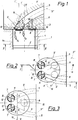
- Fig.1 eine Ausführungsform der Erfindung im Längsschnitt durch einen Zylinder einschließlich Zylinderkopf nach der Linie I-I in Fig.2,
- Fig.2 einen Schnitt nach der Linie II-II in Fig.1;
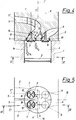
- Fig.3 eine andere Ausführung gemäß der Erfindung mit zwei Einlaßventilen und einem Auslaßventil,
- Fig.4 eine weitere Ausführungsvariante im Längsschnitt nach der Linie IV-IV in Fig.5 und
- Fig. 5 dazu einen Schnitt nach der Linie V-V in Fig.4. In den Darstellungen sind funktionsgleiche Teile mit gleichen Bezugszeichen bezeichnet.
- 1 shows an embodiment of the invention in longitudinal section through a cylinder including cylinder head along the line II in Fig.2,
- 2 shows a section along the line II-II in Fig.1;
- 3 shows another embodiment according to the invention with two inlet valves and one outlet valve,
- 4 shows another embodiment variant in longitudinal section along the line IV-IV in Fig.5 and
- 5 shows a section along the line VV in Fig.4. In the illustrations, functionally identical parts are identified by the same reference symbols.
Bei der erfindungsgemäßen Ausführung nach den Fig.1 und 2 umfaßt die Brennkraftmaschine einen Zylinderblock 1, einen hin- und hergehenden Kolben 2, einen am Zylinderblock 1 befestigten Zylinderkopf 3, sowie einen zwischen Innenwand des Zylinders 1a und dem Boden des Kolbens 2 gebildeten Brennraum 4. Die im Zylinderkopf 3 enthaltenen Einlaßkanäle 5 sowie der Auslaßkanal 6 sind so konstruiert, daß sich die Flansche an derselben Zylinderkopfseite befinden. Sind mehrere Einlaßventile 7 bzw. Auslaßventile 8 vorhanden, so sind diese so angeordnet, daß die Verbindungsgeraden der Ventilmitten der Einlaßventile 7 bzw. die Verbindungsgeraden der Ventilmitten der Auslaßventile 8 vorzugsweise parallel zur Motorlängsachse X liegen.1 and 2, the internal combustion engine comprises a
In Fig. 2 ist weiters der Bereich A der Oberfläche 5' des Einlaßkanals 5, in dem diese dem Ventilsitzring 9 des Einlaßventils 7 abgewendet ist, sowie der Bereich B der Oberfläche 5' des Einlaßkanals 5, in dem diese dem Ventilsitzring 9 des Einlaßventiles 7 zugewendet ist, eingezeichnet. Diese Bereiche A und B sind im Grundriß betrachtet, jeweils symmetrisch zur Kanalmittellinie 5'' des Einlaßkanals 5 angeordnet. Der Eintrittswinkel des Einlaßkanals 5 im Bereich A, gemessen beim Ventilsitzring 9, als Winkel zwischen der auf die Zylinderachse rechtwinkelig stehenden, einlaßseitigen Begrenzungsebene 9' des Ventilsitzringes 9 und der Tangente 13 auf die Oberfläche des Einlaßkanals 5, ist mit α bezeichnet. Der Eintrittswinkel des Einlaßkanals 5 im Bereich B, wieder gemessen beim Ventilsitzring 9, als Winkel zwischen der auf die Zylinderachse rechtwinkelig stehenden, einlaßseitigen Begrenzungsebene 9' des Ventilsitzringes 9 und der Tangente 14 auf die Oberfläche des Einlaßkanals 5, ist mit ß gekennzeichnet. Die Strömungsrichtung und die Menge des eintretenden Frischgases wird durch die Richtung und Länge der Pfeile S₁ und S₂ in Fig. 1 angedeutet. Sowohl der Bereich A als auch der Bereich B erstrecken sich über einen Winkel 11 bzw. 12 von etwa 90° bis 160°, wobei die Bereiche A und B auch unterschiedlich groß sein können. Mit 15 ist eine auf die Motorlängsebene 16 normal stehende Symetrieebene bezeichnet.2 further shows the area A of the surface 5 'of the
Die Erfindung eignet sich vorzüglich für die unterschiedlichsten Anordnungen und Anzahlen von Ein- und Auslaßventilen 9 bzw. 10.The invention is particularly suitable for a wide variety of arrangements and numbers of intake and
Die erfindungsgemäße Ausführungsform nach Fig. 3 weist zwei Einlaßventile 7 und nur ein Auslaßventil 8 auf.The embodiment according to FIG. 3 has two
Bei dem Beispiel für eine andere Ausführungsform nach Fig. 4 und 5 sind die Flansche der Einlaßkanäle 5 und des Auslaßkanals 6 an gegenüberliegenden Seiten des Zylinderkopfes 3 angeordnet. Es gelten auch hier die Voraussetzungen wie bei der Ausführung nach Fig. 1 und 2; es liegen ähnliche Strömungsverhältnisse vor.In the example of another embodiment according to FIGS. 4 and 5, the flanges of the
Versuche haben gezeigt, daß optimale Verhältnisse vorliegen, wenn der Eintrittswinkel α im Bereich A zwischen 20° und 45°, vorzugsweise bei 30°, und der Eintrittswinkel ß im Bereich B zwischen 50° und 70°, vorzugsweise bei 60°, liegt. Dadurch kann verhindert werden, daß das Frischgas auf kürzestem Wege den Brennraum durch das Auslaßventil verläßt.Experiments have shown that optimal conditions exist when the entry angle α in the area A is between 20 ° and 45 °, preferably 30 °, and the entry angle β in the area B is between 50 ° and 70 °, preferably 60 °. Thereby can be prevented that the fresh gas leaves the combustion chamber through the exhaust valve in the shortest possible way.
Claims (5)
Applications Claiming Priority (2)
| Application Number | Priority Date | Filing Date | Title |
|---|---|---|---|
| AT146/92 | 1992-01-29 | ||
| AT14692 | 1992-01-29 |
Publications (1)
| Publication Number | Publication Date |
|---|---|
| EP0554235A1 true EP0554235A1 (en) | 1993-08-04 |
Family
ID=3482753
Family Applications (1)
| Application Number | Title | Priority Date | Filing Date |
|---|---|---|---|
| EP93890002A Withdrawn EP0554235A1 (en) | 1992-01-29 | 1993-01-11 | Two stroke engine with at least one inlet and one exhaust valve per cylinder |
Country Status (1)
| Country | Link |
|---|---|
| EP (1) | EP0554235A1 (en) |
Cited By (8)
| Publication number | Priority date | Publication date | Assignee | Title |
|---|---|---|---|---|
| WO1995016113A1 (en) * | 1993-12-08 | 1995-06-15 | Koenig Kurt | Controlled two-stroke internal combustion engine |
| EP0924422A3 (en) * | 1997-12-18 | 2000-02-23 | Nissan Motor Company, Limited | Fuel direct injection spark ignition type internal combustion engine |
| EP0984149A2 (en) * | 1998-08-31 | 2000-03-08 | Honda Giken Kogyo Kabushiki Kaisha | Cylinder head structure in internal combustion engine |
| US6401702B1 (en) | 1993-12-08 | 2002-06-11 | Koenig Kurt | Controlled two-stroke internal combustion engine |
| US6880509B2 (en) | 2002-08-23 | 2005-04-19 | Avl List Gmbh | Intake manifolding for an internal combustion engine |
| AT413856B (en) * | 2002-08-23 | 2006-06-15 | Avl List Gmbh | Air intake channel arrangement for cylinder head of IC engine using tangential primary air intake channel and secondary air intake channel provided with control device for altering inlet flow rotation |
| WO2022183868A1 (en) * | 2021-03-01 | 2022-09-09 | 比亚迪股份有限公司 | Engine and vehicle with engine |
| CN117569942A (en) * | 2024-01-17 | 2024-02-20 | 潍柴动力股份有限公司 | Engine cylinder cover and engine |
Citations (3)
| Publication number | Priority date | Publication date | Assignee | Title |
|---|---|---|---|---|
| CH377584A (en) * | 1958-03-25 | 1964-05-15 | Tatra Np | Intake duct in an internal combustion engine, in particular a diesel engine |
| EP0431866A1 (en) * | 1989-12-07 | 1991-06-12 | Ricardo Group Plc | Internal combustion engines |
| EP0432950A1 (en) * | 1989-12-15 | 1991-06-19 | Ricardo Group Plc | Internal combustion engines |
-
1993
- 1993-01-11 EP EP93890002A patent/EP0554235A1/en not_active Withdrawn
Patent Citations (3)
| Publication number | Priority date | Publication date | Assignee | Title |
|---|---|---|---|---|
| CH377584A (en) * | 1958-03-25 | 1964-05-15 | Tatra Np | Intake duct in an internal combustion engine, in particular a diesel engine |
| EP0431866A1 (en) * | 1989-12-07 | 1991-06-12 | Ricardo Group Plc | Internal combustion engines |
| EP0432950A1 (en) * | 1989-12-15 | 1991-06-19 | Ricardo Group Plc | Internal combustion engines |
Cited By (14)
| Publication number | Priority date | Publication date | Assignee | Title |
|---|---|---|---|---|
| US5738050A (en) * | 1993-12-08 | 1998-04-14 | Koenig; Kurt | Controlled two-stroke internal combustion engine |
| WO1995016113A1 (en) * | 1993-12-08 | 1995-06-15 | Koenig Kurt | Controlled two-stroke internal combustion engine |
| US6401702B1 (en) | 1993-12-08 | 2002-06-11 | Koenig Kurt | Controlled two-stroke internal combustion engine |
| US6196185B1 (en) | 1997-12-18 | 2001-03-06 | Nissan Motor Co., Ltd. | Fuel direct injection spark ignition type internal combustion engine |
| EP0924422A3 (en) * | 1997-12-18 | 2000-02-23 | Nissan Motor Company, Limited | Fuel direct injection spark ignition type internal combustion engine |
| EP0984149A2 (en) * | 1998-08-31 | 2000-03-08 | Honda Giken Kogyo Kabushiki Kaisha | Cylinder head structure in internal combustion engine |
| EP0984149A3 (en) * | 1998-08-31 | 2001-01-24 | Honda Giken Kogyo Kabushiki Kaisha | Cylinder head structure in internal combustion engine |
| US6880509B2 (en) | 2002-08-23 | 2005-04-19 | Avl List Gmbh | Intake manifolding for an internal combustion engine |
| DE10338132B4 (en) * | 2002-08-23 | 2005-11-10 | Avl List Gmbh | Intake passage arrangement for an internal combustion engine |
| AT413856B (en) * | 2002-08-23 | 2006-06-15 | Avl List Gmbh | Air intake channel arrangement for cylinder head of IC engine using tangential primary air intake channel and secondary air intake channel provided with control device for altering inlet flow rotation |
| WO2022183868A1 (en) * | 2021-03-01 | 2022-09-09 | 比亚迪股份有限公司 | Engine and vehicle with engine |
| US11952957B2 (en) | 2021-03-01 | 2024-04-09 | Byd Company Limited | Engine and vehicle having the same |
| CN117569942A (en) * | 2024-01-17 | 2024-02-20 | 潍柴动力股份有限公司 | Engine cylinder cover and engine |
| CN117569942B (en) * | 2024-01-17 | 2024-04-16 | 潍柴动力股份有限公司 | Engine cylinder cover and engine |
Similar Documents
| Publication | Publication Date | Title |
|---|---|---|
| DE3625947C2 (en) | Internal combustion engine cylinder head with coolant channels | |
| DE4410686A1 (en) | Intake system for internal combustion engines | |
| DE69926142T2 (en) | INTERNAL COMBUSTION ENGINE WITH CRANKCASE FLUSHING | |
| DE19942169C2 (en) | Internal combustion engine with two intake valves per cylinder | |
| EP0554235A1 (en) | Two stroke engine with at least one inlet and one exhaust valve per cylinder | |
| DE4409750B4 (en) | Cylinder block of a liquid-cooled internal combustion engine with a magnesium housing | |
| DE3107898A1 (en) | Cross-flow combustion engine with exhaust gas recirculation system | |
| EP0819837B1 (en) | Cooling circuit of an internal combustion engine | |
| DE3020517A1 (en) | DEVICE FOR DERIVING COMBUSTION PRODUCTS FLOWING TO THE EXHAUST IN AN INTERNAL COMBUSTION ENGINE | |
| EP0204687B1 (en) | Two-stroke internal-combustion engine | |
| EP0878618A2 (en) | Water cooled cylinder block | |
| DE3806031C2 (en) | Multi-cylinder engine block for a two-stroke internal combustion engine | |
| DE69838352T2 (en) | Internal combustion engine with direct fuel injection and spark ignition | |
| DE2946017A1 (en) | EXHAUST CHANNEL FOR COMBUSTION ENGINE | |
| DE3909544C2 (en) | ||
| DE3435386A1 (en) | AIR-COOLED MULTI-CYLINDER INTERNAL COMBUSTION ENGINE | |
| DE1960071A1 (en) | Boxer engine | |
| DE19949616A1 (en) | Intake system for a cylinder head | |
| DE4012492A1 (en) | Scavenging of two-stroke IC engine - has projection on wall of inlet port which deflects air to side of cylinder | |
| EP0123101B1 (en) | Cylinder head for an air-cooled internal-combustion piston engine | |
| DE814685C (en) | Coolant supply in liquid-cooled internal combustion engines | |
| EP0598699A1 (en) | Four-stroke combustion engine | |
| DE3728176C2 (en) | Rotary slide valve for controlling the gas exchange of an internal combustion engine | |
| DE2319662C3 (en) | Cylinder for two-stroke reciprocating internal combustion engines | |
| AT402538B (en) | CYLINDER HEAD FOR A PARTLY LIQUID-COOLED DIESEL ENGINE |
Legal Events
| Date | Code | Title | Description |
|---|---|---|---|
| PUAI | Public reference made under article 153(3) epc to a published international application that has entered the european phase |
Free format text: ORIGINAL CODE: 0009012 |
|
| 17P | Request for examination filed |
Effective date: 19930518 |
|
| AK | Designated contracting states |
Kind code of ref document: A1 Designated state(s): DE ES FR GB IT SE |
|
| 17Q | First examination report despatched |
Effective date: 19940209 |
|
| STAA | Information on the status of an ep patent application or granted ep patent |
Free format text: STATUS: THE APPLICATION HAS BEEN WITHDRAWN |
|
| 18W | Application withdrawn |
Withdrawal date: 19940824 |