EP0553997A2 - Jonction étanche et joint pour des outils de puits - Google Patents
Jonction étanche et joint pour des outils de puits Download PDFInfo
- Publication number
- EP0553997A2 EP0553997A2 EP93300367A EP93300367A EP0553997A2 EP 0553997 A2 EP0553997 A2 EP 0553997A2 EP 93300367 A EP93300367 A EP 93300367A EP 93300367 A EP93300367 A EP 93300367A EP 0553997 A2 EP0553997 A2 EP 0553997A2
- Authority
- EP
- European Patent Office
- Prior art keywords
- seal
- arms
- annular
- members
- sealing
- Prior art date
- Legal status (The legal status is an assumption and is not a legal conclusion. Google has not performed a legal analysis and makes no representation as to the accuracy of the status listed.)
- Ceased
Links
Images
Classifications
-
- F—MECHANICAL ENGINEERING; LIGHTING; HEATING; WEAPONS; BLASTING
- F16—ENGINEERING ELEMENTS AND UNITS; GENERAL MEASURES FOR PRODUCING AND MAINTAINING EFFECTIVE FUNCTIONING OF MACHINES OR INSTALLATIONS; THERMAL INSULATION IN GENERAL
- F16J—PISTONS; CYLINDERS; SEALINGS
- F16J15/00—Sealings
- F16J15/02—Sealings between relatively-stationary surfaces
- F16J15/06—Sealings between relatively-stationary surfaces with solid packing compressed between sealing surfaces
- F16J15/08—Sealings between relatively-stationary surfaces with solid packing compressed between sealing surfaces with exclusively metal packing
- F16J15/0887—Sealings between relatively-stationary surfaces with solid packing compressed between sealing surfaces with exclusively metal packing the sealing effect being obtained by elastic deformation of the packing
-
- E—FIXED CONSTRUCTIONS
- E21—EARTH DRILLING; MINING
- E21B—EARTH DRILLING, e.g. DEEP DRILLING; OBTAINING OIL, GAS, WATER, SOLUBLE OR MELTABLE MATERIALS OR A SLURRY OF MINERALS FROM WELLS
- E21B34/00—Valve arrangements for boreholes or wells
- E21B34/06—Valve arrangements for boreholes or wells in wells
-
- Y—GENERAL TAGGING OF NEW TECHNOLOGICAL DEVELOPMENTS; GENERAL TAGGING OF CROSS-SECTIONAL TECHNOLOGIES SPANNING OVER SEVERAL SECTIONS OF THE IPC; TECHNICAL SUBJECTS COVERED BY FORMER USPC CROSS-REFERENCE ART COLLECTIONS [XRACs] AND DIGESTS
- Y10—TECHNICAL SUBJECTS COVERED BY FORMER USPC
- Y10S—TECHNICAL SUBJECTS COVERED BY FORMER USPC CROSS-REFERENCE ART COLLECTIONS [XRACs] AND DIGESTS
- Y10S285/00—Pipe joints or couplings
- Y10S285/917—Metallic seals
Definitions
- This invention relates to a sealed joint and seal for use in oil and gas well tools and the like, and more particularly to seals for sliding sleeve-type closures designed to maintain a sealing connection for relatively long time periods, such as the life of the well.
- Sealing of components in oil and gas wells is of critical importance, both during the operation of downhole tools and for use in portions of the tools which remain in the well after completion, testing and production.
- well apparatus with sliding closures frequently must be sealed during operation, and this sealing engagement must be maintained substantially indefinitely.
- Prior art seals such as elastomeric seals can have problems over time in that the elastomer may lose resiliency or shape memory which is necessary for the seal to oppose the imposed squeeze forces thereon. This is a particular problem with exposure to downhole chemical and higher temperature environments of oil and gas wells for long periods of time. A seal is therefore required that remains operative in these types of environments.
- Metal-to-metal seals have been developed because they are not affected by the chemicals and temperatures that are usually encountered. However, metal-to-metal seals are normally only used as static seals or as safety backup seals to standard elastomeric rotational or sliding seals because they have not been proven to be particularly suitable for use in dynamic sealing applications.
- One factor in the use of metal-to-metal seals is that the contacted sealing surfaces must be machined particularly smoothly and be free of pits and scratches so that a positive seal may be maintained. Damage to these surfaces can be caused byt galling and scratching as the metal seal moves across the seal surface, and in such cases leakage is likely.
- a sealed joint comprising a first member having a sealing surface defining first and second diameters; a second member having a sealing surface defining first and second diameters, said first and second members being relatively movable between first and second positions; and a seal disposed between said first and second members and comprising a body portion defining a groove therein; first and second annular arms extending from a side of said body portion and defining an annular groove therebetween; third and fourth annular arms extending from an opposite side of said body portion from said first and second annular arms and defining an annular groove therebetween; first, second, third and fourth lips on said first, second, third and fourth arms, respectively; wherein said first and third lips are spaced from said first diameter of said sealing surface of said first member when said first and second members are in said first position; said first and third lips are adapted for sealing engagement with said second diameter of said sealing surface of said first member when said first and second members are in said second position; and said second and fourth lips are adapted for sealing engagement with
- the invention also includes a seal assembly for sealing between sealing surfaces on first and second members which define an annular cavity therebetween comprising a seal disposed in said cavity, said seal comprising a body portion; a pair of annular arms extending from said body portion and defining a groove therebetween; and a lip on each of said arms, each lip being adapted for sealing engagement with the sealing surfaces on one of the first and second members; and a pusher ring disposed adjacent to said seal and having a portion extending therefrom into said groove such that longitudinal engagement by said lips with either of said first and second members is prevented.
- the invention further includes a gas or oil well tool including a seal or sealed joint of the invention.
- the present invention may be described as an apparatus for sealing between a pair of relatively slidable or movable members.
- the apparatus comprises a body portion disposable between a pair of members, a pair of annular arms extending from a side of the body portion, another pair of annular arms extending from an opposite side of the body portion, and a lip disposed on each of the arms adapted for engaging one of the members such that the first pair of arms are deflected toward one another and the second pair of arms are deflected toward one another.
- the two pairs of arms provide sealing in both directions.
- the arms are preferably integrally formed with the body portion.
- the apparatus further comprises elastomeric sealing means for dynamically sealing between the members as the members are relatively moved.
- the body portion preferably defines a groove therein, and the dynamic sealing means is characterized by an elastomeric seal disposed in the groove.
- the present invention is characterized as a seal assembly for sealing between relatively movable first and second members, the first and second members defining a cavity therebetween.
- the seal assembly comprises a seal disposed in the cavity with a pusher ring disposed adjacent thereto.
- the seal comprises a body portion, a pair of annular arms extending from the body portion and defining a groove therebetween, and a lip on each of the arms. Each lip is adapted for sealing engagement with the sealing surfaces on one of the first and second members.
- the pusher ring has a portion extending therefrom into the groove such that longitudinal engagement by the lips with either of the first and second members is prevented.
- the seal may further comprise a second pair of annular arms extending from an opposite side of the body portion from the first mentioned pair of arms, and a lip on each of the second pair of arms for sealing engagement with the sealing surfaces of one of the first and second members.
- a second pusher ring is disposed on an opposite side of the seal and has a portion extending into the groove between the second pair of arms such that longitudinal engagement with the lips on the second pair of arms with the first and second members is prevented.
- the seal assembly further comprises clamping means for clampingly engaging one of the pusher rings and thereby clamping the seal and the pusher rings to one of the first and second members.
- the apparatus of the present invention further includes a sealed joint comprising a first member having a sealing surface defining first and second diameters, a second member having a sealing surface defining first and second diameters, the first and second diameters being relatively movable between first and second positions, and a seal defined between the first and second members.
- the seal comprises a body portion defining a groove therein, first and second annular arms extending from a side of the body portion and defining an annular groove therebetween, and third and fourth annular arms extending from an opposite side of the body portion from the first and second annular arms and defining an annular groove therebetween.
- First, second, third and fourth lips are disposed on the first, second, third and fourth arms, respectively.
- the first and third lips are spaced from the first diameter of the sealing surface of the first member when the first and second members are in the first position.
- the first and third lips are adapted for sealing engagement with the second diameter of the sealing surface of the first member when the first and second members are in the second position.
- the second and fourth lips are adapted for sealing engagement with the second diameter of the sealing surface of the second member.
- the seal in the seal joint further comprises an elastomeric sealing element disposed in the groove and adapted for sealing engagement with the first diameter of the sealing surface of the first member when the first and second members are in the first position and for tighter sealing engagement with the second diameter of the sealing surface of the first member when the first and second members are in the second position.
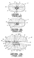
- FIG. 1 shows a prior art elastomeric seal.
- FIG. 2 shows the prior art seal of Fig. 1 with a differential pressure applied thereacross.
- FIG. 3 illustrates a prior art metal-to-metal seal.
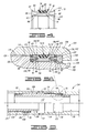
- FIG. 4 shows an uninstalled first embodiment of seal of the present invention, by way of example only.
- FIG. 5 shows the first embodiment seal installed in a sliding joint.
- FIG. 5A is an enlarged detail of the seal shown in Fig. 5.
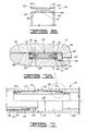
- FIG. 6 illustrates an uninstalled second embodiment of the seal of the present invention, by way of example only.
- FIG. 7 shows the second embodiment seal installed in a sliding joint.
- FIG. 7A is an enlarged detail of the seal shown in Fig. 7.
- Joint 10 comprises a first member 12 adjacent to a second member 14 with an elastomeric sealing means, such as seal 16, disposed therebetween and providing sealing engagement.
- seal 16 is disposed in a groove 18, and first and second members 12 and 14 have a slight gap 20 therebetween.
- Seal 16 is made of any of a variety of elastomeric materials. These elastomeric materials are commonly, and almost exclusively, used for seals designed to hold differential fluid pressures because the elastomeric materials have an inherent property that makes them ideal for this purpose. As illustrated in Fig. 1, seal 16 is an O-ring which, when placed in groove 18 between first and second members 12 and 14, has an imposed squeeze thereon as indicated by arrows 22. The elastomeric material has an inherent resiliency that causes it to oppose the squeeze force with an equal force. This provides the force necessary to hold the initial differential pressure.
- the elastomeric material loses its resiliency or shape memory that allows for it to oppose the imposed squeeze force, the initial sealing action may be lost as well. This will sometimes happen with exposure of seal 16 to downhole chemical and temperature environments of oil and gas wells for long periods of time. That is, the chemical and temperature environment may cause the elastomeric material of seal 16 to lose its resiliency. Also, even in a relatively non-hostile environment, some elastomeric materials may age-harden and lose their resiliency over a period of time anyway.
- FIG. 3 a prior art seal joint 30 is shown in which a first member 32 is positioned adjacent to a second member 34 and a metal-to-metal seal 36 is disposed therebetween for providing sealing engagement.
- First member 34 has a first diameter 38 and a second diameter 40 thereon with an annular shoulder 39 extending therebetween. As illustrated, seal 36 is disposed on diameter 38 adjacent to shoulder 39. A retainer ring 41 holds seal 36 in place.
- First member 32 has a surface formed by a first diameter 42 and a second diameter 44 with a chamfer 46 extending therebetween.
- First diameter 42 and surface 40 define a first gap 48 therebetween, and second diameter 44 and surface 40 define a second gap 50 therebetween. It will be seen that gap 48 is larger than gap 50 and that seal 36 engages second diameter 44 on first member 32 when in the sealing position shown in FIG. 3.
- Seal joint 30 is assembled by first positioning seal 36 and retainer ring 41 in place and sliding second member 34 to the right with respect to first member 32.
- First diameter 42 is sized such that seal 36 does not engage first diameter 42. That is, seal 36 does not engage first member 32 until it comes in contact with chamfer 46 which gradually compresses the seal until it passes into second diameter 44.
- a first lip 52 is sealingly engaged with second diameter 44 of first member 32, and a second lip 54 is engaged with diameter 38 in second member 34.
- Seal 36 has a main body portion 56 with a first annular arm 58 and a second annular arm 60 extending therefrom.
- First lip 52 is on the end of arm 58 opposite from body 56, and second lip 54 is on second arm 60 opposite from body 56.
- a substantially V-shaped annular groove 62 is defined between arms 58 and 60.
- Such metal-to-metal seals are sometimes used in downhole equipment for oil and gas wells because they are not affected by the chemicals and temperatures that are usually encountered in such wells. However, they are generally only used as static seals or as safety backups to standard elastomeric rotational seals because they have not proven to be particularly suitable for use in dynamic sealing applications.
- metal-to-metal seals are unsatisfactory for dynamic seal applications.
- This high spring force causes extremely high frictional forces that hinder the rotational or reciprocating movement of a dynamic seal.
- the contacting sealing surfaces, second diameter 44 on first member 32 and diameter 38 on second member 34 must be machined to be extremely smooth and free of pits and scratches so that a positive seal can be maintained. Damage to these surfaces, particularly to second diameter 44 and lip 52, can be caused by galling and scratching as the high spring force metal seal 36 moves across the sealing surface of second diameter 44. Obviously, when the sealing surface is damaged, the metal-to-metal seal is not able to compensate.
- FMC-Wellhead Equipment Division uses a thermally activated metal seal as a backup to a standard elastomeric operating stem seal because the frictional force of a metal-to-metal seal is too great to allow hand operation of the valve-operated stem.
- the metal seal is activated by increasing temperature when the valve is exposed to high thermal conditions, such as a wellhead fire.
- Seal 70 includes a metal-to-metal seal portion 72 and elastomeric in-transit or dynamic seal portion 74.
- Metal-to-metal seal portion 72 preferably comprises a central body portion 78 defining a large groove 80 in which dynamic seal 74 is disposed.
- Seal 74 preferably has a curved, annular groove 82 therein.
- An annular, V-shaped groove 88 is defined between first and second arms 84 and 86.
- First arm 84 has an annular first lip 90 thereon, and second arm 86 has an annular second lip 92 thereon.
- Third and fourth arms 94 and 96 define an annular, V-shaped groove 98 therebetween.
- Third arm 94 has an annular third lip 100 thereon, and fourth arm 96 has an annular fourth lip 102 thereon.
- metal-to-metal seal portion 72 is symmetric so that first and third arms 84 and 94 are substantially identical, and second and fourth arms 86 and 96 are substantially identical.
- Sealed joint 104 includes a first member 106 and a second member 108 which are relatively slidable.
- the lower half of FIG. 5 shows second member 108 in a first, open position within first member 106 in which a port 110 is in communication with a central opening 112 through joint 104.
- the upper half of FIG. 5 shows first and second members 106 and 108 in a closed, sealed position in which port 110 and central opening 112 are no longer in communication.
- first member 106 is an outer member
- second member 108 is an inner member
- second member 108 slides within first member 106.
- sealed joint 104 can follow many configurations, including one in which the outer member slides with respect to the inner member.
- seal 70 within sealed joint 104 will be discussed.
- First member 106 has a first bore 114, second bore 116 and third bore 118 which are progressively smaller.
- a chamfer 120 extends between first and second bores 114 and 116.
- An annular shoulder 122 extends between second bore 116 and third bore 118.
- Second member 108 has a first outside diameter 124, second outside diameter 126 and third outside diameter 128 which are progressively smaller.
- An annular shoulder 130 extends between first outside diameter 124 and second outside diameter 126.
- a chamfer 131 and a threaded surface 132 are disposed between second outside diameter 126 and third outside diameter 128.
- Chamfer 131 prevents damage to lips 92 and 102 as seal 70 is installed.
- first and second bores 114 and 116 in first member 106 are larger than first outside diameter 124 on second member 108. Also, third bore 118 in first member 106 is larger than third outside diameter 128 on second member 108.
- Pusher rings 134 and 136 are disposed on opposite sides of seal 72.
- Pusher ring 134 has a flange 138 adjacent to shoulder 130 and a tapered portion 140 which extends into groove 88 and bears against metal-to-metal seal portion 72.
- pusher ring 136 has a flange 142 and a tapered portion 144 which extends into groove 98.
- a lock ring 146 is engaged with thread 132 on second member 108 so that it bears against flange 142 of pusher ring 136. It will thus be seen that seal 70 is clamped longitudinally against shoulder 130 between pusher rings 134 and 136 by lock ring 146.
- seal 70 is initially within first bore 114 in first member 106.
- Seal 70 is preferably constructed such that lips 90 and 100 on metal-to-metal seal portions 72 do not engage first bore 114. However, elastomeric seal portion 74 does sealingly engage first bore 114.
- Lock ring 146 also acts as a stop which engages shoulder 122 in first member 106 when sealed joint 104 is moved to its closed position.
- seal 150 includes only a metal-to-metal seal portion with no elastomeric portions directly engaged therewith.
- second embodiment seal 150 is substantially the same as first embodiment seal 70 omitting dynamic seal portion 74.
- seal 150 may be referred to as a metal-to-metal seal portion 150 which preferably comprises a central body portion 152 with annular first, second, third and fourth arms 154, 156, 158 and 160 extending therefrom. Each arm has a corresponding first, second, third and fourth lip 162, 164, 166 and 168 thereon.
- seal 150 is symmetric so that first and third arms 154 and 158 are substantially identical, and second and fourth arms 156 and 160 are substantially identical.
- Sealed joint 170 includes a first member 172 and a second member 174 which are relatively slidable.
- the lower half of FIG. 7 shows second member 174 in a first, open position within first member 172 in which a port 176 is in communication with a central opening 178 through joint 170.
- the upper half of FIG. 7 shows first and second members 172 and 174 in a closed, sealed position in which port 176 and central opening 178 are no longer in communication.
- first member 172 is an outer member
- second member 174 is an inner member
- second member 174 slides within first member 172.
- sealed joint 170 can follow many configurations, including one in which the outer member slides with respect to the inner member.
- First member 172 has a first bore 180 and a second bore 182 which is smaller than the first bore.
- An annular shoulder 184 extends between first bore 180 and second bore 182.
- Second member 174 has a first outside diameter 186, second outside diameter 188 and third outside diameter 190 which are progressively smaller.
- An annular shoulder 192 extends between first outside diameter 186 and second outside diameter 188.
- a chamfer 193 and a threaded surface 194 are disposed between second outside diameter 188 and third outside diameter 190.
- Chamfer 193 prevents damage to lips 164 and 168 as seal 150 is installed.
- first bore 180 in first member 172 is larger than first outside diameter 186 on second member 174. Also, second bore 182 in first member 172 is larger than third outside diameter 190 on second member 174.
- a pair of pusher rings 196 and 198 are disposed on opposite sides of seal 150.
- Pusher rings 196 and 198 are substantially identical to pusher rings 134 and 136 in the first embodiment.
- a lock ring 200 is engaged with thread 194 on second member 174 so that it bears against pusher ring 198. It will thus be seen that seal 150 is clamped longitudinally against shoulder 192 between pusher rings 196 and 198 by lock ring 200.
- seal 150 slides with in first bore 180 in first member 172. That is, first and third lips 162 and 166 slide along first bore 180. Second and fourth lips 164 and 168 remain in engagement with second outside diameter 188 on second member 174.
- seal 150 will provide consistent sealing engagement as second member 174 slides within first member 172.
- lock ring 200 engages shoulder 184, thereby acting as a stop when sealed joint 170 is in its closed position, seal 174 will maintain its sealing engagement substantially indefinitely in the manner of previous metal-to-metal seals because it is not susceptible to attack by heat or chemicals.
Landscapes
- Engineering & Computer Science (AREA)
- General Engineering & Computer Science (AREA)
- Life Sciences & Earth Sciences (AREA)
- Geology (AREA)
- Mining & Mineral Resources (AREA)
- Environmental & Geological Engineering (AREA)
- Fluid Mechanics (AREA)
- General Life Sciences & Earth Sciences (AREA)
- Geochemistry & Mineralogy (AREA)
- Physics & Mathematics (AREA)
- Mechanical Engineering (AREA)
- Quick-Acting Or Multi-Walled Pipe Joints (AREA)
- Gasket Seals (AREA)
Applications Claiming Priority (2)
| Application Number | Priority Date | Filing Date | Title |
|---|---|---|---|
| US823523 | 1992-01-21 | ||
| US07/823,523 US5246236A (en) | 1992-01-21 | 1992-01-21 | Seal for long-time exposures in oil and gas well tools |
Publications (2)
| Publication Number | Publication Date |
|---|---|
| EP0553997A2 true EP0553997A2 (fr) | 1993-08-04 |
| EP0553997A3 EP0553997A3 (en) | 1993-10-06 |
Family
ID=25239010
Family Applications (1)
| Application Number | Title | Priority Date | Filing Date |
|---|---|---|---|
| EP19930300367 Ceased EP0553997A3 (en) | 1992-01-21 | 1993-01-20 | Sealed joint and seal for well tools |
Country Status (2)
| Country | Link |
|---|---|
| US (1) | US5246236A (fr) |
| EP (1) | EP0553997A3 (fr) |
Cited By (4)
| Publication number | Priority date | Publication date | Assignee | Title |
|---|---|---|---|---|
| WO2008020759A1 (fr) * | 2006-07-14 | 2008-02-21 | Peak Well Solutions As | Dispositif de fermeture étanche |
| EP2047166A1 (fr) * | 2006-08-03 | 2009-04-15 | Welldynamics, Inc. | Scellement métal-métal pour outils de fond de puits |
| EP2238380A1 (fr) * | 2008-02-04 | 2010-10-13 | Welldynamics, Inc. | Joint d'étanchéité métal-métal composite excité |
| GB2474774A (en) * | 2009-10-22 | 2011-04-27 | Smith International | Downhole Metal to Metal Seal and Ratcheting Retention Device |
Families Citing this family (42)
| Publication number | Priority date | Publication date | Assignee | Title |
|---|---|---|---|---|
| US5364110A (en) * | 1992-12-11 | 1994-11-15 | Halliburton Company | Downhole tool metal-to-metal seal |
| US5439589A (en) * | 1994-05-09 | 1995-08-08 | Trafalgar House Inc. | Sealing means for slide plate screen changer |
| US5456314A (en) * | 1994-06-03 | 1995-10-10 | Abb Vetco Gray Inc. | Wellhead annulus seal |
| US5791665A (en) | 1995-06-07 | 1998-08-11 | Gbg Mayer Inc. | Roller skate with brake |
| US5755287A (en) * | 1996-04-03 | 1998-05-26 | Fmc Corporation | Sealing assembly for subsea wellheads |
| ATE250734T1 (de) * | 1996-08-29 | 2003-10-15 | Flexitallic Investments Inc | Dichtungsring und verfahren zum abdichten eines spalts |
| DE19702806C1 (de) * | 1997-01-27 | 1998-08-06 | Troester Maschf Paul | Verfahren und Vorrichtung zum Abdichten eines Ringspaltes zwischen zwei Dichtflächen von Maschinenteilen, insbesondere an Extrusionsmaschinen |
| AU2002357086A1 (en) * | 2001-12-07 | 2003-06-23 | Nobel Biocare Ab | Healing abutment |
| US6869079B2 (en) * | 2002-02-15 | 2005-03-22 | Fmc Technologies, Inc. | Stackable metallic seal and method of using same |
| US20030155721A1 (en) * | 2002-02-15 | 2003-08-21 | Zheng Qiu Shi | Metal-to-metal seal and method of making same |
| AU2003300196B2 (en) * | 2003-01-03 | 2009-03-12 | Nobel Biocare Services Ag | Dental implant system |
| US20050067794A1 (en) * | 2003-09-30 | 2005-03-31 | Philippe Gambier | Thermoplastic seal and method |
| US7770899B1 (en) * | 2004-06-21 | 2010-08-10 | Aker Subsea Inc. | Pressure actuated seal carrier |
| US20060220326A1 (en) * | 2005-03-30 | 2006-10-05 | Andrew Corporation | Multilobe gasket and sealing groove |
| DE112006001582B4 (de) * | 2005-06-14 | 2017-12-07 | Parker-Hannifin Corp. | Dichtungsbaueinheit und Fluidkupplung |
| US20070013146A1 (en) * | 2005-07-14 | 2007-01-18 | Gariepy James A | Sealing ring and method |
| US7510019B2 (en) * | 2006-09-11 | 2009-03-31 | Schlumberger Technology Corporation | Forming a metal-to-metal seal in a well |
| US7559366B2 (en) * | 2006-12-07 | 2009-07-14 | Vetco Gray Inc. | Flex-lock metal seal system for wellhead members |
| US7614447B2 (en) * | 2007-04-26 | 2009-11-10 | Vetco Gray Inc. | System, method, and apparatus for energizable metal seals in well heads |
| GB2468075B (en) * | 2007-11-05 | 2011-03-23 | Cameron Int Corp | Self-energizing annular seal |
| US8205890B2 (en) * | 2008-07-08 | 2012-06-26 | Worldwide Oilfield Machine, Inc. | Resilient high pressure metal-to-metal seal and method |
| AU2009283907C1 (en) * | 2008-08-19 | 2013-11-21 | Aker Solutions Inc. | Tubing hanger seal |
| US8672096B2 (en) | 2008-09-04 | 2014-03-18 | Fox Factory, Incorporated | Methods and apparatus for lubricating suspension components |
| US8146670B2 (en) * | 2008-11-25 | 2012-04-03 | Vetco Gray Inc. | Bi-directional annulus seal |
| US8561995B2 (en) * | 2009-06-30 | 2013-10-22 | Vetco Gray Inc. | Metal-to-metal annulus seal arrangement |
| JP5842285B2 (ja) * | 2009-08-26 | 2016-01-13 | TOKiエンジニアリング株式会社 | メタルシールリング及び該メタルシールリングを用いた導管装置 |
| US8393400B2 (en) * | 2009-11-25 | 2013-03-12 | Vetco Gray Inc. | Metal-to-metal seal with wiper element and wellhead system incorporating same |
| DE102010001979A1 (de) * | 2009-12-09 | 2011-06-16 | Robert Bosch Gmbh | Anordnung und Verfahren zur Abdichtung eines Fügebereichs zwischen einem ersten Fügepartner und einem zweiten Fügepartner |
| GB0921634D0 (en) * | 2009-12-10 | 2010-01-27 | Artificial Lift Co Ltd | Seal,assembly and method,particularly for downhole electric cable terminations |
| US9958100B2 (en) | 2010-10-15 | 2018-05-01 | Swagelok Company | Push to connect conduit fitting with ferrule |
| US9010725B2 (en) * | 2011-12-21 | 2015-04-21 | Vetco Gray Inc. | Valve vented redundant stem seal system |
| US9611712B2 (en) * | 2012-02-09 | 2017-04-04 | Onesubsea Ip Uk Limited | Lip seal |
| US8894072B2 (en) * | 2012-06-04 | 2014-11-25 | Wayne Alan Wolf | Barrier seal |
| US20140183393A1 (en) | 2012-12-31 | 2014-07-03 | Vetco Gray Inc. | Multi-valve stem seal assembly for a gate valve |
| EP3060839B1 (fr) | 2013-10-24 | 2020-03-18 | Swagelok Company | Connecteur rapide pour conduits |
| US9551420B2 (en) * | 2014-09-12 | 2017-01-24 | American Seal And Engineering Company, Inc. | Sealing ring |
| EP3286476B1 (fr) | 2015-04-23 | 2019-10-02 | Swagelok Company | Raccord de conduit de type pousser pour connecter |
| US10458582B2 (en) * | 2015-04-23 | 2019-10-29 | Swagelok Company | Single action push to connect conduit fitting with colleting |
| GB2558447B (en) * | 2015-09-23 | 2019-12-11 | Weatherford Tech Holdings Llc | Downhole seal |
| US11105451B2 (en) * | 2017-07-07 | 2021-08-31 | Eaton Intelligent Power Limited | Heat transfer interruption for improved fire resistance/proof performance |
| SG11202102873WA (en) * | 2018-09-25 | 2021-04-29 | Schlumberger Technology Bv | Piston load ring seal configurations |
| US11781688B2 (en) | 2019-04-01 | 2023-10-10 | Swagelok Company | Push to connect conduit fitting assemblies and arrangements |
Citations (8)
| Publication number | Priority date | Publication date | Assignee | Title |
|---|---|---|---|---|
| US3288472A (en) * | 1963-07-01 | 1966-11-29 | Regan Forge & Eng Co | Metal seal |
| US3290047A (en) * | 1963-02-11 | 1966-12-06 | North American Aviation Inc | Relief seal with dual sealing surfaces |
| US3378269A (en) * | 1965-01-27 | 1968-04-16 | Armco Steel Corp | Metal-to-metal seal devices |
| FR1563153A (fr) * | 1968-02-28 | 1969-04-11 | ||
| US4129184A (en) * | 1977-06-27 | 1978-12-12 | Del Norte Technology, Inc. | Downhole valve which may be installed or removed by a wireline running tool |
| GB2121090A (en) * | 1982-06-01 | 1983-12-14 | Camco Inc | Well safety valve |
| GB2202013A (en) * | 1987-03-13 | 1988-09-14 | Heat Transfer Technology | Ring seal |
| GB2235938A (en) * | 1989-08-31 | 1991-03-20 | British Petroleum Co Plc | Annulus safety valve |
Family Cites Families (25)
| Publication number | Priority date | Publication date | Assignee | Title |
|---|---|---|---|---|
| US2470925A (en) * | 1946-01-16 | 1949-05-24 | Crane Co | Piston seal for flush valves |
| US3047300A (en) * | 1959-07-01 | 1962-07-31 | Lockheed Aircraft Corp | Metal sealing assembly |
| US3288222A (en) * | 1964-03-11 | 1966-11-29 | Schlumberger Well Surv Corp | Progressively expanded packing element for a bridge plug |
| US3387656A (en) * | 1966-01-11 | 1968-06-11 | Halliburton Co | Well casing seals |
| US3387661A (en) * | 1966-01-11 | 1968-06-11 | Halliburton Co | Well casing seals |
| US3489098A (en) * | 1968-03-18 | 1970-01-13 | Halliburton Co | Reciprocating pump having an improved seal and method of manufacture therefor |
| US3599490A (en) * | 1969-07-11 | 1971-08-17 | Halliburton Co | Safety seal for direct reading flow meter |
| DE2346332A1 (de) * | 1973-09-14 | 1975-03-27 | Babcock & Wilcox Ag | Dichtung fuer den verschluss eines druckbehaelters |
| US4131287A (en) * | 1977-07-11 | 1978-12-26 | Exxon Production Research Company | Annular seal |
| US4178020A (en) * | 1977-12-15 | 1979-12-11 | Big-Inch Marine Systems, Inc. | Locking slip joint and method of use |
| US4315543A (en) * | 1979-08-10 | 1982-02-16 | Halliburton Company | Seal system for wellhead isolation tool diffuser |
| US4471965A (en) * | 1982-05-05 | 1984-09-18 | Fmc Corporation | High-pressure fire-resistant metal seal |
| US4477085A (en) * | 1983-02-24 | 1984-10-16 | Gray Tool | Fire resistant connections embodying heat transfer means |
| US4477091A (en) * | 1983-02-24 | 1984-10-16 | Gray Tool Company | Fire resistant connections and U-like sealing means therefor |
| US4510960A (en) * | 1983-09-30 | 1985-04-16 | Fmc Corporation | Valve stem-to-bonnet backseat |
| US4452462A (en) * | 1983-10-06 | 1984-06-05 | Gray Tool Company | Temperature resistant joint packing with E-shaped spring seal |
| US4474382A (en) * | 1984-02-21 | 1984-10-02 | Halliburton Company | Unitized seal carrier assembly for reciprocating shaft |
| US4478423A (en) * | 1984-04-18 | 1984-10-23 | Halliburton Company | Oil seal and unitized seal carrier for reciprocating shaft |
| US4613159A (en) * | 1984-10-26 | 1986-09-23 | Halliburton Company | Pressure-assisted dynamic seal apparatus |
| US4787642A (en) * | 1987-04-27 | 1988-11-29 | Seaboard Wellhead, Inc. | X-shaped high pressure sealing structure |
| US4766956A (en) * | 1987-05-07 | 1988-08-30 | Cameron Iron Works Usa, Inc. | Wellhead annular seal |
| US4815770A (en) * | 1987-09-04 | 1989-03-28 | Cameron Iron Works Usa, Inc. | Subsea casing hanger packoff assembly |
| US4796858A (en) * | 1987-10-01 | 1989-01-10 | Halliburton Company | Dual seal valve |
| US4823871A (en) * | 1988-02-24 | 1989-04-25 | Cameron Iron Works Usa, Inc. | Hanger and seal assembly |
| US5044672A (en) * | 1990-03-22 | 1991-09-03 | Fmc Corporation | Metal-to-metal sealing pipe swivel joint |
-
1992
- 1992-01-21 US US07/823,523 patent/US5246236A/en not_active Expired - Fee Related
-
1993
- 1993-01-20 EP EP19930300367 patent/EP0553997A3/en not_active Ceased
Patent Citations (8)
| Publication number | Priority date | Publication date | Assignee | Title |
|---|---|---|---|---|
| US3290047A (en) * | 1963-02-11 | 1966-12-06 | North American Aviation Inc | Relief seal with dual sealing surfaces |
| US3288472A (en) * | 1963-07-01 | 1966-11-29 | Regan Forge & Eng Co | Metal seal |
| US3378269A (en) * | 1965-01-27 | 1968-04-16 | Armco Steel Corp | Metal-to-metal seal devices |
| FR1563153A (fr) * | 1968-02-28 | 1969-04-11 | ||
| US4129184A (en) * | 1977-06-27 | 1978-12-12 | Del Norte Technology, Inc. | Downhole valve which may be installed or removed by a wireline running tool |
| GB2121090A (en) * | 1982-06-01 | 1983-12-14 | Camco Inc | Well safety valve |
| GB2202013A (en) * | 1987-03-13 | 1988-09-14 | Heat Transfer Technology | Ring seal |
| GB2235938A (en) * | 1989-08-31 | 1991-03-20 | British Petroleum Co Plc | Annulus safety valve |
Cited By (11)
| Publication number | Priority date | Publication date | Assignee | Title |
|---|---|---|---|---|
| WO2008020759A1 (fr) * | 2006-07-14 | 2008-02-21 | Peak Well Solutions As | Dispositif de fermeture étanche |
| EP2041392A1 (fr) * | 2006-07-14 | 2009-04-01 | Peak Well Solutions AS | Dispositif de fermeture étanche |
| EP2041392A4 (fr) * | 2006-07-14 | 2014-08-27 | Peak Well Solutions As | Dispositif de fermeture étanche |
| EP2047166A1 (fr) * | 2006-08-03 | 2009-04-15 | Welldynamics, Inc. | Scellement métal-métal pour outils de fond de puits |
| EP2047166A4 (fr) * | 2006-08-03 | 2012-06-06 | Welldynamics Inc | Scellement métal-métal pour outils de fond de puits |
| US9033054B2 (en) | 2006-08-03 | 2015-05-19 | Welldynamics, Inc. | Metal to metal seal for downhole tools |
| EP2238380A1 (fr) * | 2008-02-04 | 2010-10-13 | Welldynamics, Inc. | Joint d'étanchéité métal-métal composite excité |
| EP2238380A4 (fr) * | 2008-02-04 | 2014-06-04 | Welldynamics Inc | Joint d'étanchéité métal-métal composite excité |
| GB2474774A (en) * | 2009-10-22 | 2011-04-27 | Smith International | Downhole Metal to Metal Seal and Ratcheting Retention Device |
| GB2474774B (en) * | 2009-10-22 | 2012-02-29 | Smith International | A downhole tool |
| US8607861B2 (en) | 2009-10-22 | 2013-12-17 | Smith International, Inc. | Metal-to-metal seal with retention device |
Also Published As
| Publication number | Publication date |
|---|---|
| EP0553997A3 (en) | 1993-10-06 |
| US5246236A (en) | 1993-09-21 |
Similar Documents
| Publication | Publication Date | Title |
|---|---|---|
| US5246236A (en) | Seal for long-time exposures in oil and gas well tools | |
| US4630636A (en) | Actuator with nonelastomeric seal | |
| US4930791A (en) | Plastic bore seal | |
| US6561521B2 (en) | Metal-to-metal seal with soft metal insert | |
| US6966537B2 (en) | Valve with seat assembly | |
| US4451047A (en) | Seal | |
| US6361049B1 (en) | Recessed groove/seal surface for seal effectiveness | |
| US6173964B1 (en) | Seal assembly with backup elements having coil springs positioned therein | |
| US4433847A (en) | Conduit sealing system | |
| US4262690A (en) | High pressure stem packing for gate valves | |
| US20020036279A1 (en) | Valve with seat assembly | |
| JPS6213870A (ja) | 弁棒パッキング組立体 | |
| US4743033A (en) | Dynamic seal assembly for piston and cylinder operating in subterranean wells | |
| US5727775A (en) | Gate valve with dual seal rings on a unitary seat ring | |
| JPS5828082A (ja) | シ−ル装置 | |
| US4486002A (en) | Combined metallic and flexible non-metallic pressure seal | |
| CA2486703A1 (fr) | Joint d'etancheite haute pression et haute temperature destine a etre utilise en fond de puits | |
| EP0024424A1 (fr) | Presse etoupe et methode | |
| US5364110A (en) | Downhole tool metal-to-metal seal | |
| US10180188B2 (en) | Multi-material seal with lip portions | |
| US4531749A (en) | Circular seal with integral backup rings | |
| US4109716A (en) | Seal | |
| US7770899B1 (en) | Pressure actuated seal carrier | |
| US4483545A (en) | Fire resistant connections and double ribbed sealing means therefor | |
| EP0392470B1 (fr) | Joint pour alésage en matière plastique |
Legal Events
| Date | Code | Title | Description |
|---|---|---|---|
| PUAI | Public reference made under article 153(3) epc to a published international application that has entered the european phase |
Free format text: ORIGINAL CODE: 0009012 |
|
| AK | Designated contracting states |
Kind code of ref document: A2 Designated state(s): DE GB NL |
|
| PUAL | Search report despatched |
Free format text: ORIGINAL CODE: 0009013 |
|
| AK | Designated contracting states |
Kind code of ref document: A3 Designated state(s): DE GB NL |
|
| 17P | Request for examination filed |
Effective date: 19931129 |
|
| 17Q | First examination report despatched |
Effective date: 19950321 |
|
| GRAG | Despatch of communication of intention to grant |
Free format text: ORIGINAL CODE: EPIDOS AGRA |
|
| STAA | Information on the status of an ep patent application or granted ep patent |
Free format text: STATUS: THE APPLICATION HAS BEEN REFUSED |
|
| 18R | Application refused |
Effective date: 19960719 |