EP0552166B1 - Lead pouring system - Google Patents
Lead pouring system Download PDFInfo
- Publication number
- EP0552166B1 EP0552166B1 EP91915063A EP91915063A EP0552166B1 EP 0552166 B1 EP0552166 B1 EP 0552166B1 EP 91915063 A EP91915063 A EP 91915063A EP 91915063 A EP91915063 A EP 91915063A EP 0552166 B1 EP0552166 B1 EP 0552166B1
- Authority
- EP
- European Patent Office
- Prior art keywords
- spout
- lead
- passageway
- chamber
- pouring
- Prior art date
- Legal status (The legal status is an assumption and is not a legal conclusion. Google has not performed a legal analysis and makes no representation as to the accuracy of the status listed.)
- Expired - Lifetime
Links
Images


Classifications
-
- B—PERFORMING OPERATIONS; TRANSPORTING
- B22—CASTING; POWDER METALLURGY
- B22D—CASTING OF METALS; CASTING OF OTHER SUBSTANCES BY THE SAME PROCESSES OR DEVICES
- B22D17/00—Pressure die casting or injection die casting, i.e. casting in which the metal is forced into a mould under high pressure
- B22D17/20—Accessories: Details
- B22D17/30—Accessories for supplying molten metal, e.g. in rations
-
- B—PERFORMING OPERATIONS; TRANSPORTING
- B22—CASTING; POWDER METALLURGY
- B22D—CASTING OF METALS; CASTING OF OTHER SUBSTANCES BY THE SAME PROCESSES OR DEVICES
- B22D17/00—Pressure die casting or injection die casting, i.e. casting in which the metal is forced into a mould under high pressure
- B22D17/02—Hot chamber machines, i.e. with heated press chamber in which metal is melted
- B22D17/06—Air injection machines
-
- B—PERFORMING OPERATIONS; TRANSPORTING
- B22—CASTING; POWDER METALLURGY
- B22D—CASTING OF METALS; CASTING OF OTHER SUBSTANCES BY THE SAME PROCESSES OR DEVICES
- B22D25/00—Special casting characterised by the nature of the product
- B22D25/02—Special casting characterised by the nature of the product by its peculiarity of shape; of works of art
- B22D25/04—Casting metal electric battery plates or the like
-
- B—PERFORMING OPERATIONS; TRANSPORTING
- B22—CASTING; POWDER METALLURGY
- B22D—CASTING OF METALS; CASTING OF OTHER SUBSTANCES BY THE SAME PROCESSES OR DEVICES
- B22D39/00—Equipment for supplying molten metal in rations
- B22D39/06—Equipment for supplying molten metal in rations having means for controlling the amount of molten metal by controlling the pressure above the molten metal
Definitions
- This invention relates generally to the art of pouring measured quantities of liquids, and more particularly to a low pressure air system for pouring molten metals according to the preamble of claim 1.
- the system is used for pouring lead straps in the manufacture of batteries.
- Prior systems include those where a pressurized gas has been used to force molten material from a container of molten lead out a spout.
- Another employs a pair of reference electrodes spaced along one side of an outlet passage in the delivery spout, metal flowing between the two electrodes indicating that the level of molten metal has reached a certain height within the spout.
- a device of the overflow variety is described in United States Patent No. 4,289,193 issued to Stamp September 15, 1981 and entitled "Accumulator Plate Assembly Methods".
- This device includes a mold having a number of separate cavities arranged on either side of a duct.
- a weir is positioned between the duct and the individual mold cavities, the weir determining the level of lead to be poured.
- the lead pumped into the duct flows into the cavities over the weir.
- lead from the duct flows back to the source pump, and an overflow return system is employed to maintain a constant level of lead in the duct after the mold cavities have been filled.
- Mechanical plungers are used in United States Patent No. 703,420 issued July 1, 1902 to Hunter for “Process Of Making Electric Accumulator Plates” and in United States Patent No. 1,747,552 issued February 18, 1930 to Lund for "Grid Casting Machine”.
- Mechanical pistons are also used in United States Patent No. 4,158,382 issued June 19, 1979 to Oxenreider, et al. for "Apparatus For Casting Lead Into Plastic For Side Terminal Batteries", United States Patent No. 4,284,122 issued August 18, 1981 to Oxenreider, et al. for "Method And Apparatus For Casting Lead Into Plastic For Side Terminal Batteries" and United States Patent No. 2,735,148 issued February 21, 1956 to Shannon, et al.
- Prior art document DE-C-460579 already describes a system for pouring a liquid into a mold with a receptacle, a bath of the liquid, a pressure air source, a pump housing with a refilling hole, a discharge passageway, a conduit for the air, wherein the receptacle is put against the spout, see e.g. the figure with the description relating thereto.
- All of the aforementioned devices suffer from one or more disadvantages when applied to the large scale manufacture of castings, especially when casting straps in the manufacture of lead-acid batteries.
- the mechanical systems can foul and repair to the sliding components is time consuming and expensive.
- the devices which use high pressure air are also ineffective in producing precise quantities of lead.
- the system which uses the overflow from a duct into cavities across a weir requires complex valving for the pumping operations, and the duct system employed for maintaining the level of molten metal in a proper fluid state and at the proper level is complex and subject to periodic failure.
- a system for pouring accurate amounts of molten metal such as pouring accurate amounts of molten lead for battery strap casting operations, would represent a significant advance in the art.
- the present invention provides a molten metal pouring system for casting operations, particularly an overflow lead pouring system for a casting station used in lead-acid battery manufacture.
- a system for ensuring precise alignment of the individual pouring pumps and for preventing slag from fouling the pump refilling aperture.
- a fill hole is provided to allow molten metal to fill the pump chamber after air pressure is released.
- the gap which exists between the mold cavity and the tip of the pouring spout breaks the molten metal flow, allowing molten lead to flow backwardly into the pump housing through the spout, thereby avoiding stringer problems.
- the individual pump housings are urged into contact with a mold block by a swing arm and are aligned using a pair of pins to insure precise positioning of the pump bodies adjacent the mold cavities.
- the pump 10 includes a body 12 (generally rectangular in horizontal or vertical cross section) and is preferably made from a steel which is suitable for immersion into liquid lead without degradation. Located at one end of body 12 is a generally cylindrical, vertically oriented chamber 14. Chamber 14 is preferably located just inwardly of a first end wall 16 of pump 10. Chamber 14 is made by machining through the bottom 18 of body 12. Upon completion of the preparation of chamber 14, a plate 20 is welded across the bottom as is shown by weld areas 22 in FIGURE 1.
- Chamber 14 extends a substantial distance upwardly into body 12 and terminates at its upper end in a reduced diameter, threaded opening 24.
- a bolt 26 is threadingly received in opening 24 to sealingly close chamber 14. Careful machining of the top of body 12 and the underside of bolt 26, together with an anti-seize compound, will help to ensure an air-tight seal at this location.
- a horizontal through-hole 28 extending through the end wall 16 of body 12 into chamber 14, hole 28 being adapted to receive a first end 32 of an air supply pipe 34.
- the second end 36 of pipe 34 is a coupling, the purpose of which will become apparent later in this description of the preferred embodiment.
- the end 30 of body 12 opposite from end wall 16 is flared outwardly near its top into extensions 40 (see FIGURE 2) and three alignment projections 42-44 are carefully machined along the top edge of end 30 for abutment against the edge of the mold block which will be described later.
- the central extension 43 is actually the tip of a pouring spout 45.
- Spout 45 opens to an inclined, generally cylindrical passageway 47 extending downwardly from the top of body 12 toward the bottom of chamber 14.
- An intersecting, smaller, vertical hole 50 is machined through body 12 between chamber 14 and the tip 43 of spout 45, hole 50 having a larger diameter above it point of intersection with passageway 47 and a smaller diameter at the area 52 between passageway 47 and the bottom 18 of body 12.
- a short tube 54 is inserted into the top of hole 50. Area 52 terminates at a fill hole 56 at the bottom of body 12.
- Pump 10 Other components of pump 10 include a spout cover 60 which is provided between tube 54 and the top edge of the pump adjacent spout 45.
- a bolt 66 passes through cover 60 and is threadingly received in a hole 68 in the top of body 12.
- FIGURE 2 Also shown in FIGURE 2 are a pair of conductor rods 70 vertically received in body 12, one on either side of passageway 47.
- Rods 70 are preferably made from a material having a high level of heat conductivity, such as copper.
- Pump 10 will be placed into a container (described later) for the liquid to be poured, such as a bath of molten lead 72.
- the liquid will flow into the pump chamber 14, passageway 47 and tube 50 through fill hole 56 and rise to the level of the liquid into which the pump is placed.
- Tube 50 is provided to insure that hole 56 remains open, and for that purpose, any type of elongate cleaning rod (not shown) may be inserted downwardly through tube 54.
- opening 24 may be accessed for cleaning of chamber 14 (should that become necessary) by removal of bolt 26.
- Spout cover 60 is provided to keep contaminants away from molten lead in the spout area of the pump and to direct the molten lead into the mold cavities described hereafter. Together with rods 70, cover 60 assists in maintaining the passageway 47 at a temperature above the melting point of the lead.
- Rods 70 carry the heat of the molten lead upwardly into body 12 to a point well above the level of the molten liquid 72.
- Pump 10 allows the pouring of a specific quantity of liquid 72 by injecting into chamber 14, through hole 28, a specific amount of pressurized air. The amount is determined by control of incoming air pressure and time. It will be apparent that as air is introduced into the air space 75 above the liquid level in chamber 14, liquid will be forced upwardly in passageway 47 in response thereto. Air injection is continued until the proper amount of lead has been dispensed from spout 45, after which time the area 75 is vented causing lead within the upper part of passageway 47 to fall. At the same time the chamber 14 is refilled by lead flowing inwardly through fill hole 56 because of the hydrostatic pressure generated by the bath 72.
- Station 100 includes an elongate mold manifold 102 for supporting a plurality of casting mold blocks, one of which is shown at 103.
- This blocks in turn include mold cavities, two of which are shown at 104 and 105.
- the number, size and arrangement of the cavities will depend primarily on the type, size and design of a particular battery.
- Manifold 102 preferably includes cooling passages below the molds for fluid coolants as known in the art and/or cooling air passages.
- a knock-out system may be employed, as is illustrated in greater detail in FIGURE 4, to assist in removal of solidified parts from the cavities.
- a lead pot 106 made from steel and including inner and outer walls 107 and 108 respectively, a first end wall 109, a second end wall 110 and a bottom 112 (see FIGURE 4). Insulation is preferably used in the various walls and bottoms of pots 106 for energy conservation, operator safety and the maintenance of an even and controlled lead temperature within pots 106. Not shown in the FIGURES are the pair of cast immersion heaters (3kW in the most preferred embodiment) which are employed to maintain the lead temperature in pots 106 at about 850 o F.
- floats 115 are mounted on pivoting sensing arms 117 which in turn are coupled through sensing elements 118 to a lead pump in another lead pot (not shown).
- the latter lead pot is for a larger supply of lead (held at about 482°C (900 o F)).
- a pump in the large pot maintains the level of lead 72 in pot 106 at or near the desired level. That level is not extremely critical. Deviations of about ⁇ 0,3 cm ( ⁇ 1/8") in level are acceptable for automotive battery manufacturing.
- the pipes 34 extend outwardly from outer walls 108 for coupling to the air supply system soon to be described, and mounting pins 130 are shown on the mold blocks 103 (see FIGURE 3A), a pair of which are provided for each pump 10 to assist in proper alignment thereof with the mold cavity.
- Pins 130 are received in holes 132 on either side of spout 45 in extensions 40. Together with projections 42-44, the pins insure a proper fit and alignment of the spout 45 with the mold block 102.
- a small gap 133 on the order of 0,12-0,25 mm (.005 to .010 inch) is provided between the weir 135 of the mold casting (104 in this section). The gap assists in breaking the flow stream of molten lead when pouring is completed, allowing a reverse flow of lead into pump 10 and preventing the formation of undesirable stringers attached to the cast parts.
- Assembly 140 includes a pair of generally parallel plates 142 having a first hooked end 144 and an outer end 146. Ends 144 are adapted to pivot about pins 143 located on either end of the manifold 102. Outer ends 146 include a downwardly extending projection 148.
- a support 150 Mounted between projections 148 is a support 150 extending generally above the upper edge of the outer wall 108.
- a horizontal hole 152 is provided in support 150 for each pump 10, and a vertical intersecting and threaded hole 154 is provided for each horizontal hole 152.
- An internally threaded cylinder 160 is loosely received through each of the holes 152 and is adjustably locked into position by bolts 165 inserted into holes 154.
- a turning handle 166 is provided to facilitate tightening and loosening of bolts 165.
- the cylinders 160 each receive a threaded rod 170 the outer end 172 of which is secured to a handle 174.
- the inner end 176 of the rods 170 is adapted to abut the outer wall 16 of pump 10 when cylinders 160 are properly positioned.
- FIGURE 4 Also shown in FIGURE 4 are rods 180 and springs 182 which are part of the knock-out assembly which itself is known.
- the driver cylinder 184 of the preferred hydraulic variety of knock-out device is also shown in FIGURE 4.
- FIGURE 6 a schematic of the system used to supply and control the air flow to pipes 34 is shown.
- Air from a compressor enters the system through a pipe 198 at about 552 kPa (80 psi) and enters a filter/regulator 200 where it is purified or dried.
- a low pressure regulator 204 is located downstream of filter/regulator 200 and a T 202, a branch 203 of which supplies other needs of the battery making equipment unrelated to the present invention.
- the regulator 204 drops the pressure to about 8 kPa (1. 2 psi) in the preferred embodiment and it is maintained at that pressure in a large accumulator tank 206.
- a pipe 207 supplies air from tank 206 to twelve solenoid controlled valves 208 (one of which is shown in this FIGURE) which in turn selectively feeds air through a needle valve 210 to a pipe 211 leading toward pump 10.
- a coupling 212 on the end of pipe 211 joins to the coupling 36 of pipe 34.
- the valve 208 allows air to flow into the pump chamber 14 for a preselected period of time, after which air is vented through valve 210.
- a solenoid 210 and the downstream components are provided for each pump 10 in the preferred embodiment.
Abstract
Description
- This invention relates generally to the art of pouring measured quantities of liquids, and more particularly to a low pressure air system for pouring molten metals according to the preamble of claim 1. In its most preferred embodiment, the system is used for pouring lead straps in the manufacture of batteries.
- Several systems presently exist for pouring molten metals, and some systems have been specially adapted for pouring lead, e.g. for use in the construction of batteries. In addition to the problems normally encountered with any molten metal pouring system, special problems exist in the manufacture of lead-acid batteries where lead straps and the like must be poured accurately quickly, efficiently and safely.
- Prior systems include those where a pressurized gas has been used to force molten material from a container of molten lead out a spout. Another employs a pair of reference electrodes spaced along one side of an outlet passage in the delivery spout, metal flowing between the two electrodes indicating that the level of molten metal has reached a certain height within the spout.
- A device of the overflow variety is described in United States Patent No. 4,289,193 issued to Stamp September 15, 1981 and entitled "Accumulator Plate Assembly Methods". This device includes a mold having a number of separate cavities arranged on either side of a duct. A weir is positioned between the duct and the individual mold cavities, the weir determining the level of lead to be poured. The lead pumped into the duct flows into the cavities over the weir. Once the casting operation is completed, lead from the duct flows back to the source pump, and an overflow return system is employed to maintain a constant level of lead in the duct after the mold cavities have been filled.
- Mechanical plungers are used in United States Patent No. 703,420 issued July 1, 1902 to Hunter for "Process Of Making Electric Accumulator Plates" and in United States Patent No. 1,747,552 issued February 18, 1930 to Lund for "Grid Casting Machine". Mechanical pistons are also used in United States Patent No. 4,158,382 issued June 19, 1979 to Oxenreider, et al. for "Apparatus For Casting Lead Into Plastic For Side Terminal Batteries", United States Patent No. 4,284,122 issued August 18, 1981 to Oxenreider, et al. for "Method And Apparatus For Casting Lead Into Plastic For Side Terminal Batteries" and United States Patent No. 2,735,148 issued February 21, 1956 to Shannon, et al. for "Process For Casting Storage Battery Straps And Terminals".
Prior art document DE-C-460579 already describes a system for pouring a liquid into a mold with a receptacle, a bath of the liquid, a pressure air source, a pump housing with a refilling hole, a discharge passageway, a conduit for the air, wherein the receptacle is put against the spout, see e.g. the figure with the description relating thereto. - All of the aforementioned devices suffer from one or more disadvantages when applied to the large scale manufacture of castings, especially when casting straps in the manufacture of lead-acid batteries. The mechanical systems can foul and repair to the sliding components is time consuming and expensive. The devices which use high pressure air are also ineffective in producing precise quantities of lead. The system which uses the overflow from a duct into cavities across a weir requires complex valving for the pumping operations, and the duct system employed for maintaining the level of molten metal in a proper fluid state and at the proper level is complex and subject to periodic failure.
- A system for pouring accurate amounts of molten metal, such as pouring accurate amounts of molten lead for battery strap casting operations, would represent a significant advance in the art.
- The present invention provides a molten metal pouring system for casting operations, particularly an overflow lead pouring system for a casting station used in lead-acid battery manufacture.
- In the illustrated preferred embodiment, a system is provided for ensuring precise alignment of the individual pouring pumps and for preventing slag from fouling the pump refilling aperture.
- How these and other features of the invention are accomplished will be described in the following detailed description of the preferred embodiment taken in conjunction with the drawings.
- In the illustrated and preferred embodiment of the invention, a fill hole is provided to allow molten metal to fill the pump chamber after air pressure is released. At the same time, the gap which exists between the mold cavity and the tip of the pouring spout breaks the molten metal flow, allowing molten lead to flow backwardly into the pump housing through the spout, thereby avoiding stringer problems.
- In the illustrated embodiment, the individual pump housings are urged into contact with a mold block by a swing arm and are aligned using a pair of pins to insure precise positioning of the pump bodies adjacent the mold cavities.
-
- FIGURE 1 is a side sectional view of one of the molten metal, low-pressure air pumps according to the preferred embodiment of the present invention;
- FIGURE 2 is a top plan view of the pump shown in FIGURE 1;
- FIGURE 3 is a top plan view of a battery strap casting station employing the pumps of the present invention, with certain features removed for clarity of explanation;
- FIGURE 3A is an enlarged top plan view of the spout/weir relationship shown in FIGURE 3;
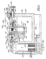
- FIGURE 4 is a side view, partially in section and illustrating a portion of the pump positioning system according to the preferred embodiment of the invention;
- FIGURE 5 is a perspective, exploded view of the swing arm assembly; and
- FIGURE 6 is an air flow and valve schematic for use in the illustrated preferred embodiment.
- In the various FIGURES, like reference numerals are used to indicate like components.
- Before proceeding to the description of the preferred embodiment of the present invention, several comments need to be made about the adaptability of the present invention. While the invention is illustrated in the context of casting straps for lead-acid storage batteries, the invention has much wider applicability to other processes where the casting of molten metal, or for that matter, the pouring of precise amounts of other liquids, is required. Relative dimensions could be widely varied, as could the number of pumps employed for any particular casting operation. The illustrated embodiment shows twelve casting pumps, six on each side, as would be employed in the construction of a standard twelve volt battery for an automobile, but a different number of pumps could be employed for other kinds of batteries. Moreover, the present specification does not attempt to describe the other plate assembly and battery construction techniques involved in manufacturing lead-acid storage batteries, because in and of themselves, such techniques are well-known and do not form part of the present invention. Suffice it to say that the principles of the present invention are readily adaptable to manual, automated or robotic battery manufacturing systems.
- Proceeding now to the description of the preferred embodiment, a
casting pump 10 is shown in FIGURES 1 and 2. Thepump 10 includes a body 12 (generally rectangular in horizontal or vertical cross section) and is preferably made from a steel which is suitable for immersion into liquid lead without degradation. Located at one end ofbody 12 is a generally cylindrical, verticallyoriented chamber 14.Chamber 14 is preferably located just inwardly of afirst end wall 16 ofpump 10.Chamber 14 is made by machining through the bottom 18 ofbody 12. Upon completion of the preparation ofchamber 14, a plate 20 is welded across the bottom as is shown byweld areas 22 in FIGURE 1. -
Chamber 14 extends a substantial distance upwardly intobody 12 and terminates at its upper end in a reduced diameter, threadedopening 24. Abolt 26 is threadingly received in opening 24 to sealinglyclose chamber 14. Careful machining of the top ofbody 12 and the underside ofbolt 26, together with an anti-seize compound, will help to ensure an air-tight seal at this location. Also shown in FIGURE 1 is a horizontal through-hole 28 extending through theend wall 16 ofbody 12 intochamber 14,hole 28 being adapted to receive afirst end 32 of an air supply pipe 34. Thesecond end 36 of pipe 34 is a coupling, the purpose of which will become apparent later in this description of the preferred embodiment. - The
end 30 ofbody 12 opposite fromend wall 16 is flared outwardly near its top into extensions 40 (see FIGURE 2) and three alignment projections 42-44 are carefully machined along the top edge ofend 30 for abutment against the edge of the mold block which will be described later. Thecentral extension 43 is actually the tip of apouring spout 45.Spout 45 opens to an inclined, generallycylindrical passageway 47 extending downwardly from the top ofbody 12 toward the bottom ofchamber 14. An intersecting, smaller,vertical hole 50 is machined throughbody 12 betweenchamber 14 and thetip 43 ofspout 45,hole 50 having a larger diameter above it point of intersection withpassageway 47 and a smaller diameter at thearea 52 betweenpassageway 47 and the bottom 18 ofbody 12. Ashort tube 54 is inserted into the top ofhole 50.Area 52 terminates at afill hole 56 at the bottom ofbody 12. - Other components of
pump 10 include aspout cover 60 which is provided betweentube 54 and the top edge of the pumpadjacent spout 45. Abolt 66 passes throughcover 60 and is threadingly received in ahole 68 in the top ofbody 12. Also shown in FIGURE 2 are a pair ofconductor rods 70 vertically received inbody 12, one on either side ofpassageway 47.Rods 70 are preferably made from a material having a high level of heat conductivity, such as copper. - The operation of
pump 10 will now be explained in general terms.Pump 10 will be placed into a container (described later) for the liquid to be poured, such as a bath ofmolten lead 72. The liquid will flow into thepump chamber 14,passageway 47 andtube 50 throughfill hole 56 and rise to the level of the liquid into which the pump is placed.Tube 50 is provided to insure thathole 56 remains open, and for that purpose, any type of elongate cleaning rod (not shown) may be inserted downwardly throughtube 54. Similarly, opening 24 may be accessed for cleaning of chamber 14 (should that become necessary) by removal ofbolt 26.Spout cover 60 is provided to keep contaminants away from molten lead in the spout area of the pump and to direct the molten lead into the mold cavities described hereafter. Together withrods 70, cover 60 assists in maintaining thepassageway 47 at a temperature above the melting point of the lead.Rods 70 carry the heat of the molten lead upwardly intobody 12 to a point well above the level of themolten liquid 72. -
Pump 10 allows the pouring of a specific quantity ofliquid 72 by injecting intochamber 14, throughhole 28, a specific amount of pressurized air. The amount is determined by control of incoming air pressure and time. It will be apparent that as air is introduced into theair space 75 above the liquid level inchamber 14, liquid will be forced upwardly inpassageway 47 in response thereto. Air injection is continued until the proper amount of lead has been dispensed fromspout 45, after which time thearea 75 is vented causing lead within the upper part ofpassageway 47 to fall. At the same time thechamber 14 is refilled by lead flowing inwardly throughfill hole 56 because of the hydrostatic pressure generated by thebath 72. The compressed air system will be described more fully below, but it will be mentioned here that a solenoid valve is provided forpump 10 and that 60-90 grams of lead is poured in the most preferred embodiment using 6,8 - 10,3 kPa (1.0-1.5 psi) air injected for approximately 2 second (1.5-2.5 seconds for a typical automobile battery application). - Proceeding now to a description of FIGURES 3 and 4, a typical battery
accumulator casting station 100 is shown in top view, with parts removed or not shown in detail for ease of explanation.Station 100 includes anelongate mold manifold 102 for supporting a plurality of casting mold blocks, one of which is shown at 103. This blocks in turn include mold cavities, two of which are shown at 104 and 105. As previously mentioned, the number, size and arrangement of the cavities will depend primarily on the type, size and design of a particular battery.Manifold 102 preferably includes cooling passages below the molds for fluid coolants as known in the art and/or cooling air passages. Furthermore, a knock-out system may be employed, as is illustrated in greater detail in FIGURE 4, to assist in removal of solidified parts from the cavities. - On either side of the manifold 102 is a
lead pot 106 made from steel and including inner andouter walls first end wall 109, a second end wall 110 and a bottom 112 (see FIGURE 4). Insulation is preferably used in the various walls and bottoms ofpots 106 for energy conservation, operator safety and the maintenance of an even and controlled lead temperature withinpots 106. Not shown in the FIGURES are the pair of cast immersion heaters (3kW in the most preferred embodiment) which are employed to maintain the lead temperature inpots 106 at about 850ºF. - Near
end walls 109, floats 115 are mounted on pivoting sensingarms 117 which in turn are coupled throughsensing elements 118 to a lead pump in another lead pot (not shown). The latter lead pot is for a larger supply of lead (held at about 482°C (900ºF)). A pump in the large pot maintains the level oflead 72 inpot 106 at or near the desired level. That level is not extremely critical. Deviations of about ±0,3 cm (±1/8") in level are acceptable for automotive battery manufacturing. - Also as noted in FIGURE 3, the pipes 34 extend outwardly from
outer walls 108 for coupling to the air supply system soon to be described, and mountingpins 130 are shown on the mold blocks 103 (see FIGURE 3A), a pair of which are provided for eachpump 10 to assist in proper alignment thereof with the mold cavity.Pins 130 are received inholes 132 on either side ofspout 45 inextensions 40. Together with projections 42-44, the pins insure a proper fit and alignment of thespout 45 with themold block 102. As can best be seen in FIGURES 3 and 4, asmall gap 133 on the order of 0,12-0,25 mm (.005 to .010 inch), is provided between theweir 135 of the mold casting (104 in this section). The gap assists in breaking the flow stream of molten lead when pouring is completed, allowing a reverse flow of lead intopump 10 and preventing the formation of undesirable stringers attached to the cast parts. - Pumps 110 are urged against the
mold block 103 by an adjustable, pivotableswing arm assembly 140 shown best in FIGURES 4 and 5 (only one side is shown).Assembly 140 includes a pair of generallyparallel plates 142 having a firsthooked end 144 and anouter end 146.Ends 144 are adapted to pivot about pins 143 located on either end of themanifold 102. Outer ends 146 include a downwardly extendingprojection 148. - Mounted between
projections 148 is asupport 150 extending generally above the upper edge of theouter wall 108. A horizontal hole 152 is provided insupport 150 for eachpump 10, and a vertical intersecting and threadedhole 154 is provided for each horizontal hole 152. An internally threadedcylinder 160 is loosely received through each of the holes 152 and is adjustably locked into position bybolts 165 inserted intoholes 154. A turninghandle 166 is provided to facilitate tightening and loosening ofbolts 165. - The
cylinders 160 each receive a threadedrod 170 theouter end 172 of which is secured to ahandle 174. The inner end 176 of therods 170 is adapted to abut theouter wall 16 ofpump 10 whencylinders 160 are properly positioned. - It will be appreciated then that by appropriate tightening and loosening of the two
handles mold block 102 and thatpins 130 will be placed into receivingholes 132. It will also be apparent that if all therods 170 are moved away from the pumps, and ifcylinders 160 are retracted, the entire swing arm assembly may be pivoted upwardly to provide access to thepumps 10 for maintenance. Theair gap 179 between the mold blocks 103 and thepumps 10, as maintained by projections 42-44, prevents undesirable heat transfer from thehot pump 10 to the cooler mold blocks 103. - Also shown in FIGURE 4 are
rods 180 and springs 182 which are part of the knock-out assembly which itself is known. The driver cylinder 184 of the preferred hydraulic variety of knock-out device is also shown in FIGURE 4. - Referring next to FIGURE 6, a schematic of the system used to supply and control the air flow to pipes 34 is shown. Air from a compressor (not shown) enters the system through a
pipe 198 at about 552 kPa (80 psi) and enters a filter/regulator 200 where it is purified or dried. Alow pressure regulator 204 is located downstream of filter/regulator 200 and aT 202, a branch 203 of which supplies other needs of the battery making equipment unrelated to the present invention. Theregulator 204 drops the pressure to about 8 kPa (1. 2 psi) in the preferred embodiment and it is maintained at that pressure in a large accumulator tank 206. Apipe 207 supplies air from tank 206 to twelve solenoid controlled valves 208 (one of which is shown in this FIGURE) which in turn selectively feeds air through a needle valve 210 to apipe 211 leading towardpump 10. Acoupling 212 on the end ofpipe 211 joins to thecoupling 36 of pipe 34. As mentioned previously, thevalve 208 allows air to flow into thepump chamber 14 for a preselected period of time, after which air is vented through valve 210. A solenoid 210 and the downstream components are provided for eachpump 10 in the preferred embodiment. - While an illustrated preferred embodiment of the invention has been described above, the invention could be variously embodied without departing from its intended scope. It is, therefore, to be limited solely by the scope of the claims which follow.
Claims (6)
- A system for pouring molten lead into a mold cavity (104, 105) comprising a receptacle lead pot (106), a bath of the molten lead, a pump housing (12) having a chamber (14) for containing the molten lead liquid, the housing (12) being at least partially immersed in the molten lead and having a refilling hole (56) communicating with the chamber (14), an inclined tubular passageway (47) in the housing communicating with the chamber (14) and terminating in a pouring spout (45), a conduit (34) for coupling the air source to the upper portion of the chamber (14), a valve (208) for admitting a predetermined amount of said low pressure air from the source through the conduit (34) and into the upper portion of the chamber to force a predetermined quantity of the liquid through the passageway (47) and out of the spout (45), one of said mold cavities (104, 105) being adjacent to but spaced apart from the spout (45), the system being characterized by a weir (135) adjacent the spout and arranged so that the molten lead flows over the weir when forced out of the spout, spacer means (42, 44) on the housing (12) for maintaining a predetermined spacing between the spout (45) and the weir (135) and means for urging the pump housing (12) against the receptacle lead pot (106) so that the spacing therebetween is maintained at the predetermined amount.
- The pouring system of claim 1 wherein the refilling hole is provided in the housing between the bath and the passageway (47).
- The pouring system of claim 1 wherein a clean-out hole is provided above the passageway (47) in the housing, said refilling and clean-out holes being axially aligned.
- The pouring system of claim 1 wherein thermal conductive metal rods (70) are imbedded in the housing (12) for heating the passageway (47).
- The pouring system of claim 1 and further comprising: a conduit for coupling an air source to the chamber (14), valve and timer means for admitting a predetermined amount of low pressure air from the source, through said conduit, and into the chamber (14) to force a predetermined quantity of the liquid through the passageway (47) and out of the spout (45), and thermal conductive metal rods (70) being embedded in the housing (12) in the vicinity of both the passageway (47) and the bath for heating the passageway (47).
- The pouring system of one of claims 1 to 5 wherein the rods (70) are copper rods.
Applications Claiming Priority (3)
| Application Number | Priority Date | Filing Date | Title |
|---|---|---|---|
| US07/591,611 US5146974A (en) | 1990-10-02 | 1990-10-02 | Lead pouring system |
| US591611 | 1990-10-02 | ||
| PCT/US1991/004393 WO1992005899A1 (en) | 1990-10-02 | 1991-06-21 | Lead pouring system |
Publications (2)
| Publication Number | Publication Date |
|---|---|
| EP0552166A1 EP0552166A1 (en) | 1993-07-28 |
| EP0552166B1 true EP0552166B1 (en) | 1995-08-23 |
Family
ID=24367153
Family Applications (1)
| Application Number | Title | Priority Date | Filing Date |
|---|---|---|---|
| EP91915063A Expired - Lifetime EP0552166B1 (en) | 1990-10-02 | 1991-06-21 | Lead pouring system |
Country Status (6)
| Country | Link |
|---|---|
| US (1) | US5146974A (en) |
| EP (1) | EP0552166B1 (en) |
| AT (1) | ATE126741T1 (en) |
| CA (1) | CA2093211A1 (en) |
| DE (1) | DE69112412D1 (en) |
| WO (1) | WO1992005899A1 (en) |
Families Citing this family (18)
| Publication number | Priority date | Publication date | Assignee | Title |
|---|---|---|---|---|
| GB9300356D0 (en) * | 1993-01-09 | 1993-03-03 | Tbs Eng Ltd | Apparatus for assembling battery plates |
| US5487496A (en) * | 1994-08-24 | 1996-01-30 | Gnb Battery Technologies, Inc. | Lead delivery system for casting straps in the manufacture and assembly of lead-acid batteries |
| US5900030A (en) * | 1996-10-15 | 1999-05-04 | Farmer Mold And Machine Works, Inc. | Apparatus for assembling a battery |
| DE29620957U1 (en) * | 1996-12-03 | 1997-02-27 | Hadi Offermann Maschbau | Pump for conveying molten lead |
| DE19710051B4 (en) * | 1997-03-12 | 2005-06-23 | Continental Teves Ag & Co. Ohg | Method for adjusting the total stroke of a solenoid valve and closing gauge |
| JP3507299B2 (en) * | 1997-09-05 | 2004-03-15 | 松下電器産業株式会社 | Method and apparatus for manufacturing lead storage battery |
| US6405786B1 (en) | 1999-05-27 | 2002-06-18 | Water Gremlin Company | Apparatus and method of forming parts |
| US6701998B2 (en) | 2002-03-29 | 2004-03-09 | Water Gremlin Company | Multiple casting apparatus and method |
| KR20050050120A (en) * | 2002-10-17 | 2005-05-27 | 말린크로트, 인코포레이티드 | Polymer pharmaceutical pig and associated method of use and associated method of production |
| US8701743B2 (en) | 2004-01-02 | 2014-04-22 | Water Gremlin Company | Battery parts and associated systems and methods |
| US7338539B2 (en) | 2004-01-02 | 2008-03-04 | Water Gremlin Company | Die cast battery terminal and a method of making |
| ES2746292T3 (en) | 2009-04-30 | 2020-03-05 | Water Gremlin Co | Battery parts that have sealing and retaining elements |
| US8061404B2 (en) * | 2009-12-18 | 2011-11-22 | MarcTech Innovative Design, Inc. | Mold for a battery cast on strap |
| US9748551B2 (en) | 2011-06-29 | 2017-08-29 | Water Gremlin Company | Battery parts having retaining and sealing features and associated methods of manufacture and use |
| CN102942388B (en) * | 2012-10-11 | 2014-03-19 | 安徽六国化工股份有限公司 | Anti-fouling V-shaped chute |
| US9954214B2 (en) | 2013-03-15 | 2018-04-24 | Water Gremlin Company | Systems and methods for manufacturing battery parts |
| GB2565588B (en) * | 2017-08-18 | 2022-03-02 | Tbs Eng Ltd | Lead delivery apparatus |
| EP3891821A4 (en) | 2018-12-07 | 2022-12-21 | Water Gremlin Company | Battery parts having solventless acid barriers and associated systems and methods |
Family Cites Families (23)
| Publication number | Priority date | Publication date | Assignee | Title |
|---|---|---|---|---|
| US2735148A (en) * | 1956-02-21 | Process for casting storage battery straps and terminals | ||
| DE460579C (en) * | 1928-06-01 | Robert Bosch Akt Ges | Injection molding process in which the metal flow is pressed from the injection vessel into the mold by means of a pressurized gas | |
| US703420A (en) * | 1899-08-01 | 1902-07-01 | Rudolph M Hunter | Process of making electric accumulator-plates. |
| US1843491A (en) * | 1926-04-20 | 1932-02-02 | Wood Newspaper Mach Corp | Pneumatic metal pump |
| US1747552A (en) * | 1927-08-17 | 1930-02-18 | Arthur D Lund | Grid-casting machine |
| US1736188A (en) * | 1928-06-27 | 1929-11-19 | Illinois Zinc Company | Apparatus for pouring molten metal |
| US2846740A (en) * | 1956-09-17 | 1958-08-12 | Lindberg Eng Co | Furnace ladling apparatus |
| US2816334A (en) * | 1956-09-24 | 1957-12-17 | Lindberg Eng Co | Automatic ladling control for metal melting furnace |
| US3229337A (en) * | 1962-09-24 | 1966-01-18 | Lindberg Engineering Co | Furnace ladling apparatus |
| US3510116A (en) * | 1967-08-30 | 1970-05-05 | Henry L Harvill | Metal dispensing furnace |
| US3499580A (en) * | 1968-07-02 | 1970-03-10 | Frank B Smith | Pressure pour apparatus and component thereof |
| US3675911A (en) * | 1968-11-11 | 1972-07-11 | Wiener Schwachstromwerke Gmbh | Arrangement for discharging predetermined amounts of molten metal from a vessel |
| US3708088A (en) * | 1970-11-20 | 1973-01-02 | Albany Int Corp | Apparatus for metering liquid flow discharge |
| SE364654B (en) * | 1971-11-18 | 1974-03-04 | Asea Ab | |
| US3876191A (en) * | 1973-03-15 | 1975-04-08 | Sola Basic Ind Inc | Furnace ladling apparatus and crucible |
| SU547289A1 (en) * | 1974-05-31 | 1977-02-25 | Предприятие П/Я Р-6930 | Device for dosed metal casting |
| US4158382A (en) * | 1976-12-23 | 1979-06-19 | General Battery Corporation | Apparatus for casting lead into plastic for side terminal batteries |
| US4284122A (en) * | 1976-12-23 | 1981-08-18 | General Battery Corporation | Method and apparatus for casting lead into plastic for side terminal batteries |
| DE2925297A1 (en) * | 1978-06-23 | 1980-02-07 | Stamp | METHOD AND DEVICE FOR ASSEMBLING ACCUMULATOR PLATES |
| GB2023471B (en) * | 1978-06-23 | 1982-06-09 | Stamp T | Casting battery strap onto battery plate lugs |
| JPS58212857A (en) * | 1982-06-05 | 1983-12-10 | Fuji Electric Co Ltd | Automatic charging furnace |
| JPS59215265A (en) * | 1983-05-24 | 1984-12-05 | Nachi Fujikoshi Corp | Device for ladling molten metal in specified amount |
| JPS62207558A (en) * | 1986-03-05 | 1987-09-11 | Toshiba Mach Co Ltd | Pouring device for die casting machine |
-
1990
- 1990-10-02 US US07/591,611 patent/US5146974A/en not_active Expired - Fee Related
-
1991
- 1991-06-21 CA CA002093211A patent/CA2093211A1/en not_active Abandoned
- 1991-06-21 WO PCT/US1991/004393 patent/WO1992005899A1/en active IP Right Grant
- 1991-06-21 EP EP91915063A patent/EP0552166B1/en not_active Expired - Lifetime
- 1991-06-21 AT AT91915063T patent/ATE126741T1/en not_active IP Right Cessation
- 1991-06-21 DE DE69112412T patent/DE69112412D1/en not_active Expired - Lifetime
Also Published As
| Publication number | Publication date |
|---|---|
| DE69112412D1 (en) | 1995-09-28 |
| US5146974A (en) | 1992-09-15 |
| EP0552166A1 (en) | 1993-07-28 |
| CA2093211A1 (en) | 1992-04-03 |
| ATE126741T1 (en) | 1995-09-15 |
| WO1992005899A1 (en) | 1992-04-16 |
Similar Documents
| Publication | Publication Date | Title |
|---|---|---|
| EP0552166B1 (en) | Lead pouring system | |
| US7497989B2 (en) | Molten metal pressure pour furnace | |
| US5913358A (en) | Casting apparatus and method | |
| US5657812A (en) | Metal-casting apparatus and method | |
| KR101234171B1 (en) | Alloy casting apparatus | |
| US3800986A (en) | Apparatus for discharging molten metals with pump emptying means | |
| SU502595A3 (en) | Low pressure casting device | |
| KR100696741B1 (en) | Method of and device for producing light metal castings, inparticluar parts of magnesium or magnesium alloys | |
| US6170559B1 (en) | Apparatus for casting a lead formation on battery plate lugs | |
| US4289193A (en) | Accumulator plate assembly methods | |
| RU2001114461A (en) | METHOD AND DEVICE FOR PRODUCTION OF PRODUCTS FROM LIGHT METALS, IN PARTICULAR, PARTS FROM MAGNESIUM AND MAGNESIUM ALLOYS | |
| CN111375745B (en) | Cast-weld device | |
| US3450190A (en) | Low pressure casting apparatus | |
| GB2023471A (en) | Casting battery strap onto battery plate lugs | |
| CN205057038U (en) | Package quick replacement mouth of a river device in middle of abnormal shape base continuous casting | |
| US6742568B2 (en) | Casting apparatus including a gas driven molten metal injector and method | |
| EP2723522A2 (en) | Molten metal holding and pouring box with dual pouring nozzles | |
| CN215544688U (en) | High-precision investment casting equipment for metal valve | |
| JPS63252667A (en) | Device for pouring molten metal | |
| KR102199565B1 (en) | Melt supply devicefor die casting | |
| JP2003501270A (en) | Method of heating bottom plate of row molding apparatus and row molding apparatus | |
| JPH0289557A (en) | Low pressure casting apparatus | |
| JPH04262847A (en) | Casting device | |
| US20010048186A1 (en) | Auger pump for handling magnesium and magnesium alloys | |
| JP2005095921A (en) | Casting method and casting apparatus |
Legal Events
| Date | Code | Title | Description |
|---|---|---|---|
| PUAI | Public reference made under article 153(3) epc to a published international application that has entered the european phase |
Free format text: ORIGINAL CODE: 0009012 |
|
| 17P | Request for examination filed |
Effective date: 19930402 |
|
| AK | Designated contracting states |
Kind code of ref document: A1 Designated state(s): AT BE CH DE DK ES FR GB GR IT LI LU NL SE |
|
| 17Q | First examination report despatched |
Effective date: 19931210 |
|
| GRAA | (expected) grant |
Free format text: ORIGINAL CODE: 0009210 |
|
| RAP3 | Party data changed (applicant data changed or rights of an application transferred) |
Owner name: GLOBE-UNION, INC. |
|
| AK | Designated contracting states |
Kind code of ref document: B1 Designated state(s): AT BE CH DE DK ES FR GB GR IT LI LU NL SE |
|
| PG25 | Lapsed in a contracting state [announced via postgrant information from national office to epo] |
Ref country code: IT Free format text: LAPSE BECAUSE OF FAILURE TO SUBMIT A TRANSLATION OF THE DESCRIPTION OR TO PAY THE FEE WITHIN THE PRESCRIBED TIME-LIMIT;WARNING: LAPSES OF ITALIAN PATENTS WITH EFFECTIVE DATE BEFORE 2007 MAY HAVE OCCURRED AT ANY TIME BEFORE 2007. THE CORRECT EFFECTIVE DATE MAY BE DIFFERENT FROM THE ONE RECORDED. Effective date: 19950823 Ref country code: CH Effective date: 19950823 Ref country code: LI Effective date: 19950823 Ref country code: FR Free format text: THE PATENT HAS BEEN ANNULLED BY A DECISION OF A NATIONAL AUTHORITY Effective date: 19950823 Ref country code: AT Effective date: 19950823 Ref country code: GR Free format text: LAPSE BECAUSE OF FAILURE TO SUBMIT A TRANSLATION OF THE DESCRIPTION OR TO PAY THE FEE WITHIN THE PRESCRIBED TIME-LIMIT Effective date: 19950823 Ref country code: DK Effective date: 19950823 Ref country code: ES Free format text: THE PATENT HAS BEEN ANNULLED BY A DECISION OF A NATIONAL AUTHORITY Effective date: 19950823 Ref country code: BE Effective date: 19950823 Ref country code: NL Free format text: LAPSE BECAUSE OF FAILURE TO SUBMIT A TRANSLATION OF THE DESCRIPTION OR TO PAY THE FEE WITHIN THE PRESCRIBED TIME-LIMIT Effective date: 19950823 |
|
| REF | Corresponds to: |
Ref document number: 126741 Country of ref document: AT Date of ref document: 19950915 Kind code of ref document: T |
|
| REF | Corresponds to: |
Ref document number: 69112412 Country of ref document: DE Date of ref document: 19950928 |
|
| REG | Reference to a national code |
Ref country code: CH Ref legal event code: PL |
|
| PG25 | Lapsed in a contracting state [announced via postgrant information from national office to epo] |
Ref country code: SE Effective date: 19951123 |
|
| PG25 | Lapsed in a contracting state [announced via postgrant information from national office to epo] |
Ref country code: DE Effective date: 19951124 |
|
| EN | Fr: translation not filed | ||
| NLV1 | Nl: lapsed or annulled due to failure to fulfill the requirements of art. 29p and 29m of the patents act | ||
| PLBE | No opposition filed within time limit |
Free format text: ORIGINAL CODE: 0009261 |
|
| STAA | Information on the status of an ep patent application or granted ep patent |
Free format text: STATUS: NO OPPOSITION FILED WITHIN TIME LIMIT |
|
| PG25 | Lapsed in a contracting state [announced via postgrant information from national office to epo] |
Ref country code: LU Free format text: LAPSE BECAUSE OF NON-PAYMENT OF DUE FEES Effective date: 19960630 |
|
| 26N | No opposition filed | ||
| PGFP | Annual fee paid to national office [announced via postgrant information from national office to epo] |
Ref country code: GB Payment date: 20010604 Year of fee payment: 11 |
|
| REG | Reference to a national code |
Ref country code: GB Ref legal event code: IF02 |
|
| PG25 | Lapsed in a contracting state [announced via postgrant information from national office to epo] |
Ref country code: GB Free format text: LAPSE BECAUSE OF NON-PAYMENT OF DUE FEES Effective date: 20020621 |
|
| GBPC | Gb: european patent ceased through non-payment of renewal fee |
Effective date: 20020621 |