EP0551976B1 - Apparatus for mounting a plate on a plate cylinder - Google Patents
Apparatus for mounting a plate on a plate cylinder Download PDFInfo
- Publication number
- EP0551976B1 EP0551976B1 EP93250013A EP93250013A EP0551976B1 EP 0551976 B1 EP0551976 B1 EP 0551976B1 EP 93250013 A EP93250013 A EP 93250013A EP 93250013 A EP93250013 A EP 93250013A EP 0551976 B1 EP0551976 B1 EP 0551976B1
- Authority
- EP
- European Patent Office
- Prior art keywords
- plate
- lockup device
- plate cylinder
- pair
- reference pins
- Prior art date
- Legal status (The legal status is an assumption and is not a legal conclusion. Google has not performed a legal analysis and makes no representation as to the accuracy of the status listed.)
- Expired - Lifetime
Links
Images

Classifications
-
- B—PERFORMING OPERATIONS; TRANSPORTING
- B41—PRINTING; LINING MACHINES; TYPEWRITERS; STAMPS
- B41F—PRINTING MACHINES OR PRESSES
- B41F27/00—Devices for attaching printing elements or formes to supports
- B41F27/005—Attaching and registering printing formes to supports
-
- B—PERFORMING OPERATIONS; TRANSPORTING
- B41—PRINTING; LINING MACHINES; TYPEWRITERS; STAMPS
- B41F—PRINTING MACHINES OR PRESSES
- B41F27/00—Devices for attaching printing elements or formes to supports
- B41F27/12—Devices for attaching printing elements or formes to supports for attaching flexible printing formes
- B41F27/1206—Feeding to or removing from the forme cylinder
-
- B—PERFORMING OPERATIONS; TRANSPORTING
- B41—PRINTING; LINING MACHINES; TYPEWRITERS; STAMPS
- B41F—PRINTING MACHINES OR PRESSES
- B41F33/00—Indicating, counting, warning, control or safety devices
- B41F33/02—Arrangements of indicating devices, e.g. counters
-
- B—PERFORMING OPERATIONS; TRANSPORTING
- B41—PRINTING; LINING MACHINES; TYPEWRITERS; STAMPS
- B41P—INDEXING SCHEME RELATING TO PRINTING, LINING MACHINES, TYPEWRITERS, AND TO STAMPS
- B41P2227/00—Mounting or handling printing plates; Forming printing surfaces in situ
- B41P2227/30—Detecting the correct position of printing plates on the cylinder
Definitions
- the present invention relates to a plate mounting apparatus in a printing press, which winds, on the circumferential surface of a plate cylinder, a plate having one end gripped by a leading-side plate lockup device provided in the gap formed in the outer circumferential surface of a plate cylinder, and causes a trailing-side plate lockup device in the gap in the outer circumferential surface of the plate cylinder to grip the other end of the plate, thereby mounting the plate on the plate cylinder.
- leading- and trailing-side plate lockup devices each including a plate lockup table and gripper plates pivotally supported by the plate lockup table are provided in a gap formed in the outer circumference surface of the plate cylinder.
- the leading end of a plate is gripped by the leading-side plate lockup device by opening and closing operations of the gripper plates, and wound on the circumferential surface of the plate cylinder by rotating the plate cylinder by almost one revolution, and thereafter the gripper plates are opened and closed so that the trailing-side plate lockup device grips the trailing end of the plate, so that the plate is mounted on the plate cylinder.
- ink and water are supplied to the surface of the mounted plate to form an image, and the image is transferred to paper being transported directly or through a blanket cylinder, thereby printing the image.
- the image is distortedly printed, degrading the quality of the printed matter.
- the different colors are misregistered which largely degrade the quality of the printed matter.
- U-shaped reference pin holes or notches are formed in the leading end of the plate, and the plate is made with reference to these reference pin holes.
- reference pins are provided on the plate gripper portion of the leading-side plate lockup device, and the plate is mounted while engaging the reference pin holes of the plate with these reference pins.
- Positioning means for other roller configurations are known, e.g. from GB-A-1 321 562 which ensures the correct positioning of a plate on a printing or similar roller by connecting dogs projecting out of the surface of the roller in an oscillatory circuit including a coil, whereby the circuit will oscillate when closed by means of an electrically conductive plate placed to abut against the dogs.
- the circuit When the circuit is closed, it energises a transmitter coil in separate detector circuit located on the roller frame which transfers an output to an indicator.
- EP-A-0 195 848 to provide holes in the end of the sheet which correspond to pins or dogs projecting from the surface of the cylinder and comprising an LED. When the holes in the plate are passed over the pins, a circuit is closed which illuminates the LED.
- an apparatus for mounting a plate on a plate cylinder comprising a plate lockup device associated with said plate cylinder and including gripper surfaces between which said plate mounted on said plate cylinder is securely held, detecting means, which conduct an electric current when an insertion end of said plate is inserted in the plate lockup device, indicator means for confirming and indicating whether the plate inserted in the plate lockup device is correctly positioned, wherein said plate lockup device is provided inside a gap formed in the circumferential surface of said plate cylinder such that it does not extend beyond the circumferential surface of said plate cylinder, said indicator means is provided on a stationary portion of said apparatus, and said detecting means comprise a pair of reference pins arranged on said plate lockup device inside said gap, such that they do not extend beyond the circumferential surface of said plate cylinder, said reference pins being adapted to engage with a pair of notches provided in said insertion end of said plate, whereby on insertion of said plate in said plate lockup device, each of said reference pins a
- Figs. 1 to 5 show a plate mounting apparatus for mounting a plate on a plate cylinder according to an embodiment of the present invention.
- a gap 2 is formed in the outer circumferential surface of a plate cylinder 1 over substantially the entire length thereof, and two open ends of the gap 2 are closed with disk-like bearers 3.
- a leading-side plate lockup device 4 and a trailing-side plate lockup device (not shown) having almost the same structure as that of the leading-side plate lockup device 4 are disposed in the gap 2 to extend parallel to each other over almost the entire length of the gap 2.
- the leading-side plate lockup device 4 has a plate lockup table 5 having a substantially rectangular section and extending in the axial direction of the gap 2.
- the plate lockup table 5 is positioned by a gauge plate 6 and fixed on the bottom surface of the gap 2 by bolts (not shown).
- a plurality of gripper plates 8 having substantially the same total length as that of the plate lockup table 5 and divided in the axial direction are swingably supported on the plate lockup table 5 by bolts (not shown).
- a cam shaft 11 having a plurality of cams each consisting of an arcuated portion 11a and a linear portion 11b is pivotally, axially supported, between a plate 10 pressed by a press plate 9 fixed on the end faces of the gripper plates 8 and a recess hole 5a of the plate lockup table 5, by the two bearers 3 and an intermediate bearing (not shown).
- a projecting portion 11c of the cam shaft 11 projecting from a bearer 3 and having an intermediate portion coupled through coupling has a hexagonal section, so that the projecting portion 11c can be engaged by a wrench to turn the cam shaft 11.
- the gripper plates 8 having gripper surfaces 8a are biased in the opening direction toward a gripper surface 5b of the plate lockup table 5 by the spring force of a spring member (not shown).
- the gripper plates 8 are swung by the cooperation of the pivoting operation of the cam shaft 11 and the spring force of the spring member, and the gripper surfaces 8a are opened away from the gripper surface 5b.
- U-shaped reference pin holes 13a and 13b are formed in the leading end of a plate 13 spaced apart from each other by a predetermined distance. Plate making is performed with reference to these reference pin holes 13a and 13b.
- two pairs of triangular notches 5c and 8b are formed in the plate lockup table 5 and the corresponding gripper plates 8 at positions close to the end portions thereof in the longitudinal direction, so that the notches 5c and 8b correspond to the reference pin holes 13a and 13b.
- a reference pin base 14 having a triangular shape when seen from above and an inverted L-shaped section, is housed in each pair of notches 5c and 8b, and is fixed on the bottom surface of the gap 2 by a bolt 15.
- Two reference pins 16 are inserted in pin holes 14a of the reference pin base 14 and fixed by nuts 18. The distance between the two reference pins 16 is set to be equal to the distance between the reference pin holes 13a and 13b formed in the plate 13.
- the reference pins 16 are engaged with the corresponding reference pin holes 13a and 13b of the plate 13 inserted between the gripper surfaces 5b and 8a.
- wires 21 and 22 connected to a power supply 20 are connected to the two reference pins 16 serving as the detecting portions, and the reference pins 16 are rendered conductive by an insertion end 13c of the conductive plate 13 inserted between the gripper surfaces 5b and 8a. More specifically, when the bottom portions of the reference pin holes 13a and 13b of the plate 13 contact the reference pins 16 to be electrically connected to them, the two reference pins 16 serving as the detecting portions are rendered conductive through the insertion end 13c of the plate 13.
- a lamp 23 serving as an indicator is provided to the stationary portion of the machine frame. The lamp 23 is turned on when the two reference pins 16 are rendered conductive through the insertion end 13c of the plate 13.
- the two reference pins 16 serving as the detecting portions of the plate cylinder 1 are rendered conductive by the insertion end 13c of the conductive plate 13.
- the two reference pins 16 serving as the detecting portions and the lamp 23 serving as the indicator form a loop to turn on the lamp 23, so that the operator can confirm that the plate 13 is reliably inserted.
- the cam shaft 11 is turned to cause the arcuated portions 11a of the cams to contact the plate 10.
- the gripper surfaces 5b and 8a are closed against the spring force of the spring member to grip one end of the plate 13.
- the plate cylinder 1 is rotated by almost one revolution to wind the plate 13 on the circumferential surface of the plate cylinder 1.
- the trailing-side plate lockup device is caused to grip the other end of the plate 13 in the same manner as described above, and the trailing-side plate lockup device is moved in the circumferential direction of the plate cylinder 1, so that the plate 13 is tightened and brought into tight contact with the circumferential surface of the plate cylinder 1, thus completing mounting of the plate 13.
- the lamp 23 indicates whether the plate 13 is reliably inserted between the gripper surfaces 5b and 8a of the leading-side plate lockup device 4. Therefore, the plate 13 can be reliably gripped.
- Figs. 6 to 12 show a plate mounting apparatus for mounting a plate on a plate cylinder according to another embodiment of the present invention.
- the same members as those of the apparatus shown in Figs. 1 to 5 are denoted by the same reference numerals, and a detailed description thereof will be omitted.
- a leading-side plate lockup device 4 and a trailing-side plate lockup device are disposed in a gap 2 of a plate cylinder 1 axially supported by frames 30. After one end of a plate 13 is gripped by the plate lockup table 5, the plate cylinder 1 is rotated to wind the plate 13 on its circumferential surface, and the other end of the plate 13 is gripped by the trailing-side plate lockup device. The plate 13 is mounted on the plate cylinder 1 in this manner.
- roller arms 32 are pivotally mounted on the right and left frames 30, and a plurality of guide rollers 34 are axially mounted on a roller shaft 33 having two ends rotatably axially supported by the free end portions of the roller arms 32.
- Air cylinders 35 are pivotally mounted on the right and left frames 30, and the operating ends of piston rods 36 of the air cylinders 35 are pivotally coupled to the roller shaft 33.
- a contact lever 37 is pivotally supported on one end of the roller shaft 33 by interposing a torsion coil spring 38 between the contact lever 37 and the roller arms 32.
- contact rollers 41 and 42 corresponding to contacts 39 and 40 provided to the plate cylinder 1 are pivotally mounted on the free end of the contact lever 37.
- the contacts 39 and 40 are located at predetermined positions on the end face of the plate cylinder 1 so that they contact the contact rollers 41 and 42 only when the plate cylinder 1 is kept stopped in the plate gripping operation.
- wires 43 and 44 connected to the contacts 39 and 40 are connected to the two reference pins 16 in the same manner as in Fig. 1.
- the contact rollers 41 and 42 are connected to the power supply 20 and the lamp 23 serving as the indicator through wires 45 and 46. When the contacts 39 and 40 are brought into tight contact with the contact rollers 41 and 42, they are connected to the power supply 20.
- the contact 39 and the contact roller 41, and the contact 40 and the contact roller 42 are rendered conductive.
- the two reference pins 16 have been rendered conductive by the plate 13, a loop is formed by the reference pins 16 serving as the detecting portions and the lamp 23 serving as the indicator, and the lamp 23 is turned on.
- the cam shaft 11 is turned to cause the arcuated portions 11a of the cams to contact the plate 10.
- the gripper surfaces 5b and 8a are closed against the spring force of the spring member to grip one end of the plate 13.
- the plate cylinder 1 is rotated by almost one revolution to wind the plate 13 on the circumferential surface of the plate cylinder 1.
- the trailing-side plate lockup device is caused to grip the other end of the plate 13 in the same manner as described above, and the trailing-side plate lockup device is moved in the circumferential direction of the plate cylinder 1, so that the plate 13 is tightened and brought into tight contact with the circumferential surface of the plate cylinder 1, thus completing mounting of the plate 13.
- the reference pins 16 are used also as the electrodes. However, electrodes may be provided independently of the reference pins. If, however, the reference pins are used also as the electrodes, the number of components is decreased.
- the plate mounting apparatus for mounting a plate on the plate cylinder, detecting portions, which are rendered conductive by the insertion end of a plate inserted between the gripper surfaces of the gripper plates and the gripper surface of the plate lockup table, and an indicator indicating that the detecting portions are rendered conductive are provided. Therefore, during the mounting operation of the plate on the plate cylinder, the indicator, e.g., a lamp or a buzzer, informs that the plate is completely inserted between the gripper surfaces of the gripper plates and the gripper surface of the plate lockup table. Insertion becomes reliable as compared to conventional insertion which is left to the discretion of the operator, and variations caused by differing degrees of skill of the operators are eliminated, thereby improving the quality of the printed matter.
- the indicator e.g., a lamp or a buzzer
- the detecting portions are provided to the plate cylinder which is a rotary member
- the indicator is provided to the stationary portion of the machine frame
- contacts are provided to render the detecting portions and the indicators conductive when the plate cylinder is stopped. Therefore, since the contacts for closing the electrical circuit are not closed during rotation of the plate cylinder, but are closed when the plate cylinder is kept stopped, the durability of the components forming the contact portions is improved. In addition, the problem of wiring between the plate cylinder as the rotary member and the indicator can be solved.
Landscapes
- Supply, Installation And Extraction Of Printed Sheets Or Plates (AREA)
- Unwinding Webs (AREA)
- Rolls And Other Rotary Bodies (AREA)
- Inking, Control Or Cleaning Of Printing Machines (AREA)
- Manufacture Or Reproduction Of Printing Formes (AREA)
Abstract
Description
- The present invention relates to a plate mounting apparatus in a printing press, which winds, on the circumferential surface of a plate cylinder, a plate having one end gripped by a leading-side plate lockup device provided in the gap formed in the outer circumferential surface of a plate cylinder, and causes a trailing-side plate lockup device in the gap in the outer circumferential surface of the plate cylinder to grip the other end of the plate, thereby mounting the plate on the plate cylinder.
- In a usual printing press, leading- and trailing-side plate lockup devices each including a plate lockup table and gripper plates pivotally supported by the plate lockup table are provided in a gap formed in the outer circumference surface of the plate cylinder. The leading end of a plate is gripped by the leading-side plate lockup device by opening and closing operations of the gripper plates, and wound on the circumferential surface of the plate cylinder by rotating the plate cylinder by almost one revolution, and thereafter the gripper plates are opened and closed so that the trailing-side plate lockup device grips the trailing end of the plate, so that the plate is mounted on the plate cylinder.
- In the printing operation, ink and water are supplied to the surface of the mounted plate to form an image, and the image is transferred to paper being transported directly or through a blanket cylinder, thereby printing the image. In this printing,operation, when the plate is distortedly mounted, the image is distortedly printed, degrading the quality of the printed matter. Especially, in multicolor printing, the different colors are misregistered which largely degrade the quality of the printed matter. For this reason, at the time of conventional plate making, U-shaped reference pin holes or notches are formed in the leading end of the plate, and the plate is made with reference to these reference pin holes. Simultaneously, reference pins are provided on the plate gripper portion of the leading-side plate lockup device, and the plate is mounted while engaging the reference pin holes of the plate with these reference pins.
- In such a conventional plate mounting apparatus, however, the gripper plates of the leading-side plate lockup device are opened, the end portion of the plate is inserted in the plate cylinder, the U-shaped bottom portion of the reference pin hole is brought into contact with the reference pin to position the plate, and the gripper plates are closed. That is, a skilled operator is required to confirm and determine whether the reference pin hole contacts the reference pin. However, since different operators have differing degrees of skill variations in positioning are inevitable, which leads to unsatisfactory results regarding positioning precision. When high precision positioning cannot be performed, a degradation in printing quality is caused.
- Positioning means for other roller configurations are known, e.g. from GB-A-1 321 562 which ensures the correct positioning of a plate on a printing or similar roller by connecting dogs projecting out of the surface of the roller in an oscillatory circuit including a coil, whereby the circuit will oscillate when closed by means of an electrically conductive plate placed to abut against the dogs. When the circuit is closed, it energises a transmitter coil in separate detector circuit located on the roller frame which transfers an output to an indicator. It is also known from EP-A-0 195 848 to provide holes in the end of the sheet which correspond to pins or dogs projecting from the surface of the cylinder and comprising an LED. When the holes in the plate are passed over the pins, a circuit is closed which illuminates the LED.
- It is an object of the present invention to provide a plate mounting apparatus capable of reliably mounting a plate on a plate cylinder.
- It is another object of the present invention to provide a plate mounting apparatus for mounting a plate on a plate cylinder to provide an improved printing quality.
- According to the present invention, there is provided an apparatus for mounting a plate on a plate cylinder comprising a plate lockup device associated with said plate cylinder and including gripper surfaces between which said plate mounted on said plate cylinder is securely held, detecting means, which conduct an electric current when an insertion end of said plate is inserted in the plate lockup device, indicator means for confirming and indicating whether the plate inserted in the plate lockup device is correctly positioned, wherein said plate lockup device is provided inside a gap formed in the circumferential surface of said plate cylinder such that it does not extend beyond the circumferential surface of said plate cylinder, said indicator means is provided on a stationary portion of said apparatus, and said detecting means comprise a pair of reference pins arranged on said plate lockup device inside said gap, such that they do not extend beyond the circumferential surface of said plate cylinder, said reference pins being adapted to engage with a pair of notches provided in said insertion end of said plate, whereby on insertion of said plate in said plate lockup device, each of said reference pins abuts the base of one notch, respectively, and forms an electrical contact therewith.
-
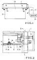
- Fig. 1 is a schematic view showing the arrangement of a plate mounting apparatus;
- Fig. 2 is a plan view of an end portion of a plate cylinder;
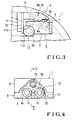
- Fig. 3 is a sectional view taken along the line III - III of Fig. 2;
- Fig. 4 is an enlarged plan view of a portion near a reference pin;
- Fig. 5 is a sectional view taken along the line V - V of Fig. 4;
- Fig. 6 is a schematic diagram showing the arrangement of the plate mounting apparatus;
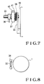
- Fig. 7 is a front view of the end portion of the plate cylinder;
- Fig. 8 is a side view of the end portion the plate cylinder;
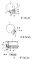
- Fig. 9 is a side view of the end portion of the plate cylinder showing a state wherein a plate is being inserted;
- Fig. 10 is a side view of the end portion of the plate cylinder showing a state wherein detecting portions are rendered conductive;
- Fig. 11 is a schematic front view of the end portion of the plate cylinder; and
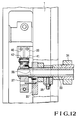
- Fig. 12 is a partially cutaway front view of the end portion of the plate cylinder.
- Figs. 1 to 5 show a plate mounting apparatus for mounting a plate on a plate cylinder according to an embodiment of the present invention. Referring to Figs. 1 to 5, a
gap 2 is formed in the outer circumferential surface of aplate cylinder 1 over substantially the entire length thereof, and two open ends of thegap 2 are closed with disk-like bearers 3. A leading-side plate lockup device 4 and a trailing-side plate lockup device (not shown) having almost the same structure as that of the leading-side plate lockup device 4 are disposed in thegap 2 to extend parallel to each other over almost the entire length of thegap 2. - Of the two plate lockup tables, the leading-side plate lockup device 4 has a plate lockup table 5 having a substantially rectangular section and extending in the axial direction of the
gap 2. The plate lockup table 5 is positioned by agauge plate 6 and fixed on the bottom surface of thegap 2 by bolts (not shown). A plurality ofgripper plates 8 having substantially the same total length as that of the plate lockup table 5 and divided in the axial direction are swingably supported on the plate lockup table 5 by bolts (not shown). Acam shaft 11 having a plurality of cams each consisting of an arcuatedportion 11a and alinear portion 11b is pivotally, axially supported, between aplate 10 pressed by apress plate 9 fixed on the end faces of thegripper plates 8 and arecess hole 5a of the plate lockup table 5, by the twobearers 3 and an intermediate bearing (not shown). - A projecting
portion 11c of thecam shaft 11 projecting from abearer 3 and having an intermediate portion coupled through coupling has a hexagonal section, so that the projectingportion 11c can be engaged by a wrench to turn thecam shaft 11. Thegripper plates 8 havinggripper surfaces 8a are biased in the opening direction toward agripper surface 5b of the plate lockup table 5 by the spring force of a spring member (not shown). Thegripper plates 8 are swung by the cooperation of the pivoting operation of thecam shaft 11 and the spring force of the spring member, and thegripper surfaces 8a are opened away from thegripper surface 5b. - The plate mounting apparatus will be described. As shown in Fig. 1, U-shaped
reference pin holes plate 13 spaced apart from each other by a predetermined distance. Plate making is performed with reference to thesereference pin holes triangular notches corresponding gripper plates 8 at positions close to the end portions thereof in the longitudinal direction, so that thenotches reference pin holes reference pin base 14, having a triangular shape when seen from above and an inverted L-shaped section, is housed in each pair ofnotches gap 2 by abolt 15. Tworeference pins 16 are inserted inpin holes 14a of thereference pin base 14 and fixed bynuts 18. The distance between the tworeference pins 16 is set to be equal to the distance between thereference pin holes plate 13. Thereference pins 16 are engaged with the correspondingreference pin holes plate 13 inserted between thegripper surfaces - In this plate mounting apparatus, as shown in Fig. 1,
wires power supply 20 are connected to the tworeference pins 16 serving as the detecting portions, and thereference pins 16 are rendered conductive by aninsertion end 13c of theconductive plate 13 inserted between thegripper surfaces reference pin holes plate 13 contact thereference pins 16 to be electrically connected to them, the tworeference pins 16 serving as the detecting portions are rendered conductive through theinsertion end 13c of theplate 13. Alamp 23 serving as an indicator is provided to the stationary portion of the machine frame. Thelamp 23 is turned on when the tworeference pins 16 are rendered conductive through theinsertion end 13c of theplate 13. - The operation of the plate mounting apparatus having the above-described arrangement will be described. To mount the
plate 13 on theplate cylinder 1, a wrench is engaged with the projectingportion 11c of thecam shaft 11 to turn thecam shaft 11, to cause thelinear portions 11b of the cams to contact theplate 10. Thus, thegripper plates 8 are swung by the spring force of the spring member to open thegripper surfaces plate 13 and inserts it between thegripper surfaces reference pin holes reference pins 16. When the bottom portions of thereference pin holes insertion end 13c of theplate 13 contact thereference pins 16, the tworeference pins 16 serving as the detecting portions of theplate cylinder 1 are rendered conductive by theinsertion end 13c of theconductive plate 13. As a result, the tworeference pins 16 serving as the detecting portions and thelamp 23 serving as the indicator form a loop to turn on thelamp 23, so that the operator can confirm that theplate 13 is reliably inserted. - Thereafter, the
cam shaft 11 is turned to cause thearcuated portions 11a of the cams to contact theplate 10. Then, thegripper surfaces plate 13. Theplate cylinder 1 is rotated by almost one revolution to wind theplate 13 on the circumferential surface of theplate cylinder 1. The trailing-side plate lockup device is caused to grip the other end of theplate 13 in the same manner as described above, and the trailing-side plate lockup device is moved in the circumferential direction of theplate cylinder 1, so that theplate 13 is tightened and brought into tight contact with the circumferential surface of theplate cylinder 1, thus completing mounting of theplate 13. During mounting of theplate 13 as described above, thelamp 23 indicates whether theplate 13 is reliably inserted between the gripper surfaces 5b and 8a of the leading-side plate lockup device 4. Therefore, theplate 13 can be reliably gripped. - Figs. 6 to 12 show a plate mounting apparatus for mounting a plate on a plate cylinder according to another embodiment of the present invention. Referring to Figs. 6 to 12, the same members as those of the apparatus shown in Figs. 1 to 5 are denoted by the same reference numerals, and a detailed description thereof will be omitted. A leading-side plate lockup device 4 and a trailing-side plate lockup device are disposed in a
gap 2 of aplate cylinder 1 axially supported byframes 30. After one end of aplate 13 is gripped by the plate lockup table 5, theplate cylinder 1 is rotated to wind theplate 13 on its circumferential surface, and the other end of theplate 13 is gripped by the trailing-side plate lockup device. Theplate 13 is mounted on theplate cylinder 1 in this manner. - As shown in Fig. 6,
roller arms 32 are pivotally mounted on the right and leftframes 30, and a plurality ofguide rollers 34 are axially mounted on aroller shaft 33 having two ends rotatably axially supported by the free end portions of theroller arms 32.Air cylinders 35 are pivotally mounted on the right and leftframes 30, and the operating ends ofpiston rods 36 of theair cylinders 35 are pivotally coupled to theroller shaft 33. As shown in Fig. 7, acontact lever 37 is pivotally supported on one end of theroller shaft 33 by interposing atorsion coil spring 38 between thecontact lever 37 and theroller arms 32. As shown in Fig. 12,contact rollers contacts plate cylinder 1 are pivotally mounted on the free end of thecontact lever 37. Thecontacts plate cylinder 1 so that they contact thecontact rollers plate cylinder 1 is kept stopped in the plate gripping operation. As shown in Fig. 6,wires contacts reference pins 16 in the same manner as in Fig. 1. As shown in Fig. 6, thecontact rollers power supply 20 and thelamp 23 serving as the indicator throughwires contacts contact rollers power supply 20. - The operation of the plate mounting apparatus having the above-described arrangement will be described. To mount the
plate 13 on theplate cylinder 1, a wrench is engaged with a projectingportion 11c of acam shaft 11 to turn thecam shaft 11, to cause thelinear portions 11b of the cams to contact theplate 10. Thus,gripper plates 8 are swung by the spring force of a spring member to open gripper surfaces 5b and 8a. The operator holds the leading end of theplate 13 and inserts it between the gripper surfaces 5b and 8a while engagingreference pin holes reference pin holes insertion end 13c of theplate 13 contact the reference pins 16, the tworeference pins 16 serving as the detecting portions of theplate cylinder 1 are rendered conductive by theplate 13, thereby forming a loop. - When the
plate 13 is to be inserted between the gripper surfaces 5b and 8a, as shown in Fig. 9, thepiston rods 36 of theair cylinders 35 are moved forward to swing theroller arms 32, and the plurality ofguide rollers 34 are moved to the guide position of theplate cylinder 1. Hence, one end of theplate 13 is guided to a portion between the gripper surfaces 5b and 8a by theguide rollers 34, and is reliably inserted between them. Upon movement of theguide rollers 34, thecontact lever 37 coaxial with theroller arms 32 is swung, and as shown in Fig. 10, thecontact rollers contacts torsion coil spring 38. Then, thecontact 39 and thecontact roller 41, and thecontact 40 and thecontact roller 42 are rendered conductive. In addition, since the tworeference pins 16 have been rendered conductive by theplate 13, a loop is formed by the reference pins 16 serving as the detecting portions and thelamp 23 serving as the indicator, and thelamp 23 is turned on. - When the
lamp 23 is turned on and it is confirmed that theplate 13 is reliably inserted, thecam shaft 11 is turned to cause thearcuated portions 11a of the cams to contact theplate 10. As a result, the gripper surfaces 5b and 8a are closed against the spring force of the spring member to grip one end of theplate 13. Theplate cylinder 1 is rotated by almost one revolution to wind theplate 13 on the circumferential surface of theplate cylinder 1. The trailing-side plate lockup device is caused to grip the other end of theplate 13 in the same manner as described above, and the trailing-side plate lockup device is moved in the circumferential direction of theplate cylinder 1, so that theplate 13 is tightened and brought into tight contact with the circumferential surface of theplate cylinder 1, thus completing mounting of theplate 13. - In the embodiments described above, the reference pins 16 are used also as the electrodes. However, electrodes may be provided independently of the reference pins. If, however, the reference pins are used also as the electrodes, the number of components is decreased.
- As is apparent from the above description,
in the plate mounting apparatus according to the present invention for mounting a plate on the plate cylinder, detecting portions, which are rendered conductive by the insertion end of a plate inserted between the gripper surfaces of the gripper plates and the gripper surface of the plate lockup table, and an indicator indicating that the detecting portions are rendered conductive are provided. Therefore, during the mounting operation of the plate on the plate cylinder, the indicator, e.g., a lamp or a buzzer, informs that the plate is completely inserted between the gripper surfaces of the gripper plates and the gripper surface of the plate lockup table. Insertion becomes reliable as compared to conventional insertion which is left to the discretion of the operator, and variations caused by differing degrees of skill of the operators are eliminated, thereby improving the quality of the printed matter. - Furthermore, the detecting portions are provided to the plate cylinder which is a rotary member, the indicator is provided to the stationary portion of the machine frame, and contacts are provided to render the detecting portions and the indicators conductive when the plate cylinder is stopped. Therefore, since the contacts for closing the electrical circuit are not closed during rotation of the plate cylinder, but are closed when the plate cylinder is kept stopped, the durability of the components forming the contact portions is improved. In addition, the problem of wiring between the plate cylinder as the rotary member and the indicator can be solved.
Claims (6)
- An apparatus for mounting a plate on a plate cylinder comprising:
a plate lockup device (4) associated with said plate cylinder (1) and including gripper surfaces (5b, 8a) between which said plate (13) mounted on said plate cylinder (1) is securely held,
detecting means, which conduct an electric current when an insertion end (13c) of said plate (13) is inserted in the plate lockup device (4), and
indicator means (23) for confirming and indicating whether the plate (13) inserted in the plate lockup device (4) is correctly positioned,
said apparatus being characterised in that
said plate lockup device (4) is provided inside a gap (2) formed in the curcumferential surface of said plate cylinder (1) such that it does not extend beyond the circumferential surface of said plate cylinder (1)
said indicator means (23) is provided on a stationary portion of said apparatus, and
said detecting means comprise a pair of reference pins (16) arranged on said plate lockup device (4) inside said gap (2), such that they do not extend beyond the circumferential surface of said plate cylinder (1), said reference pins (16) being adapted to engage with a pair of notches (13a, 13b) provided in said insertion end (13c) of said plate (13), whereby on insertion of said plate in said plate lockup device, each of said reference pins (16) abuts the base of one notch (13a, 13b) respectively and forms an electrical contact therewith. - An apparatus according to claim 1, wherein said pair of reference pins are respectively fixed on reference pin bases (14) provided in the gap of said plate cylinder.
- An apparatus according to claim 2, wherein connecting means (39 to 42) are provided for connecting said pair of reference pins (16) and said indicating means (23) when said plate cylinder (1) stops at a predetermined position to allow insertion of said plate insertion end (13c) in said plate lockup device (4).
- An apparatus according to claim 1, wherein said pair of reference pins are electrically connected to one another by the insertion end of the plate (13c) when the notches (13a, 13b) of said plate (13) are engaged with said reference pins (16).
- An apparatus according to claim 3, wherein said connecting means comprises a pair of contacts (39, 40) formed on said plate cylinder and a pair of contact rollers (41, 42) provided on said stationary portion of said machine frame, and said pair of contact rollers are brought into tight contact with said pair of contacts when the plate is gripped.
- An apparatus according to claim 5, further comprising a guide member (34) for guiding the plate to said gripper surface of said plate lockup device when the plate is gripped, and wherein said pair of contact rollers are brought into tight contact with said contacts in synchronism with an operation of said guide member.
Applications Claiming Priority (3)
| Application Number | Priority Date | Filing Date | Title |
|---|---|---|---|
| JP2599392 | 1992-01-17 | ||
| JP02599392A JP3194199B2 (en) | 1992-01-17 | 1992-01-17 | Plate mounting device on plate cylinder |
| JP25993/92 | 1992-01-17 |
Publications (3)
| Publication Number | Publication Date |
|---|---|
| EP0551976A1 EP0551976A1 (en) | 1993-07-21 |
| EP0551976B1 true EP0551976B1 (en) | 1996-07-03 |
| EP0551976B2 EP0551976B2 (en) | 2002-10-16 |
Family
ID=12181244
Family Applications (1)
| Application Number | Title | Priority Date | Filing Date |
|---|---|---|---|
| EP93250013A Expired - Lifetime EP0551976B2 (en) | 1992-01-17 | 1993-01-14 | Apparatus for mounting a plate on a plate cylinder |
Country Status (5)
| Country | Link |
|---|---|
| US (1) | US5383402A (en) |
| EP (1) | EP0551976B2 (en) |
| JP (1) | JP3194199B2 (en) |
| AT (1) | ATE139936T1 (en) |
| DE (1) | DE69303380T3 (en) |
Cited By (10)
| Publication number | Priority date | Publication date | Assignee | Title |
|---|---|---|---|---|
| US5461980A (en) * | 1992-07-31 | 1995-10-31 | Komori Corporation | Plate mounting apparatus for printing press |
| US5634406A (en) * | 1994-11-05 | 1997-06-03 | Man Roland Druckmaschinen Ag | Method for automatically feeding a printing plate to a plate cylinder in a printing machine |
| US5806431A (en) * | 1996-05-24 | 1998-09-15 | Koenig & Bauer-Albert Aktiengesellschaft | Method and apparatus for axially positioning a printing plate |
| US5992325A (en) * | 1998-01-30 | 1999-11-30 | Heidelberger Druckmaschinen Aktiengesellschaft | Method and device for automatically detecting at least one printing plate edge |
| US6135027A (en) * | 1998-01-30 | 2000-10-24 | Heidelberger Druckmaschinen Aktiengesellschaft | Device for in-register positioning of a printing plate |
| EP1046502A1 (en) * | 1999-04-22 | 2000-10-25 | MAN Roland Druckmaschinen AG | Device for controlling the registered positioning of printing plates |
| EP1046501A1 (en) * | 1999-04-22 | 2000-10-25 | MAN Roland Druckmaschinen AG | Device for controlling the position of printing plates on plate cylinders of printing machines |
| US6463854B1 (en) | 1999-03-10 | 2002-10-15 | Heidelberger Druckmaschinen Ag | Device for detecting a printing plate position |
| US6691616B2 (en) | 1999-05-07 | 2004-02-17 | Heidelberger Druckmaschinen Ag | Device for detecting the position of a printing plate on a cylinder of a rotary printing machine |
| US6845713B1 (en) | 1998-12-23 | 2005-01-25 | Heidelberger Druckmaschinen Ag | Device for registering a printing plate position |
Families Citing this family (23)
| Publication number | Priority date | Publication date | Assignee | Title |
|---|---|---|---|---|
| JP3379974B2 (en) | 1992-02-10 | 2003-02-24 | 株式会社小森コーポレーション | Plate mounting status confirmation device |
| DE4223908C2 (en) * | 1992-06-30 | 1995-09-28 | Lehner Gmbh | Clamping device for clamping and adjusting a printing plate on a plate cylinder |
| DE4226780C2 (en) * | 1992-08-13 | 1994-12-01 | Roland Man Druckmasch | Device for checking the correct registration of a printing plate on the plate cylinder of printing machines, in particular sheetfed offset printing machines |
| DE4394496D2 (en) * | 1992-09-18 | 1995-09-21 | Koenig & Bauer Ag | Process for feeding printing plates |
| DE4338664C2 (en) * | 1993-11-12 | 1995-09-14 | Roland Man Druckmasch | Method and device for controlling an automated printing plate changing process in printing machines |
| DE4340052C2 (en) * | 1993-11-24 | 1996-06-13 | Roland Man Druckmasch | Device for checking the registration of a printing plate on a plate cylinder of a printing press |
| DE9418049U1 (en) * | 1994-11-11 | 1994-12-22 | MAN Roland Druckmaschinen AG, 63075 Offenbach | Device for registering printing plates |
| ATE176627T1 (en) * | 1995-04-26 | 1999-02-15 | Heidelberger Druckmasch Ag | METHOD AND DEVICE FOR CLAMPING A PRINTING PLATE ON A CYLINDER |
| US6113346A (en) | 1996-07-31 | 2000-09-05 | Agfa Corporation | Method for loading and unloading a supply of plates in an automated plate handler |
| DE29701585U1 (en) * | 1997-01-31 | 1997-03-13 | MAN Roland Druckmaschinen AG, 63075 Offenbach | printing plate |
| DE19803723A1 (en) * | 1998-01-30 | 1999-08-05 | Heidelberger Druckmasch Ag | Method and device for pre-positioning a printing plate in register |
| DE29808098U1 (en) * | 1998-05-06 | 1998-07-16 | MAN Roland Druckmaschinen AG, 63075 Offenbach | Register control facility |
| DE19839149C1 (en) * | 1998-08-28 | 2000-01-20 | Roland Man Druckmasch | Monitoring in-register plate positioning for printing machine cylinder |
| DE29815444U1 (en) * | 1998-08-28 | 1998-11-26 | MAN Roland Druckmaschinen AG, 63075 Offenbach | Power supply for a printing press cylinder |
| DE29815443U1 (en) | 1998-08-28 | 1998-11-26 | MAN Roland Druckmaschinen AG, 63075 Offenbach | Register control facility |
| US6125757A (en) * | 1998-10-19 | 2000-10-03 | Heidelberger Druckmaschinen Ag | Method and apparatus for performing a flying printing plate change |
| DE19921272A1 (en) * | 1999-05-07 | 2000-11-09 | Heidelberger Druckmasch Ag | Piezoceramic clamping monitoring device for detecting a printing plate position |
| ES2259588T3 (en) * | 1999-09-14 | 2006-10-16 | Komori Corporation | IRON INTRODUCTION APPARATUS ON A ROTATE PRINT TO PRINT. |
| US6460457B1 (en) * | 1999-11-22 | 2002-10-08 | Heidelberger Druckmaschinen Ag | Method and device for automatically providing a printing plate to a plate cylinder |
| US6318262B1 (en) * | 2000-02-25 | 2001-11-20 | Agfa Corporation | External drum imaging system |
| US6510793B1 (en) * | 2001-06-28 | 2003-01-28 | Eastman Kodak Company | Imaging apparatus and printing plate mounting surface for use in an imaging apparatus having printing plate registration detection |
| US6739250B2 (en) * | 2002-03-20 | 2004-05-25 | Fuji Photo Film Co., Ltd. | Device for controlling rotation of rotating drum |
| DE102006048676B4 (en) * | 2006-10-14 | 2011-07-07 | KOENIG & BAUER Aktiengesellschaft, 97080 | Device for detecting the presence of an elevator on a cylinder |
Family Cites Families (7)
| Publication number | Priority date | Publication date | Assignee | Title |
|---|---|---|---|---|
| GB1321562A (en) * | 1971-06-15 | 1973-06-27 | Teledictor Ltd | Conductive sheet detection apparatus |
| DE3000576A1 (en) * | 1980-01-09 | 1981-07-16 | Grapho-Metronic Meß- und Regeltechnik GmbH & Co, KG, 8000 München | Position register system for printing machine - uses plate position which is repeatedly fixed by probe to trigger electric contact |
| DE3138865C2 (en) * | 1981-09-30 | 1983-12-29 | Grapho Metronic Meß- und Regeltechnik GmbH & Co KG, 8000 München | Device for checking the exact register clamping of printing plates on the plate cylinder of an offset printing machine |
| DE3325583C2 (en) * | 1983-07-15 | 1991-12-12 | Heinz 5653 Leichlingen Metje | Stop system for printing plates, in particular for printing plate punches |
| DE3438931A1 (en) * | 1984-10-24 | 1986-04-24 | Heidelberger Druckmaschinen Ag, 6900 Heidelberg | DEVICE FOR ADJUSTING A FLEXIBLE PRINT PLATE ON THE PLATE CYLINDER OF ROTARY PRINTING MACHINES |
| IT1183507B (en) * | 1985-03-28 | 1987-10-22 | Arnoldo Mandadori Editore Offi | DEVICE FOR REGISTRATION OF THE PRINTING PLATES ON THE CYLINDERS OF FLAT OFFSET PRINTING MACHINES |
| DE3638428C1 (en) * | 1986-11-11 | 1988-06-01 | 2 B Praez Stechnik Gmbh Fuer D | Processing device with in-register positioning for offset printing formes |
-
1992
- 1992-01-17 JP JP02599392A patent/JP3194199B2/en not_active Expired - Fee Related
-
1993
- 1993-01-14 DE DE69303380T patent/DE69303380T3/en not_active Expired - Fee Related
- 1993-01-14 EP EP93250013A patent/EP0551976B2/en not_active Expired - Lifetime
- 1993-01-14 AT AT93250013T patent/ATE139936T1/en not_active IP Right Cessation
-
1994
- 1994-03-10 US US08/209,607 patent/US5383402A/en not_active Expired - Lifetime
Cited By (11)
| Publication number | Priority date | Publication date | Assignee | Title |
|---|---|---|---|---|
| US5461980A (en) * | 1992-07-31 | 1995-10-31 | Komori Corporation | Plate mounting apparatus for printing press |
| US5634406A (en) * | 1994-11-05 | 1997-06-03 | Man Roland Druckmaschinen Ag | Method for automatically feeding a printing plate to a plate cylinder in a printing machine |
| US5806431A (en) * | 1996-05-24 | 1998-09-15 | Koenig & Bauer-Albert Aktiengesellschaft | Method and apparatus for axially positioning a printing plate |
| US5992325A (en) * | 1998-01-30 | 1999-11-30 | Heidelberger Druckmaschinen Aktiengesellschaft | Method and device for automatically detecting at least one printing plate edge |
| US6135027A (en) * | 1998-01-30 | 2000-10-24 | Heidelberger Druckmaschinen Aktiengesellschaft | Device for in-register positioning of a printing plate |
| DE19854845B4 (en) * | 1998-01-30 | 2011-02-24 | Heidelberger Druckmaschinen Ag | Method and device for automatic detection of at least one printing plate edge |
| US6845713B1 (en) | 1998-12-23 | 2005-01-25 | Heidelberger Druckmaschinen Ag | Device for registering a printing plate position |
| US6463854B1 (en) | 1999-03-10 | 2002-10-15 | Heidelberger Druckmaschinen Ag | Device for detecting a printing plate position |
| EP1046502A1 (en) * | 1999-04-22 | 2000-10-25 | MAN Roland Druckmaschinen AG | Device for controlling the registered positioning of printing plates |
| EP1046501A1 (en) * | 1999-04-22 | 2000-10-25 | MAN Roland Druckmaschinen AG | Device for controlling the position of printing plates on plate cylinders of printing machines |
| US6691616B2 (en) | 1999-05-07 | 2004-02-17 | Heidelberger Druckmaschinen Ag | Device for detecting the position of a printing plate on a cylinder of a rotary printing machine |
Also Published As
| Publication number | Publication date |
|---|---|
| ATE139936T1 (en) | 1996-07-15 |
| EP0551976A1 (en) | 1993-07-21 |
| DE69303380T2 (en) | 1997-02-06 |
| DE69303380D1 (en) | 1996-08-08 |
| US5383402A (en) | 1995-01-24 |
| DE69303380T3 (en) | 2003-06-12 |
| JP3194199B2 (en) | 2001-07-30 |
| EP0551976B2 (en) | 2002-10-16 |
| JPH05193114A (en) | 1993-08-03 |
Similar Documents
| Publication | Publication Date | Title |
|---|---|---|
| EP0551976B1 (en) | Apparatus for mounting a plate on a plate cylinder | |
| EP0581212B2 (en) | Plate mounting apparatus for printing press | |
| US4147105A (en) | Protective device for a perfector printing press | |
| EP0503750A1 (en) | Apparatus for mounting plate on plate cylinder | |
| JP3790563B2 (en) | Device for guiding the printing plate | |
| US5746132A (en) | Variable repeat plate and blanket cylinder mechanism | |
| JPH082638B2 (en) | Image adjustment device for sheet-fed printing press | |
| JP2571056Y2 (en) | Plate changing device for printing press | |
| JP2929521B2 (en) | Device for supplying plate to plate cylinder of printing machine | |
| JP3375601B2 (en) | Typesetting replacement method and device | |
| US4480545A (en) | Offset press having two printing units with alternate path delivery cylinders | |
| CN1003118B (en) | Clamping strips on coiling cylinders of rotary presses | |
| US4833988A (en) | Inking device for printing apparatus | |
| JP2579079B2 (en) | Device for supporting the impression cylinder of a rotary printing press | |
| JP3933801B2 (en) | Plate changer | |
| EP0595762B1 (en) | Plate clamping device for offset press | |
| JPH0349880Y2 (en) | ||
| JPH06270393A (en) | Automatically mounting method for press plate | |
| EP0595761B1 (en) | Plate clamping device for offset press | |
| JPH11334044A (en) | Registering controller | |
| JP3220909B2 (en) | Plate press device of rotary printing press. | |
| EP0595760B1 (en) | Plate clamping device for offset press | |
| JPH01148553A (en) | Click seat height adjustment device of sheet feed printer | |
| JP3347466B2 (en) | Printing press safety devices | |
| JPH0526374U (en) | Plate guide device for printing machine |
Legal Events
| Date | Code | Title | Description |
|---|---|---|---|
| PUAI | Public reference made under article 153(3) epc to a published international application that has entered the european phase |
Free format text: ORIGINAL CODE: 0009012 |
|
| 17P | Request for examination filed |
Effective date: 19930205 |
|
| AK | Designated contracting states |
Kind code of ref document: A1 Designated state(s): AT CH DE FR GB IT LI NL SE |
|
| 17Q | First examination report despatched |
Effective date: 19940128 |
|
| GRAH | Despatch of communication of intention to grant a patent |
Free format text: ORIGINAL CODE: EPIDOS IGRA |
|
| GRAA | (expected) grant |
Free format text: ORIGINAL CODE: 0009210 |
|
| AK | Designated contracting states |
Kind code of ref document: B1 Designated state(s): AT CH DE FR GB IT LI NL SE |
|
| REF | Corresponds to: |
Ref document number: 139936 Country of ref document: AT Date of ref document: 19960715 Kind code of ref document: T |
|
| REF | Corresponds to: |
Ref document number: 69303380 Country of ref document: DE Date of ref document: 19960808 |
|
| ET | Fr: translation filed | ||
| ITF | It: translation for a ep patent filed | ||
| REG | Reference to a national code |
Ref country code: CH Ref legal event code: NV Representative=s name: PATENTANWALTSBUREAU BOSSHARD UND LUCHS |
|
| PLBI | Opposition filed |
Free format text: ORIGINAL CODE: 0009260 |
|
| PLBI | Opposition filed |
Free format text: ORIGINAL CODE: 0009260 |
|
| 26 | Opposition filed |
Opponent name: MAN ROLAND DRUCKMASCHINEN AG Effective date: 19970306 |
|
| PLBF | Reply of patent proprietor to notice(s) of opposition |
Free format text: ORIGINAL CODE: EPIDOS OBSO |
|
| 26 | Opposition filed |
Opponent name: HEIDELBERGER DRUCKMASCHINEN AG Effective date: 19970329 Opponent name: MAN ROLAND DRUCKMASCHINEN AG Effective date: 19970306 |
|
| NLR1 | Nl: opposition has been filed with the epo |
Opponent name: MAN ROLAND DRUCKMASCHINEN AG |
|
| NLR1 | Nl: opposition has been filed with the epo |
Opponent name: HEIDELBERGER DRUCKMASCHINEN AG Opponent name: MAN ROLAND DRUCKMASCHINEN AG |
|
| PLBF | Reply of patent proprietor to notice(s) of opposition |
Free format text: ORIGINAL CODE: EPIDOS OBSO |
|
| PLAW | Interlocutory decision in opposition |
Free format text: ORIGINAL CODE: EPIDOS IDOP |
|
| APAC | Appeal dossier modified |
Free format text: ORIGINAL CODE: EPIDOS NOAPO |
|
| APAE | Appeal reference modified |
Free format text: ORIGINAL CODE: EPIDOS REFNO |
|
| APAC | Appeal dossier modified |
Free format text: ORIGINAL CODE: EPIDOS NOAPO |
|
| APAC | Appeal dossier modified |
Free format text: ORIGINAL CODE: EPIDOS NOAPO |
|
| REG | Reference to a national code |
Ref country code: GB Ref legal event code: IF02 |
|
| PLAW | Interlocutory decision in opposition |
Free format text: ORIGINAL CODE: EPIDOS IDOP |
|
| PUAH | Patent maintained in amended form |
Free format text: ORIGINAL CODE: 0009272 |
|
| 27A | Patent maintained in amended form |
Effective date: 20021016 |
|
| AK | Designated contracting states |
Kind code of ref document: B2 Designated state(s): AT CH DE FR GB IT LI NL SE |
|
| REG | Reference to a national code |
Ref country code: CH Ref legal event code: AEN Free format text: AUFRECHTERHALTUNG DES PATENTES IN GEAENDERTER FORM |
|
| NLR2 | Nl: decision of opposition | ||
| NLR3 | Nl: receipt of modified translations in the netherlands language after an opposition procedure | ||
| ET3 | Fr: translation filed ** decision concerning opposition | ||
| APAH | Appeal reference modified |
Free format text: ORIGINAL CODE: EPIDOSCREFNO |
|
| PGFP | Annual fee paid to national office [announced via postgrant information from national office to epo] |
Ref country code: AT Payment date: 20090113 Year of fee payment: 17 |
|
| PGFP | Annual fee paid to national office [announced via postgrant information from national office to epo] |
Ref country code: NL Payment date: 20090115 Year of fee payment: 17 Ref country code: DE Payment date: 20090108 Year of fee payment: 17 |
|
| PGFP | Annual fee paid to national office [announced via postgrant information from national office to epo] |
Ref country code: GB Payment date: 20090114 Year of fee payment: 17 Ref country code: CH Payment date: 20090114 Year of fee payment: 17 |
|
| PGFP | Annual fee paid to national office [announced via postgrant information from national office to epo] |
Ref country code: SE Payment date: 20090108 Year of fee payment: 17 Ref country code: IT Payment date: 20090127 Year of fee payment: 17 |
|
| PGFP | Annual fee paid to national office [announced via postgrant information from national office to epo] |
Ref country code: FR Payment date: 20090113 Year of fee payment: 17 |
|
| REG | Reference to a national code |
Ref country code: NL Ref legal event code: V1 Effective date: 20100801 |
|
| REG | Reference to a national code |
Ref country code: CH Ref legal event code: PL |
|
| GBPC | Gb: european patent ceased through non-payment of renewal fee |
Effective date: 20100114 |
|
| EUG | Se: european patent has lapsed | ||
| REG | Reference to a national code |
Ref country code: FR Ref legal event code: ST Effective date: 20100930 |
|
| PG25 | Lapsed in a contracting state [announced via postgrant information from national office to epo] |
Ref country code: NL Free format text: LAPSE BECAUSE OF NON-PAYMENT OF DUE FEES Effective date: 20100801 Ref country code: LI Free format text: LAPSE BECAUSE OF NON-PAYMENT OF DUE FEES Effective date: 20100131 Ref country code: FR Free format text: LAPSE BECAUSE OF NON-PAYMENT OF DUE FEES Effective date: 20100201 Ref country code: CH Free format text: LAPSE BECAUSE OF NON-PAYMENT OF DUE FEES Effective date: 20100131 |
|
| PG25 | Lapsed in a contracting state [announced via postgrant information from national office to epo] |
Ref country code: DE Free format text: LAPSE BECAUSE OF NON-PAYMENT OF DUE FEES Effective date: 20100803 Ref country code: AT Free format text: LAPSE BECAUSE OF NON-PAYMENT OF DUE FEES Effective date: 20100114 |
|
| PG25 | Lapsed in a contracting state [announced via postgrant information from national office to epo] |
Ref country code: GB Free format text: LAPSE BECAUSE OF NON-PAYMENT OF DUE FEES Effective date: 20100114 |
|
| PG25 | Lapsed in a contracting state [announced via postgrant information from national office to epo] |
Ref country code: IT Free format text: LAPSE BECAUSE OF NON-PAYMENT OF DUE FEES Effective date: 20100114 |
|
| PG25 | Lapsed in a contracting state [announced via postgrant information from national office to epo] |
Ref country code: SE Free format text: LAPSE BECAUSE OF NON-PAYMENT OF DUE FEES Effective date: 20100115 |