EP0551537A1 - Méthode et dispositif pour mesurer vitesse de rotation par un interféromètre à fibre optique du type sagnac - Google Patents
Méthode et dispositif pour mesurer vitesse de rotation par un interféromètre à fibre optique du type sagnac Download PDFInfo
- Publication number
- EP0551537A1 EP0551537A1 EP92100460A EP92100460A EP0551537A1 EP 0551537 A1 EP0551537 A1 EP 0551537A1 EP 92100460 A EP92100460 A EP 92100460A EP 92100460 A EP92100460 A EP 92100460A EP 0551537 A1 EP0551537 A1 EP 0551537A1
- Authority
- EP
- European Patent Office
- Prior art keywords
- signal
- adder
- add1
- random number
- number generator
- Prior art date
- Legal status (The legal status is an assumption and is not a legal conclusion. Google has not performed a legal analysis and makes no representation as to the accuracy of the status listed.)
- Granted
Links
- 238000000034 method Methods 0.000 title claims abstract description 23
- 239000000835 fiber Substances 0.000 title claims description 15
- 238000011156 evaluation Methods 0.000 claims description 28
- 238000012360 testing method Methods 0.000 claims description 20
- 102100034004 Gamma-adducin Human genes 0.000 claims description 12
- 101000799011 Homo sapiens Gamma-adducin Proteins 0.000 claims description 12
- 102100024348 Beta-adducin Human genes 0.000 claims description 9
- 101000689619 Homo sapiens Beta-adducin Proteins 0.000 claims description 9
- 230000003111 delayed effect Effects 0.000 claims description 9
- 230000010363 phase shift Effects 0.000 claims description 9
- 230000003321 amplification Effects 0.000 claims description 8
- 230000010354 integration Effects 0.000 claims description 8
- 238000003199 nucleic acid amplification method Methods 0.000 claims description 8
- 238000012935 Averaging Methods 0.000 claims description 7
- 102100023882 Endoribonuclease ZC3H12A Human genes 0.000 claims description 7
- 101710112715 Endoribonuclease ZC3H12A Proteins 0.000 claims description 7
- QGVYYLZOAMMKAH-UHFFFAOYSA-N pegnivacogin Chemical compound COCCOC(=O)NCCCCC(NC(=O)OCCOC)C(=O)NCCCCCCOP(=O)(O)O QGVYYLZOAMMKAH-UHFFFAOYSA-N 0.000 claims description 7
- 230000008878 coupling Effects 0.000 claims description 6
- 238000010168 coupling process Methods 0.000 claims description 6
- 238000005859 coupling reaction Methods 0.000 claims description 6
- 108700012361 REG2 Proteins 0.000 claims description 5
- 101150108637 REG2 gene Proteins 0.000 claims description 5
- 101100120298 Rattus norvegicus Flot1 gene Proteins 0.000 claims description 5
- 101100412403 Rattus norvegicus Reg3b gene Proteins 0.000 claims description 5
- 230000035945 sensitivity Effects 0.000 claims description 4
- 101100301524 Drosophila melanogaster Reg-5 gene Proteins 0.000 claims description 3
- 230000000712 assembly Effects 0.000 claims description 2
- 238000000429 assembly Methods 0.000 claims description 2
- 239000002131 composite material Substances 0.000 claims description 2
- 238000001914 filtration Methods 0.000 claims description 2
- 230000001360 synchronised effect Effects 0.000 claims 1
- 230000006870 function Effects 0.000 description 9
- 102100034033 Alpha-adducin Human genes 0.000 description 7
- 101000799076 Homo sapiens Alpha-adducin Proteins 0.000 description 7
- 101000629598 Rattus norvegicus Sterol regulatory element-binding protein 1 Proteins 0.000 description 7
- 238000012545 processing Methods 0.000 description 6
- 230000001419 dependent effect Effects 0.000 description 4
- 230000000875 corresponding effect Effects 0.000 description 3
- 101001096074 Homo sapiens Regenerating islet-derived protein 4 Proteins 0.000 description 2
- 102100037889 Regenerating islet-derived protein 4 Human genes 0.000 description 2
- 101100322582 Streptomyces coelicolor (strain ATCC BAA-471 / A3(2) / M145) add1 gene Proteins 0.000 description 2
- 238000009825 accumulation Methods 0.000 description 2
- 230000002596 correlated effect Effects 0.000 description 2
- 238000010586 diagram Methods 0.000 description 2
- 230000000694 effects Effects 0.000 description 2
- 238000004519 manufacturing process Methods 0.000 description 2
- 238000012546 transfer Methods 0.000 description 2
- 108091058543 REG3 Proteins 0.000 description 1
- 102100027336 Regenerating islet-derived protein 3-alpha Human genes 0.000 description 1
- 238000004458 analytical method Methods 0.000 description 1
- 230000005540 biological transmission Effects 0.000 description 1
- 230000000295 complement effect Effects 0.000 description 1
- 238000013461 design Methods 0.000 description 1
- 238000011161 development Methods 0.000 description 1
- 230000018109 developmental process Effects 0.000 description 1
- 230000002452 interceptive effect Effects 0.000 description 1
- 238000005259 measurement Methods 0.000 description 1
- 230000003287 optical effect Effects 0.000 description 1
- 230000000087 stabilizing effect Effects 0.000 description 1
- 238000012916 structural analysis Methods 0.000 description 1
Images

Classifications
-
- G—PHYSICS
- G01—MEASURING; TESTING
- G01C—MEASURING DISTANCES, LEVELS OR BEARINGS; SURVEYING; NAVIGATION; GYROSCOPIC INSTRUMENTS; PHOTOGRAMMETRY OR VIDEOGRAMMETRY
- G01C19/00—Gyroscopes; Turn-sensitive devices using vibrating masses; Turn-sensitive devices without moving masses; Measuring angular rate using gyroscopic effects
- G01C19/58—Turn-sensitive devices without moving masses
- G01C19/64—Gyrometers using the Sagnac effect, i.e. rotation-induced shifts between counter-rotating electromagnetic beams
- G01C19/72—Gyrometers using the Sagnac effect, i.e. rotation-induced shifts between counter-rotating electromagnetic beams with counter-rotating light beams in a passive ring, e.g. fibre laser gyrometers
- G01C19/726—Phase nulling gyrometers, i.e. compensating the Sagnac phase shift in a closed loop system
Definitions
- the starting point of the invention is the fiber-optic Sagnac interferometer described in EP-A1-0 441 998 (Ref. [5]; see attached list of literature) which is suitable for inertial rotation rate measurement, also referred to as fiber-optic gyroscope for short, in which bias errors caused by electromagnetic overcoupling and insensitivity areas based thereon are eliminated by a modulation method controlled by a random number generator, which guarantees freedom from correlation of a demodulator reference signal.
- the in Ref. [5] the solution described requires great circuit complexity of the modules for generating the modulation and demodulation signal and for obtaining a control signal for the scale factor control loop.
- the invention has for its object to provide a method and an arrangement or device for measuring rotation rate by means of a fiber optic gyroscope, with which the signals for modulation and demodulation and the signals for stabilizing the scale factor in a much simpler manner can be generated.
- completely digital signal processing is to be made possible with an arrangement to be implemented as an integrated circuit (ASIC), which is free from production-related deviations in the effective loop amplification.
- ASIC integrated circuit
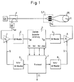
- the light waves pass through a coupler K and are then split into two partial beams in a beam splitter S.
- u ⁇ is the control voltage of the phase modulator P and c1 the electro-optical coupling factor.
- the constant c0 depends on the average light output at the receiver, i.e. on the photodetector D, on its sensitivity and the gain of subsequent stages.
- the beam splitter S and the phase modulator P are identified as one component by a dashed border. This component can be designed as an integrated PYP chip.
- the lower part of the arrangement of FIG. 1 has the purpose of bringing the Sagnac interferometer into a state by feeding suitable signals into the phase modulator P, which state permits an evaluation of the detector signal u det for the purpose of determining the rotation rate ⁇ (t).
- the signal u det generated by the photodetector Det is fed to an amplifier stage 1 with the adjustable gain a0.
- the signal is brought to a defined level a0 ⁇ u det and then digitized by an AD converter.
- the signal x AD obtained is fed to a digital evaluation circuit 3, which is explained in detail below.
- This digital evaluation circuit 3 generates an output signal y DA , which is converted into an analog voltage by a DA converter 4 and, after multiplication with an adjustable gain factor a 1, is supplied to the phase modulator P.
- the DA converter 4 is expediently provided as a multiplying DA converter 4, 5, a voltage supplied by an auxiliary DA converter 8 being used at its reference voltage input 9 to influence the gain.
- the digital evaluation circuit 3, the AD converter 2 and the multiplying DA converter 4, 5 work with the cycle time T0. This forms a closed signal path, the function of which is described in detail below.
- the digital evaluation circuit 3 delivers the output variables y ⁇ for the rotation rate, y a0 for the gain factor a0 of the input branch which can be set via a reference input 10 at the amplifier stage 1 and y a1 for the gain factor a1 of the multiplying DA converter 4, 5 at specific, selectable times in the output branch. All these variables are averaged values which are made available to a processor 7 for further processing.
- An input "clear" of the evaluation circuit 3 is operated by the processor 7 or a timer after each reading of the averaged output values and serves to reset internal averaging devices, which are also explained in more detail below.
- the processor 7 calculates from the averaged quantities y ⁇ , y a0 and y a1 after any further filtering, the measured variable, ie the rotation rate ⁇ (t) and the digital signals necessary for setting the amplification factors a0 and a1, via the auxiliary DAC 6 or 8 influence the assigned amplifier stages 1 or 5.
- the input signal x AD supplied by the AD converter 2 is given as an internal signal s 1 to an input of a first adder ADD 1.
- the size n can be preset within predetermined limits and, as will be shown, is used to adapt the runtime to the external signal path, which in addition to the interferometer also includes the modules 1, 2, 4 and 5 of FIG. 1.
- the other input of the first adder ADD1 is connected to a first register pair RP1, in which two predetermined values + d and -d, also referred to as test variables, are stored.
- this test variable d is fed as an additional signal into the main control loop (see chapter 4.2.1) with the aim of "measuring” its loop gain and this with an auxiliary control loop (reference path, see chapter 4.2.3) the controllable amplifier stage 1 influences, to a defined To regulate the setpoint.
- the test signal ⁇ d superimposed on the useful signal should be chosen to be sufficiently small to avoid overloading the external gyro path. If the gain is set correctly, as will be shown, this test signal is exactly compensated for, so that the measuring accuracy of the interferometer remains unaffected.
- a select input s is present, which is acted upon by a control signal D 1.
- the numbers (1) ... (8) of the quantities represented by equations are also entered in FIG. 2 in order to facilitate understanding of the function of the evaluation circuit of FIG. 2.
- the signal d'1 arises, analogously to d'2, by an n-stage delay with the aid of a second delay V2 from a signal d1.
- the signal d 1 is generated by a second random number generator D independent of the first random number generator M.
- the sum s2 generated by ADD1 is fed to the inputs of two first and second averaging devices MW1 and MW2 or digital filters described below with a fifth adder ADD5 or a sixth adder ADD6 and to a first input of a second adder ADD2.
- the remaining bits are fed to a first input of a phase integrator PI consisting of a fourth adder ADD4 and a second register REG2.
- the sum output s5 from ADD4 also contains only all bits with values less than 2 ⁇ . It is delayed by REG2 by one clock and fed back to the other input of the fourth adder ADD4.
- the resulting carry bit C is given as an input signal d3 to a third, also n-stage retarder V3.
- the signals s2 and s3 are, as mentioned above, connected to the inputs of three digital filters or averaging MW1, MW2 or MW3. These are externally resettable accumulators, each made up of an adder, the output of which is fed back via an assigned register to an adder input, so that the signal to be averaged is summed up over a predetermined period of m clock cycles.
- the averaged yaw rate y ⁇ is created by accumulating s3 with ADD7 via a fifth register REG5:
- the manipulated variable y a0 for the amplification factor a0 arises in the first mean value generator MW1 through an accumulation of s2 carried out with ADD5 via a third register REG3, an additional weighting of s2 depending on d'1 being carried out with +1 or -1:
- the setting variable y a1 for the gain factor a1 arises from weighted accumulation of s2 dependent on d'3 in the second mean value generator MW2 with ADD6 and a fourth register REG4.
- the sign weighting d'3 corresponds to the signal d3 delayed by the third delay V3 by n clocks, which is formed from the carry bit C with the valency 2 ⁇ of the fourth adder ADD4 of the phase integrator PI:
- n-1 dead times should also be taken into account.
- x AD (i + n) cos ( ⁇ ⁇ S '+ y AD (i + 1) - y THERE (i)) (11)
- s5 (i) - s5 (i - 1) mod2 ⁇ [s4 (i)] - 2 ⁇ d3 (i) (24)
- the right side of this equation can be interpreted as a two's complement number with the sign bit d3.
- So d3 is the sign of the scale factor deviation (a1c1 - 1) modulating signal [s5 (i) - s5 (i - 1)] .
- the error modulated in this way appears after n clocks with the signal s2 at the output of the first adder ADD1 and is demodulated with the sign d'3 (i), also delayed by n clocks, in order to derive the controlled variable for a1.
- the second averager MW2 made up of ADD6 and REG4.
- the additional demodulation takes place via the ⁇ control input of the adder ADD6.
- the averaged signal y a0 is a measure of the deviation of the product a0c0 from 1 and can be used to set the control variable a0 to the setpoint of the amplifier stage 5.
- Insensitive areas of the rotation rate measuring arrangement are caused by overcoupling the signal y DA to the input x AD , if at the same time the signal components present in y DA , originating from the first random number generator M, are correlated with the demodulator reference d'2.
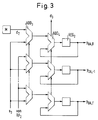
- An analysis at full adder level shows the structure illustrated in Fig. 3 for the adders ADD3, ADD4 and the second register REG2.
- the signal d2 supplied by the first random number generator M affects only the most significant bit MSB of the DA converter 4.
- y DA, 0 The total output of a full adder, viewed as a logical function, provides the EXOR combination of the two input summands and a possible input carry. Taking into account the commutativity of the EXOR operation, it can be seen from the structure diagram of FIG.
- the interferometer, the amplifiers 1, 5, the transducers 2, 4 and the evaluation circuit 3 are provided multiple times.
- the evaluation circuit 3 for one axis may react to rotation rates in another axis.
- This problem has been eliminated with the invention by using the statistically independent demodulator references.
- the decoupling is still effective even if all three detector signals are added together to form a single common signal for all three channels. This results in the possibility of building multi-axis systems with a single analog input path, consisting of the detector D, the input amplifier 1 and the AD converter 2.
Landscapes
- Engineering & Computer Science (AREA)
- Physics & Mathematics (AREA)
- Power Engineering (AREA)
- Optics & Photonics (AREA)
- Electromagnetism (AREA)
- General Physics & Mathematics (AREA)
- Radar, Positioning & Navigation (AREA)
- Remote Sensing (AREA)
- Gyroscopes (AREA)
Priority Applications (5)
| Application Number | Priority Date | Filing Date | Title |
|---|---|---|---|
| EP92100460A EP0551537B1 (fr) | 1992-01-13 | 1992-01-13 | Méthode et dispositif pour mesurer vitesse de rotation par un interféromètre à fibre optique du type sagnac |
| DE59201728T DE59201728D1 (de) | 1992-01-13 | 1992-01-13 | Verfahren und Einrichtung zur Drehratenmessung mittels eines faseroptischen Sagnac-Interferometers. |
| CA002072208A CA2072208C (fr) | 1992-01-13 | 1992-06-24 | Methode et appareil pour stabilisaer la boude de commande et gain dans l'interferometre sagnac a fibres optiques |
| US07/973,761 US5351123A (en) | 1992-01-13 | 1992-11-09 | Method and apparatus for stabilizing control loop scale factor and gain in a fiber optic Sagnac interferometer |
| JP5000090A JP2510460B2 (ja) | 1992-01-13 | 1993-01-04 | 回転速度測定のための方法および装置 |
Applications Claiming Priority (1)
| Application Number | Priority Date | Filing Date | Title |
|---|---|---|---|
| EP92100460A EP0551537B1 (fr) | 1992-01-13 | 1992-01-13 | Méthode et dispositif pour mesurer vitesse de rotation par un interféromètre à fibre optique du type sagnac |
Publications (2)
| Publication Number | Publication Date |
|---|---|
| EP0551537A1 true EP0551537A1 (fr) | 1993-07-21 |
| EP0551537B1 EP0551537B1 (fr) | 1995-03-22 |
Family
ID=8209238
Family Applications (1)
| Application Number | Title | Priority Date | Filing Date |
|---|---|---|---|
| EP92100460A Expired - Lifetime EP0551537B1 (fr) | 1992-01-13 | 1992-01-13 | Méthode et dispositif pour mesurer vitesse de rotation par un interféromètre à fibre optique du type sagnac |
Country Status (5)
| Country | Link |
|---|---|
| US (1) | US5351123A (fr) |
| EP (1) | EP0551537B1 (fr) |
| JP (1) | JP2510460B2 (fr) |
| CA (1) | CA2072208C (fr) |
| DE (1) | DE59201728D1 (fr) |
Cited By (5)
| Publication number | Priority date | Publication date | Assignee | Title |
|---|---|---|---|---|
| DE19629260C1 (de) * | 1996-07-19 | 1998-02-26 | Litef Gmbh | Elektrooptischer Phasenmodulator mit richtungsunabhängiger Impulsantwort, Anordnung von elektrooptischen Phasenmodulatoren und Verwendung eines elektrooptischen Phasenmodulators |
| EP1038155B1 (fr) * | 1997-12-12 | 2003-07-23 | LITEF GmbH | Dispositif de mesure de longueur d'onde a interferometre de mach-zehnder pilote sans moyenne |
| WO2005024344A1 (fr) * | 2003-08-29 | 2005-03-17 | Litef Gmbh | Procede pour detecter/compenser des erreurs systematiques/de cheminement aleatoire induites par la source lumineuse dans des interferometres de sagnac a fibres optiques |
| US7190463B2 (en) | 2001-06-22 | 2007-03-13 | Litef Gmbh | Method for preventing bias-errors as a result of synchronous interference in fiber-optic gyroscopes |
| CN109931922A (zh) * | 2017-12-15 | 2019-06-25 | 湖南中部芯谷科技有限公司 | 一种光纤陀螺启动快速自检测方法 |
Families Citing this family (31)
| Publication number | Priority date | Publication date | Assignee | Title |
|---|---|---|---|---|
| US5576534A (en) * | 1994-07-29 | 1996-11-19 | Litton Systems, Inc. | Error reduction by quasi non-multiplexed signal processing in a multiplexed fiber optic rotation sensor loop |
| US5504580A (en) * | 1994-11-30 | 1996-04-02 | Alliedsignal Inc. | Tuned integrated optic modulator on a fiber optic gyroscope |
| US5684589A (en) * | 1995-08-28 | 1997-11-04 | Litton Systems, Inc. | Loop controller for fiber optic gyro with distributed data processing |
| US6563589B1 (en) | 1996-04-19 | 2003-05-13 | Kvh Industries, Inc. | Reduced minimum configuration fiber optic current sensor |
| US5903350A (en) * | 1997-02-03 | 1999-05-11 | Optiphase, Inc. | Demodulator and method useful for multiplexed optical sensors |
| DE19748909C1 (de) * | 1997-11-05 | 1999-04-22 | Litef Gmbh | Verfahren zur Vermeidung von Nullpunktfehlern in einem faseroptischen Sagnac-Interferometer |
| US5946097A (en) * | 1997-12-31 | 1999-08-31 | Honeywell Inc. | Vibration rectification error reducer for fiber optic gyroscope |
| US5953123A (en) * | 1997-12-31 | 1999-09-14 | Aai Corporation | Fixed interval background auto-alignment for closed loop interferometric fiber optic gyroscopes |
| US6539134B1 (en) | 1999-02-11 | 2003-03-25 | Kvh Industries, Inc. | Polarization transformer |
| US6891622B2 (en) | 1999-02-11 | 2005-05-10 | Kvh Industries, Inc. | Current sensor |
| KR100449802B1 (ko) * | 1999-08-10 | 2004-09-22 | 한국전자통신연구원 | 초고주파 회로 및 초고주파 시스템의 안정도 판정방법 |
| US6961369B1 (en) | 1999-11-09 | 2005-11-01 | Aware, Inc. | System and method for scrambling the phase of the carriers in a multicarrier communications system |
| US6370289B1 (en) | 2000-01-12 | 2002-04-09 | Kvh Industries, Inc. | Apparatus and method for electronic RIN reduction in fiber-optic sensors |
| ATE265049T1 (de) | 2000-02-28 | 2004-05-15 | Kvh Ind Inc | Faraday-effekt-stromsonde mit verbesserter schwingungsreaktion |
| US6594020B2 (en) | 2000-07-13 | 2003-07-15 | Kvh Industries, Inc | Method for controlling fiber optic sensor scale factor using amplitude modulation |
| AU2002217751A1 (en) | 2000-08-02 | 2002-03-26 | Kvh Industries, Inc. | Decreasing the effects of linear birefringence in a fiber-optic sensor by use of berry's topological phase |
| US7120323B2 (en) * | 2000-08-02 | 2006-10-10 | Kvh Industries, Inc. | Reduction of linear birefringence in circular-cored single-mode fiber |
| US6836334B2 (en) * | 2001-10-31 | 2004-12-28 | Kvh Industries, Inc. | Angle random walk (ARW) noise reduction in fiber optic sensors using an optical amplifier |
| US6763153B2 (en) * | 2002-04-17 | 2004-07-13 | Kvh Industries, Inc. | Apparatus and method for electronic RIN reduction in fiber-optic sensors utilizing filter with group delay |
| US7453576B2 (en) * | 2005-11-29 | 2008-11-18 | Honeywell International Inc. | Method and system for calibrating a fiber optic gyroscope |
| US7583384B2 (en) * | 2006-07-27 | 2009-09-01 | Honeywell International, Inc. | High resolution IOC drive and method for driving fiber optic gyroscopes |
| JP5262165B2 (ja) * | 2008-02-18 | 2013-08-14 | パナソニック株式会社 | デジタルagc回路およびそれを用いた角速度センサ |
| JP5262164B2 (ja) * | 2008-02-18 | 2013-08-14 | パナソニック株式会社 | デジタルagc回路およびそれを用いた角速度センサ |
| US7847715B2 (en) * | 2008-08-04 | 2010-12-07 | Honeywell International Inc. | Segmented optics circuit drive for closed loop fiber optic sensors |
| US8542364B1 (en) * | 2009-12-17 | 2013-09-24 | Honeywell International Inc. | System to reduce gyroscopic errors with limited power supply quality in a fiber optic gyroscope |
| DE102011018468B3 (de) * | 2011-04-21 | 2012-03-29 | Northrop Grumman Litef Gmbh | Unterdrückung von Quantisierungsrauschen beim faseroptischen Sagnac-Interferometer |
| RU2512599C1 (ru) * | 2012-10-24 | 2014-04-10 | Федеральное государственное унитарное предприятие "Центр эксплуатации объектов наземной космической инфраструктуры" (ФГУП "ЦЭНКИ") | Способ повышения точности волоконно-оптического гироскопа с закрытым контуром |
| DE102015004039A1 (de) * | 2015-03-27 | 2016-09-29 | Northrop Grumman Litef Gmbh | Mittelwertfrei gesteuerter Phasenmodulator für faseroptische Kreisel und faseroptischer Kreisel |
| CN112097924B (zh) * | 2020-08-26 | 2021-09-28 | 安徽大学 | 基于相位生成载波技术的相位灵敏度标定方法 |
| DE102020213286A1 (de) * | 2020-10-21 | 2022-04-21 | Robert Bosch Gesellschaft mit beschränkter Haftung | Verfahren zur Bestimmung einer Phasenlage eines Drehratensignals oder eines Quadratursignals, Verfahren zur Anpassung einer Demodulationsphase und Drehratensensor |
| CN112595307B (zh) * | 2020-10-30 | 2022-09-16 | 西安航天精密机电研究所 | 一种干涉式光纤陀螺光路误差计算方法 |
Citations (2)
| Publication number | Priority date | Publication date | Assignee | Title |
|---|---|---|---|---|
| EP0436052A1 (fr) * | 1990-01-03 | 1991-07-10 | LITEF GmbH | nnterféromètre de Sagnac à fibre optique avec rappel numérique de déphasage pour la mesure de la vitesse de rotation |
| EP0441998B1 (fr) * | 1990-02-12 | 1993-06-02 | LITEF GmbH | Interféromètre de Sagnac à fibre optique avec annulation numérique de déphasage pour la mesure de la vitesse de rotation |
-
1992
- 1992-01-13 DE DE59201728T patent/DE59201728D1/de not_active Expired - Lifetime
- 1992-01-13 EP EP92100460A patent/EP0551537B1/fr not_active Expired - Lifetime
- 1992-06-24 CA CA002072208A patent/CA2072208C/fr not_active Expired - Lifetime
- 1992-11-09 US US07/973,761 patent/US5351123A/en not_active Expired - Lifetime
-
1993
- 1993-01-04 JP JP5000090A patent/JP2510460B2/ja not_active Expired - Fee Related
Patent Citations (2)
| Publication number | Priority date | Publication date | Assignee | Title |
|---|---|---|---|---|
| EP0436052A1 (fr) * | 1990-01-03 | 1991-07-10 | LITEF GmbH | nnterféromètre de Sagnac à fibre optique avec rappel numérique de déphasage pour la mesure de la vitesse de rotation |
| EP0441998B1 (fr) * | 1990-02-12 | 1993-06-02 | LITEF GmbH | Interféromètre de Sagnac à fibre optique avec annulation numérique de déphasage pour la mesure de la vitesse de rotation |
Cited By (7)
| Publication number | Priority date | Publication date | Assignee | Title |
|---|---|---|---|---|
| DE19629260C1 (de) * | 1996-07-19 | 1998-02-26 | Litef Gmbh | Elektrooptischer Phasenmodulator mit richtungsunabhängiger Impulsantwort, Anordnung von elektrooptischen Phasenmodulatoren und Verwendung eines elektrooptischen Phasenmodulators |
| EP1038155B1 (fr) * | 1997-12-12 | 2003-07-23 | LITEF GmbH | Dispositif de mesure de longueur d'onde a interferometre de mach-zehnder pilote sans moyenne |
| US7190463B2 (en) | 2001-06-22 | 2007-03-13 | Litef Gmbh | Method for preventing bias-errors as a result of synchronous interference in fiber-optic gyroscopes |
| WO2005024344A1 (fr) * | 2003-08-29 | 2005-03-17 | Litef Gmbh | Procede pour detecter/compenser des erreurs systematiques/de cheminement aleatoire induites par la source lumineuse dans des interferometres de sagnac a fibres optiques |
| US7324206B2 (en) | 2003-08-29 | 2008-01-29 | Litef Gmbh | Method for determination/compensation of bias errors/random walk errors induced by the light source in fiber-optic Sagnac interferometers |
| CN109931922A (zh) * | 2017-12-15 | 2019-06-25 | 湖南中部芯谷科技有限公司 | 一种光纤陀螺启动快速自检测方法 |
| CN109931922B (zh) * | 2017-12-15 | 2021-08-10 | 湖南中部芯谷科技有限公司 | 一种光纤陀螺启动快速自检测方法 |
Also Published As
| Publication number | Publication date |
|---|---|
| EP0551537B1 (fr) | 1995-03-22 |
| DE59201728D1 (de) | 1995-04-27 |
| CA2072208C (fr) | 1996-03-05 |
| US5351123A (en) | 1994-09-27 |
| JPH05272982A (ja) | 1993-10-22 |
| JP2510460B2 (ja) | 1996-06-26 |
| CA2072208A1 (fr) | 1993-07-14 |
Similar Documents
| Publication | Publication Date | Title |
|---|---|---|
| EP0551537B1 (fr) | Méthode et dispositif pour mesurer vitesse de rotation par un interféromètre à fibre optique du type sagnac | |
| DE3844745C2 (fr) | ||
| DE69622103T2 (de) | Optisches Abstandsmesssystem mit Triangulation | |
| EP0441998B1 (fr) | Interféromètre de Sagnac à fibre optique avec annulation numérique de déphasage pour la mesure de la vitesse de rotation | |
| CH652245A5 (de) | Ringlaser. | |
| EP0498902A1 (fr) | Interféromètre à fibre optique du type sagnac avec modulation digitale de phase pour la mesure de vitesse de rotation | |
| DE3136688A1 (de) | Einrichtung zur messung der rotationsgeschwindigkeit | |
| EP3274658B1 (fr) | Modulateur de phase commandé à valeur moyenne nulle pour gyroscopes à fibre optique et gyroscope à fibre optique | |
| DE69624057T2 (de) | Faseroptischer Kreisel | |
| DE69106289T2 (de) | Optischer Faserkreisel. | |
| EP0436052B1 (fr) | nnterféromètre de Sagnac à fibre optique avec rappel numérique de déphasage pour la mesure de la vitesse de rotation | |
| DE69305778T2 (de) | Optischer interferometrischer Drehgeschwindigkeitssensor mit Selbstdiagnosefunktion | |
| DE69009533T2 (de) | Phasenmodulierter faseroptischer Kreisel. | |
| DE69007795T2 (de) | Schaltung zur entfernung eines oszillations-schwingungssignales bei einem oszillierend betriebenen ringlaserkreisel. | |
| EP3088844B1 (fr) | Systeme a fibre optique et procede de reduction des erreurs de decalage dans un tel systeme a fibre optique | |
| DE69312011T2 (de) | Drehratenmessvorrichtung | |
| DE19630344A1 (de) | Faseroptischer Kreisel | |
| DE69111206T2 (de) | Optischer Faserkreisel. | |
| DE69202880T2 (de) | Optischer Faserkreisel. | |
| EP0569993B1 (fr) | Capteur de vitesse angulaire du type interferomètre optique | |
| DE19748909C1 (de) | Verfahren zur Vermeidung von Nullpunktfehlern in einem faseroptischen Sagnac-Interferometer | |
| DE102011018468B3 (de) | Unterdrückung von Quantisierungsrauschen beim faseroptischen Sagnac-Interferometer | |
| EP3446068B1 (fr) | Modulateur de phase pour gyroscope à fibre optique, gyroscope à fibre optique et procédé pour faire fonctionner un modulateur de phase | |
| DE69921768T2 (de) | Verfahren und vorrichtung zum initialisieren eines faseroptischen kreisels | |
| DE69302862T2 (de) | Phasenkompensierender optischer Kreisel |
Legal Events
| Date | Code | Title | Description |
|---|---|---|---|
| PUAI | Public reference made under article 153(3) epc to a published international application that has entered the european phase |
Free format text: ORIGINAL CODE: 0009012 |
|
| 17P | Request for examination filed |
Effective date: 19920928 |
|
| AK | Designated contracting states |
Kind code of ref document: A1 Designated state(s): CH DE ES FR GB IT LI |
|
| 17Q | First examination report despatched |
Effective date: 19940406 |
|
| GRAA | (expected) grant |
Free format text: ORIGINAL CODE: 0009210 |
|
| AK | Designated contracting states |
Kind code of ref document: B1 Designated state(s): CH DE ES FR GB IT LI |
|
| PG25 | Lapsed in a contracting state [announced via postgrant information from national office to epo] |
Ref country code: ES Free format text: THE PATENT HAS BEEN ANNULLED BY A DECISION OF A NATIONAL AUTHORITY Effective date: 19950322 |
|
| REF | Corresponds to: |
Ref document number: 59201728 Country of ref document: DE Date of ref document: 19950427 |
|
| ITF | It: translation for a ep patent filed | ||
| GBT | Gb: translation of ep patent filed (gb section 77(6)(a)/1977) |
Effective date: 19950501 |
|
| ET | Fr: translation filed | ||
| PLBE | No opposition filed within time limit |
Free format text: ORIGINAL CODE: 0009261 |
|
| STAA | Information on the status of an ep patent application or granted ep patent |
Free format text: STATUS: NO OPPOSITION FILED WITHIN TIME LIMIT |
|
| PG25 | Lapsed in a contracting state [announced via postgrant information from national office to epo] |
Ref country code: CH Effective date: 19960131 Ref country code: LI Effective date: 19960131 |
|
| 26N | No opposition filed | ||
| REG | Reference to a national code |
Ref country code: CH Ref legal event code: PL |
|
| REG | Reference to a national code |
Ref country code: GB Ref legal event code: IF02 |
|
| PG25 | Lapsed in a contracting state [announced via postgrant information from national office to epo] |
Ref country code: IT Free format text: LAPSE BECAUSE OF NON-PAYMENT OF DUE FEES;WARNING: LAPSES OF ITALIAN PATENTS WITH EFFECTIVE DATE BEFORE 2007 MAY HAVE OCCURRED AT ANY TIME BEFORE 2007. THE CORRECT EFFECTIVE DATE MAY BE DIFFERENT FROM THE ONE RECORDED. Effective date: 20050113 |
|
| PGFP | Annual fee paid to national office [announced via postgrant information from national office to epo] |
Ref country code: FR Payment date: 20110201 Year of fee payment: 20 Ref country code: DE Payment date: 20110131 Year of fee payment: 20 |
|
| PGFP | Annual fee paid to national office [announced via postgrant information from national office to epo] |
Ref country code: GB Payment date: 20110121 Year of fee payment: 20 |
|
| REG | Reference to a national code |
Ref country code: DE Ref legal event code: R071 Ref document number: 59201728 Country of ref document: DE |
|
| REG | Reference to a national code |
Ref country code: DE Ref legal event code: R071 Ref document number: 59201728 Country of ref document: DE |
|
| REG | Reference to a national code |
Ref country code: GB Ref legal event code: PE20 Expiry date: 20120112 |
|
| PG25 | Lapsed in a contracting state [announced via postgrant information from national office to epo] |
Ref country code: DE Free format text: LAPSE BECAUSE OF EXPIRATION OF PROTECTION Effective date: 20120114 |
|
| PG25 | Lapsed in a contracting state [announced via postgrant information from national office to epo] |
Ref country code: GB Free format text: LAPSE BECAUSE OF EXPIRATION OF PROTECTION Effective date: 20120112 |