EP0551515A1 - Coupling to absorb torque variation - Google Patents
Coupling to absorb torque variation Download PDFInfo
- Publication number
- EP0551515A1 EP0551515A1 EP91914202A EP91914202A EP0551515A1 EP 0551515 A1 EP0551515 A1 EP 0551515A1 EP 91914202 A EP91914202 A EP 91914202A EP 91914202 A EP91914202 A EP 91914202A EP 0551515 A1 EP0551515 A1 EP 0551515A1
- Authority
- EP
- European Patent Office
- Prior art keywords
- rotation body
- raceway
- torque
- power transmission
- axis
- Prior art date
- Legal status (The legal status is an assumption and is not a legal conclusion. Google has not performed a legal analysis and makes no representation as to the accuracy of the status listed.)
- Withdrawn
Links
Images


Classifications
-
- F—MECHANICAL ENGINEERING; LIGHTING; HEATING; WEAPONS; BLASTING
- F16—ENGINEERING ELEMENTS AND UNITS; GENERAL MEASURES FOR PRODUCING AND MAINTAINING EFFECTIVE FUNCTIONING OF MACHINES OR INSTALLATIONS; THERMAL INSULATION IN GENERAL
- F16D—COUPLINGS FOR TRANSMITTING ROTATION; CLUTCHES; BRAKES
- F16D41/00—Freewheels or freewheel clutches
- F16D41/06—Freewheels or freewheel clutches with intermediate wedging coupling members between an inner and an outer surface
- F16D41/061—Freewheels or freewheel clutches with intermediate wedging coupling members between an inner and an outer surface the intermediate members wedging by movement having an axial component
Definitions
- This invention relates to a torque variation absorbing coupling which can absorb torque variation caused by torsional vibration and other factors.
- Torsional vibration absorbing dampers or other torque variation absorbing couplings are often provided in a power transmission system of prime movers including diesel engines, vibration sieves and other devices which may generate torque fluctuation or torsional vibration due to torque fluctuation.
- dampers absorb or change mechanical vibration energy into thermal energy by frictional force to be generated between energy absorbing members, oil hydraulic resistance to be generated when oil in the damper is scraped, or by internal friction of a single piece of rubber deformed.
- dampers normally have not only a large size occupying a substantial space or a complicated system, but also rubber or other shock absorbing materials may be subject to aging, thus resulting in a limited service life.
- flexible couplings with common rubber ring thereinside may be small-sized, thus occupying a relatively small space, but cannot absorb a large torque variation or torsional vibration.
- the dampers and the flexible couplings have suffered from the above described problems.
- the present invention as claimed in claim 1 intends to provide a small-sized and simple-designed torque variation absorbing coupling which can absorb a large torque variation with long service life to transmit power to a one-way rotational direction.
- the present invention as claimed in claim 2 intends to provide a torque varitation absorbing coupling which can transmit power to two-way (normal and reverse) rotational directions.
- a torque variation absorbing coupling as claimed in claim 1 comprises as follows: an inner rotation body, an outer rotation body, a plurality of intermediate rotation bodies, an energizing means and a power transmission rotation body are provided; and the inner rotation body is provided with an inner raceway track of mono-hyperboloid of revolution about one axis; the outer rotation body is provided with an outer raceway track of mono-hyperboloid of revolution about the axis; the inner raceway track and the outer raceway track are oppositely faced with each other to form a raceway; the center axis of the intermediate rotation bodies with a cylindrical rolling surface is arranged in a circumferential direction of the raceway at an angle to a cross section including the axis, and the surface of the intermediate rotation bodies is arranged so as to come into linear contact with the inner raceway track and the outer raceway track; the power transmission rotation body is arranged on one end side of the outer rotation body and around the end side of the inner rotation body through a bearing, so as
- a torque variation absorbing power transmission system as claimed in claim 2 including the torque variation absorbing couplings as claimed in claim 1 comprises: two sets of the torque variation absorbing couplings arranged so as to face each other in the axial direction, thereby constituting a torque variation absorbing power transmission system; and two sets of the power transmission rotation bodies so arranged as to face each other to be rotated like a single block.
- each slanted intermediate rotation body is keeping a line contact with the inner rotation body while being guided by the inner rotation body to rotate about itself and the central axis of the coupling (or the inner rotation body).
- the outer rotation body in line contact with the intermediate rotation bodies is guided by the intermediate rotation body not only to advance in the axial direction so as to narrow the raceway spacing based on the taper screw principle, but also to generate a relative torsional angle with the inner rotation body, thus causing the intermediate rotation bodies to be locked in the raceway by wedge action, resulting in a torque corresponding to the advancement or the torsion angle to be transmitted from the inner rotation body through the outer rotation body and the power transmission rotation body to the load side.
- a power transmission system as claimed in claim 2 including the torque variation absorbing couplings according to the present invention, as configured as above; Since two sets of the torque variation absorbing couplings are arranged so as to face each other in the axial direction respectively on the driving and driven sides, two sets of the power transmission rotation bodies so arranged as to face each other on the driving and driven sides are rotated like a single block toward the same normal or reversal direction, thus absorbing torsional vibration in either rotational case to transmit a smooth torque.
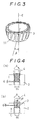
- An inner ring 1 embodying the inner rotation body is mounted firmly on a shaft 4, which may be the input shaft or the output shaft of the coupling, by e.g., a key engagement 5.
- An outer ring 2 embodying the outer rotation body is disposed facing the inner ring 1 to form a raceway 9 between them.
- a plurality of rollers 3 embodying the intermediate rotation body are, as shown in Fig. 3, disposed in the raceway 9 slanting to a plane including a central axis 6 of the inner ring 1 (or the output or input shaft 4) at angle ⁇ (e.g., 15°).
- a bearing 13 On one side (e.g., left side as shown in Fig. 1) of the inner ring 1 (which is also at the left side end of the outer ring 2), a bearing 13 is mounted to carry the radial load of the output shaft or the input shaft and the thrust load of a spring plate 7 embodying the energizing means (Fig. 6). On the bearing 13 is mounted a housing 14 embodying the power transmission rotation body in order to transmit a torque to the output shaft of the coupling. The housing 14 can rotate around the bearing 13, but the axial movement of the housing 14 is restricted by the bearing 13, so that it remains at a constant position relative to the inner ring 1.
- the outer ring 2 is connected with the housing 14 so as to rotate integrally, but movably in the axial direction, through a torque transmission means such as a torque transmission pin 15, or an involute spline 16 (Fig. 6) or a ball spline (not shown).
- the housing 14 can be an input side or output side of the coupling by inserting mounting bolts into a flange 14a for connection.
- the spring plate 7 (Fig. 6) or a coil spring used for energizing means is located in between the housing 14 and the outer ring 2, to push away the outer ring 2 all the time to a direction so as to narrow a gap of the raceway 9 (in Fig. 1, left to right).
- the inner ring 1 is provided with a flange 10, to restrict and axial movement of the rollers 3, when the inner ring 1 rotates in the direction for losing the transmission torque and the rollers 3 advance so far in the axial direction in the gap of the raceway 9 as to widen the gap.
- rollers 3 are arranged on the inner ring 1 so as to slant to a section including the axis 6 thereof by an angle of ⁇ .
- the rollers 3 are retained in place by a retainer 11 to keep off each other.
- This configuration can prevent adjacent rollers 3 (each rotating about its axis in a same direction) from running against each other with a relative tangential speed in an opposite direction, resulting in a smooth rotation of the rollers 3 about their axes and a smooth revolution thereof around the inner ring 1.
- a convexed portion of a roller 3 contacts with a concaved portion of the outer ring raceway track 2a, while a convexed portion of a roller 3 contacts with a convexed portion of the inner ring raceway track 1a.
- a contact surface pressure between the rollers 3 and the inner ring raceway track 1a is larger than that between the rollers 3 and the outer ring raceway track 2a and, therefore, the rollers are guided by the inner ring raceway track 1a.
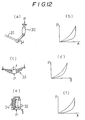
- Figs. 4 (a) and 4 (b) are schematic diagrams showing the action of the torque absorber introduced by such movements of the inner and rings 1 and 2 and the rollers 3: The action is similar to the one caused by the taper screw shown in Fig. 4 (a).
- Fig. 4 (b) when the screw (or roller) 3 or the shaft 4 is rotated in the direction A, the outer ring 2 advances toward the direction C through the roller 3, thus causing the outer ring 2 to be locked with the shaft 4 as if a rotated taper screw is locked with the mating thread.
- a lead angle ⁇ and a taper angle ⁇ 1 of the taper screw correspond to a twist lead angle ⁇ ' (equivalent to the slant angle ⁇ of the roller 3) and a contact angle ⁇ '1 of the torque absorber.
- Fig. 5 is characteristic curves showing typical changes in transmission torque in the embodiment.
- the abscissa in Fig. 5 shows an axial displacement ⁇ or a locking action angle ⁇ of the outer ring 2, or a relative torsional angle between the inner and outer rings 1 and 2.
- the ordinate shows a torque T transmitted between the inner and outer rings 1 and 2 or the shaft 4 and the housing 14 corresponding to value of ⁇ or ⁇ .
- a displacement ⁇ is in a linear proportion with a corresponding torsional angle ⁇ .
- a curve "a" in Fig. 5 shown how a transmission torque increases when the shaft 4 or the inner ring 1 is rotated in a direction of arrow A in Fig. 2, that is in a direction to lock the inner and outer rings 1 and 2.
- the magnitude of transmission torque between the inner and outer rings 1 and 2 is proportional to the magnitude of a wedge action caused by the rollers 3 caught in between the inner and outer rings 1 and 2, which may take place when the outer ring 2 is twisted relatively to the inner ring 1 and advances toward the inner ring 1 so as to narrow the gap of the raceway.
- a transmission torque T has a characteristics like a non-linear torsional spring. More particularly, even if a sudden large torque is loaded to the output side, first there may take place a large angular displacement to absorb the shock torque, and then a transmission torque may rise gradually up to the rated transmission torque capacity T1 as shown in Fig. 5. P1 designates a point of the rated transmission torque.
- the curve "b" shows how a transmission torque will drop when output load is suddenly lost from the rated torque T1. More particularly, first the rated torque T1 will drop sharply, and then gradually approaches zero, when the shaft 4 or the inner ring 1 may turn in the reverse direction (in a direction opposite to arrow A in Fig. 2). In this case, due to a sudden loss of the wedge action, when axial displacement ⁇ or relative torsional angle ⁇ be reduced slightly, a transmission torque T amy drop more sharply (like a curved segment P1P2) than when it rises, then gradually approaches near zero or point P3.
- the displacement ⁇ or the torsion angle ⁇ may change in an area enclosed by the curves "a" and "b" corresponding to the magnitude of the varying torque to absorb the torque variation.
- the coupling when first a torque is loaded along the curve "a" from P0 to P1, and then removed along the curve "b" from P1 to P0, during the time when torque is added, the coupling stores a strain energy corresponding to the area enclosed by a line P0 - curve "a" - P1 - ⁇ 1 - P0, while during the time when torque is removed, the coupling feedbacks to the power system a strain energy corresponding to the area enclosed by a line P0 - curve "b” - P1 - ⁇ 1 - P0. Therefore, after all, an energy corresponding to the area enclosed by the curves "a” and "b" has been absorbed in the coupling.
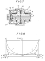
- Fig. 6 is a sectional view showing another cmbodiment of a torque variation absorbing coupling according to the present invention.
- This embodiment uses an involute spline 16 rather than the torque transmission pin 15 shown in Fig. 1, as a torque transmission means.
- Fig. 7 is a sectional view showing a torque variation absorbing power transmission system as claimed in claim 2:
- Main components in the power transmission system are two sets of the torque variation absorbing couplings shown in Fig. 6.
- a pair of the torque variation absorbing couplings 17, 17' are so arranged as to face each other in a direction of a common axis 6.
- Housings 14, 14' of the torque variation absorbing couplings 17, 17' are connected by bolting 19 via a spacer 18 to be rotated like a single block.
- An input shaft (or an output shaft) as a power transmission system is connected to inner rings 1, 1' facing each other with a shaft fixing flange 20.
- a mounting flange 21 is provided on the housing 14', to which the output shaft (or the input shaft) is fixed.
- such a torque transmission means as a torque transmission pin 15 or a ball spline may be used in place of the involute spline 16.
- this power transmission system since the action described above referring to Fig. 5 can work either in the normal rotation direction of a power system or the reverse rotation direction, this power transmission system can be used in a power system which rotates in two (normal and reverse) directions.
- Fig. 8 is characteristic curves showing typical changes in transmission torque in the embodiment shown in Fig. 7; In this case also, like the case shown in Fig. 5, let us assume that a spring 7 does not contribute to the torque transmission.
- the torque variation absorbing couplings 17, 17' When the torque variation absorbing couplings 17, 17' rotate in the normal direction, and their torques both start at an initial position of point P0 and when the torque variation absorbing coupling 17 is increasing its transmission torque along a curve "a" from P0 to P1, the torque variation absorbing coupling 17' may rotate free without transmitting any torque, while keeping the position of point P0 because of the pushing force of the spring 7.
- a possible torque variation is absorbed only by the torque variation absorbing coupling 17, thus transmitting a smooth torque from the input shaft to the output shaft.
- the torque variation absorbing coupling 17 may rotate free without transmitting any torque, while keeping the position of point P0.
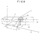
- Figs. 9 to 11 are explanatory drawings for determining the raceway surface shapes in the case of cylindrical rollers 3.
- Fig. 9 is a perspective view showing X-Y-Z coordinates, in which a roller 3 is so placed that its axis 3a passes through the Y axis a distance F away from the origin O, in parallel to the X-Z plane, slanting to the X-Y plane at an angle of ⁇ .
- the X axis represent the common axis 6 of the inner and outer rings 1 and 2.
- the section 3b of the roller 3 shows a section cut by a parallel plane to the Y-Z plane passing the X axis at an arbitrary position x.
- Points Uc and U'c are respectively intersections with the X axis and the X-Z plane, of perpendiculars drawn from the center Pc of the cross section to the X axis and the X-Z plane.
- the line 3a' passing the origin O and the point U'c is a projected line of the roller axis 3a to the X-Z plane, forming an angle ⁇ with the X axis.
- Fig. 10 is a drawing for explaining how the rings 1 and 2 come into contact with the roller 3 arranged as above.
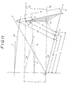
- Fig. 11 is an enlarged view showing related portions to the determination of these functions.
- segment QPc (equal to R) is at right angle with the center axis 3a of the roller 3, and the point U'c is an intersection of the perpendicular from the point Pc to the X-Z plane therewith, segment U'cQ is at right angle with the axis 3a'.
- the above embodiments have a cylindrical rolling surface of the rollers 3, but may be replaced with conical, hourglass or convex drum shape of rolling surface.
- the rollers 3 are brought into line contact with the inner and outer rings 1 and 2.
- the inner and outer raceway track surfaces are designed to be mono-hyperboloid of revolution like the case of cylindrical rollers.
- the inner ring is formed into a cylindrical shape and the outer ring is into a combination of elliptic and hyperbolic surfaces of revolution.
- the outer ring is formed into a cylindrical shape and the inner ring is into a combination of elliptic and hyperbolic surfaces of revolution.
- the raceway is formed in between the inner and outer rotation bodies, and the intermediate rotation body is arranged slanted to the inner and outer rotation bodies so as to have a line contact with the raceway track, thereby utilizing a tapered screw action to be produced among them. Therefore, the power transmission system including the torque variation absorbing coupling (for which a power system rotates only in a single direction) can absorb a large torque variation by the small-sized and simple-configured (like rolling bearing) coupling.
- the power transmission system as claimed in claim 2 (including the torque variation absorbing couplings): At least two sets of the torque variation absorbing couplings are arranges so as to face each other, thereby constituting a torque variation absorbing power transmission system. Therefore, the power transmission system including the torque variation absorbing couplings (for which a power system rotates in two normal and reverse directions) can absorb a large torque variation by the small-sized and simple-configured (like rolling bearing) couplings.
Landscapes
- Engineering & Computer Science (AREA)
- General Engineering & Computer Science (AREA)
- Mechanical Engineering (AREA)
- Friction Gearing (AREA)
- Rolling Contact Bearings (AREA)
Applications Claiming Priority (1)
| Application Number | Priority Date | Filing Date | Title |
|---|---|---|---|
| PCT/JP1991/001075 WO1993004294A1 (en) | 1991-08-13 | 1991-08-13 | Coupling to absorb torque variation |
Publications (2)
| Publication Number | Publication Date |
|---|---|
| EP0551515A1 true EP0551515A1 (en) | 1993-07-21 |
| EP0551515A4 EP0551515A4 (enExample) | 1994-01-19 |
Family
ID=14014541
Family Applications (1)
| Application Number | Title | Priority Date | Filing Date |
|---|---|---|---|
| EP91914202A Withdrawn EP0551515A1 (en) | 1991-08-13 | 1991-08-13 | Coupling to absorb torque variation |
Country Status (5)
| Country | Link |
|---|---|
| EP (1) | EP0551515A1 (enExample) |
| KR (1) | KR930702627A (enExample) |
| AU (1) | AU651611B2 (enExample) |
| NO (1) | NO931240L (enExample) |
| WO (1) | WO1993004294A1 (enExample) |
Cited By (1)
| Publication number | Priority date | Publication date | Assignee | Title |
|---|---|---|---|---|
| RU2238454C1 (ru) * | 2003-04-08 | 2004-10-20 | Ульяновский государственный технический университет | Демпфер колебаний вращающихся тел |
Family Cites Families (6)
| Publication number | Priority date | Publication date | Assignee | Title |
|---|---|---|---|---|
| GB324792A (en) * | 1929-01-17 | 1930-02-06 | Humfrey Sandberg Company Ltd | Improvements relating to clutch devices |
| JPS5121093B1 (enExample) * | 1968-03-29 | 1976-06-30 | ||
| JPS5852092B2 (ja) * | 1975-03-31 | 1983-11-19 | 信夫 高田 | イツポウクラツチ |
| JPS6023664A (ja) * | 1983-07-16 | 1985-02-06 | Ntn Toyo Bearing Co Ltd | 速度調整装置 |
| GB8501822D0 (en) * | 1985-01-24 | 1985-02-27 | Castens R R | Clutches |
| US5035309A (en) * | 1989-05-08 | 1991-07-30 | Nobuo Takada | Rolling-contact bearing type clutch |
-
1991
- 1991-08-13 KR KR1019930701114A patent/KR930702627A/ko not_active Ceased
- 1991-08-13 EP EP91914202A patent/EP0551515A1/en not_active Withdrawn
- 1991-08-13 WO PCT/JP1991/001075 patent/WO1993004294A1/ja not_active Ceased
- 1991-08-13 AU AU83174/91A patent/AU651611B2/en not_active Ceased
-
1993
- 1993-03-31 NO NO93931240A patent/NO931240L/no unknown
Cited By (1)
| Publication number | Priority date | Publication date | Assignee | Title |
|---|---|---|---|---|
| RU2238454C1 (ru) * | 2003-04-08 | 2004-10-20 | Ульяновский государственный технический университет | Демпфер колебаний вращающихся тел |
Also Published As
| Publication number | Publication date |
|---|---|
| KR930702627A (ko) | 1993-09-09 |
| NO931240D0 (no) | 1993-03-31 |
| NO931240L (no) | 1993-06-03 |
| WO1993004294A1 (en) | 1993-03-04 |
| AU651611B2 (en) | 1994-07-28 |
| EP0551515A4 (enExample) | 1994-01-19 |
| AU8317491A (en) | 1993-03-16 |
Similar Documents
| Publication | Publication Date | Title |
|---|---|---|
| EP0396992B1 (en) | Rolling-contact bearing type clutch | |
| US3945270A (en) | Friction drive transmission | |
| US5482144A (en) | Three-dimensional roller locking sprags | |
| US5928083A (en) | One-way over-running flex coupling | |
| US8167760B2 (en) | Toroidal continuously variable transmission unit and continuously variable transmission | |
| US5381879A (en) | Torque absorber | |
| US5518094A (en) | Clutch/brake having rectangular-area-contact 3D locking sprags | |
| US4481842A (en) | Torque limit drive transmission | |
| EP0551516B1 (en) | Roller bearing | |
| US3698208A (en) | Flexible coupling | |
| EP0551515A1 (en) | Coupling to absorb torque variation | |
| CA1286617C (en) | Clutches | |
| US3230741A (en) | Coupling device | |
| US3598210A (en) | Clutch comprising a helical spring actuator | |
| CA2093920A1 (en) | Torque variation absorbing coupling | |
| JP3031939B2 (ja) | トルク変動吸収カップリング | |
| US4620455A (en) | Traction roller transmission | |
| US6733415B2 (en) | Power roller for a toroidal continuously variable transmission | |
| US3365982A (en) | Mechanical drive mechanism | |
| Aliukov et al. | Inertial continuously variable transmissions and ways to improve their performance | |
| JP3031942B2 (ja) | トルクリミッタ | |
| US3058556A (en) | Transmission | |
| JP5352769B2 (ja) | ローラークラッチ | |
| JPH0342240B2 (enExample) | ||
| CA2093648A1 (en) | Antifriction roller bearing |
Legal Events
| Date | Code | Title | Description |
|---|---|---|---|
| PUAI | Public reference made under article 153(3) epc to a published international application that has entered the european phase |
Free format text: ORIGINAL CODE: 0009012 |
|
| AK | Designated contracting states |
Kind code of ref document: A1 Designated state(s): AT CH DE ES FR GB GR IT LI NL SE |
|
| RBV | Designated contracting states (corrected) |
Designated state(s): AT CH DE ES FR GB IT LI NL SE |
|
| 17P | Request for examination filed |
Effective date: 19930723 |
|
| A4 | Supplementary search report drawn up and despatched |
Effective date: 19931203 |
|
| AK | Designated contracting states |
Kind code of ref document: A4 Designated state(s): AT CH DE ES FR GB GR IT LI NL SE |
|
| 17Q | First examination report despatched |
Effective date: 19940316 |
|
| STAA | Information on the status of an ep patent application or granted ep patent |
Free format text: STATUS: THE APPLICATION HAS BEEN WITHDRAWN |
|
| RAP1 | Party data changed (applicant data changed or rights of an application transferred) |
Owner name: THK MENT RESEARCH CO., LTD. |
|
| RIN1 | Information on inventor provided before grant (corrected) |
Inventor name: TAKATA, NOBUO |
|
| 18W | Application withdrawn |
Withdrawal date: 19940927 |