EP0551008A1 - Control apparatus for use in automotive air conditioning system - Google Patents
Control apparatus for use in automotive air conditioning system Download PDFInfo
- Publication number
- EP0551008A1 EP0551008A1 EP92311824A EP92311824A EP0551008A1 EP 0551008 A1 EP0551008 A1 EP 0551008A1 EP 92311824 A EP92311824 A EP 92311824A EP 92311824 A EP92311824 A EP 92311824A EP 0551008 A1 EP0551008 A1 EP 0551008A1
- Authority
- EP
- European Patent Office
- Prior art keywords
- evaporator
- value
- temperature
- compressor
- conditioning system
- Prior art date
- Legal status (The legal status is an assumption and is not a legal conclusion. Google has not performed a legal analysis and makes no representation as to the accuracy of the status listed.)
- Granted
Links
Images

Classifications
-
- B—PERFORMING OPERATIONS; TRANSPORTING
- B60—VEHICLES IN GENERAL
- B60H—ARRANGEMENTS OF HEATING, COOLING, VENTILATING OR OTHER AIR-TREATING DEVICES SPECIALLY ADAPTED FOR PASSENGER OR GOODS SPACES OF VEHICLES
- B60H1/00—Heating, cooling or ventilating devices
- B60H1/32—Cooling devices
- B60H1/3204—Cooling devices using compression
- B60H1/3205—Control means therefor
-
- F—MECHANICAL ENGINEERING; LIGHTING; HEATING; WEAPONS; BLASTING
- F25—REFRIGERATION OR COOLING; COMBINED HEATING AND REFRIGERATION SYSTEMS; HEAT PUMP SYSTEMS; MANUFACTURE OR STORAGE OF ICE; LIQUEFACTION SOLIDIFICATION OF GASES
- F25B—REFRIGERATION MACHINES, PLANTS OR SYSTEMS; COMBINED HEATING AND REFRIGERATION SYSTEMS; HEAT PUMP SYSTEMS
- F25B49/00—Arrangement or mounting of control or safety devices
- F25B49/02—Arrangement or mounting of control or safety devices for compression type machines, plants or systems
- F25B49/022—Compressor control arrangements
Definitions
- the present invention relates to an automotive air conditioning system, and more particularly, to a control apparatus for controlling an operation of the automotive air conditioning system which includes an externally controlled variable capacity type refrigerant compressor.
- Control apparatuses for controlling an operation of an automotive air conditioning system which includes an externally controlled variable capacity type refrigerant compressor are well known in the art.
- temperature T'e of the air immediately downstream an evaporator is controlled as indicated by dashed lines in Figures 5 and 6.
- a control point of pressure in a compressor suction chamber is maintained at the minimum boundary value 1.0 kg/cm2 G so as to quickly drop the temperature T'e by means of outputting one electric signal having one certain amperage Ipl from the control apparatus to an externally controlled variable capacity control mechanism of the compressor.
- the control point of pressure in the compressor suction chamber is varied so as to converge the temperature Te at the set temperature Tset by means of outputting another electric signal having various amperages which is produced by the proportional control action of the control apparatus.
- the proportional control action is initialized by the one certain amperage Ipl.
- the temperature Te of the air immediately downstream the evaporator overshoots from the set temperature Tset by a great value so that it takes a long time to converge the temperature T'e at the set temperature Tset. Accordingly, the passenger compartment of the automobile can not adequately air conditioned in the initial operation stage of the automotive air conditioning system.
- an object of the present invention to provide an automotive air conditioning system which can adequately air condition a passenger compartment of an automobile in an initial operation stage thereof.
- the automotive air conditioning system includes a refrigerant circuit having a refrigerant compressor with an externally controlled variable capacity control mechanism and an evaporator connected to a suction chamber of the refrigerant compressor, and a fan associated with the evaporator so as to move air through an exterior surface of the evaporator, and a control mechanism for controlling an operation thereof.
- the control mechanism includes the following devices.
- a sensing device senses temperature of air immediately downstream the evaporator.
- a first determining device determines a first value of a control point of pressure in the suction chamber of the compressor according to the temperature of air immediately downstream the evaporator at a time immediately before the operation of the refrigerant circuit is initiated.
- a comparing device compares the temperature of air immediately downstream the evaporator during the operation of the refrigerant circuit is higher than one certain value which is higher than a set value.
- a second determining device determines a second value of the control point of pressure in the suction chamber of the compressor, according to a thermal gradient with respect to a time in a situation where the temperature of air immediately downstream the evaporator immediately before reaches the one certain value from a higher value side thereof.
- a carrying out device carries out operation of proportional control action which includes a value obtained by subtracting the temperature of air immediately downstream the evaporator during the operation of said refrigerant circuit from the set temperature.
- a changing device changes a first situation in which the control point of pressure in the suction chamber of the compressor is adjusted to be maintained at the first value to a second situation in which the control point of pressure in the suction cheer of the compressor is adjusted to be varied by a result of operation of the proportional control action when the temperature of air immediately downstream the evaporator during the operation of the refrigerant circuit is equal to or lower than the one certain value.
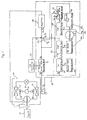
- the automotive air conditioning system includes refrigerant circuit 10 and control apparatus 20 which controls an operation of the automotive air conditioning system.
- Refrigerant circuit 10 includes refrigerant compressor 11 with an externally controlled variable capacity control mechanism (not shown), condenser 12, expansion device 13 and evaporator 14 these which are connected in series.
- Electromagnetic clutch 111 is fixedly mounted on compressor 11, and intermittently transmits the power derived from an external power source, such as an engine 15 of an automobile to a drive shaft of the compressor 10 in order to intermittently operate the compressor 10.
- Refrigerant circuit 10 further includes condenser fan 121 which is associated with condenser 12 so as to pass the air through an exterior surface of condenser 12 by virtue of operation thereof, and evaporator fan 141 which is associated with evaporator 14 so as to pass the air through an exterior surface of evaporator 14 by virtue of operation thereof.
- Condenser fan 121 and evaporator fan 141 are operated by receiving an electric power from DC battery 16 installed in an engine compartment of the automobile.
- Control apparatus 20 includes thermosensor 17, primary initial value generating device 21, fist comparing device 23, boundary value generating device 24, second comparing device 25, set value generating device 26a, subtracter 26b, first operation device 28, second operation device 26c, secondary initial value generating device 29, second switching device 27, and amplifier 30 theses which are described in detail below.
- Thermosensor 17 is associated with evaporator 14, of which an outlet is connected to a suction chamber of compressor 11, so as to detect temperature Te of the air immediately downstream evaporator 14 at a predetermined very short time interval ⁇ T, and generates first electric signal S1 representing a detected temperature Te.
- Thermosensor 17 further detects temperature Tea of the air immediately downstream evaporator 14 at a time immediately before the operation of compressor 11, i.e., the operation of the refrigerant circuit 10 is initiated, and generates second electric signal S2 which represents the detected temperature Tea of the air immediately downstream evaporator 14 at a time immediately before the operation of refrigerant circuit is initiated.
- Thermosensor 17 is connected to a primary initial value generating device 21 so as to send second electric signal S2 to primary initial value generating device 21.
- Primary initial value generating device 21 is further connected to first switching device 22 which is turned on and off so as to initiate and terminate the operation of the automotive air conditioning system.
- the first switching device 21 When the air in a passenger compartment of the automobile is demanded to be cooled, the first switching device 21 is turned on. As the first switching device 21 is turned on, an operation of evaporator fan 141 and condenser fan 121 is initiated, and concurrently, an operation of control apparatus 20 is initiated so that second switching device 27 operates to connect a primary initial value generating device 21 to amplifier 30 through first terminal 27a thereof. After this, an electromagnetic coil (not shown ) of electromagnetic clutch 111 is energized so that an operation of compressor 11 is initiated.
- compressor 11 When compressor 11 operates, a condensation of the compressed gaseous refrigerant at condenser 12 with heat exchanging, an expansion of the condensed refrigerant at expansion device 13, and an evaporation of the expanded refrigerant at evaporator 14 with heat exchanging are successively carried out. Thereafter, the vaporized refrigerant in evaporator 14 returns to compressor 11. As long as compressor 11 operates, the above-mentioned successive operational manners are repeated.
- primary initial value generating device 21 processes second electric signal S2 sent from thermosensor 17 to generate third electric signal S3 of which amperage Ia varies in response to changes in the detected temperature Tea.
- third electric signal S3 is described in detail below.
- amperage Ia of third electric signal S3 varies in a range between the first constant values Ic1 which intends to adjust the control point of pressure in a compressor suction chamber at 2.5 kg/cm2 G and a third constant value Ic3 which intends to adjust the control point of pressure in the compressor suction chamber at 1.7 kg/cm2 G.
- First comparing device 23 is connected to thermosensor 17 so as to receive second electric signal S2 from thermosensor 17. First comparing device 23 is further connected to a boundary value generating device 24 in which fourth electric signal S4 representing the predetermined second boundary value T2 is generated. First comparing device 23 processes second electric signal S2 sent from thermosensor 17 and fourth electric signal S4 sent from boundary value generating device 24 so as to compare whether the detected temperature Tea is equal to or higher than the predetermined second boundary value T2.
- first comparing device 23 In this comparing process, if the detected temperature Tea is equal to or higher than the predetermined second boundary value T2, first comparing device 23 generates a fifth electric signal S5 representing the comparing result in which the detected temperature Tea is equal to or higher than the predetermined second boundary value T2. On the other hand, if the detected temperature Tea is lower than the predetermined second boundary value T2, first comparing device 23 generates a sixth electric signal S6 representing the comparing result in which the detected temperature Tea is lower than the predetermined second boundary value T2.
- Second comparing device 25 is connected to thermosensor 17 so as te receive first electric signal S1 representing the detected temperature Te. Second comparing device 25 is further connected to a set value generating device 26a in which a seventh electric signal S7 representing a third boundary value T3 which is higher than a set temperature Tset of the air immediately downstream evaporator 14 by a predetermined slight amount of value ⁇ Tset is generated. Usually, the third boundary value T3 is in a range between the predetermined first and second boundary values T1 and T2. Second comparing device 25 processes first electric signal C1 sent from thermosensor 17 and the seventh electric signal S7 sent from the set value generating device 26a so as to compare whether the detected temperature Te is higher than the third boundary value T3.
- second comparing device 25 In this comparing process, if the detected temperature Te is higher than the third boundary value T3, second comparing device 25 generates an eighth electric signal S8 representing the comparing result in which the detected temperature Te is higher than the third boundary value T3. On the other hand, if the detected temperature Te is equal to or lower than the third boundary value T3, second comparing device 25 generates an ninth electric signal S9 representing the comparing result in which the detected temperature Te is equal to or lower than the third boundary value T3.
- First operation device 28 is connected to thermosensor 17 so as to receive the first electric signal S1 representing the detected temperature Te from thermosensor 17.
- First operation device 28 processes the first electric signal S1 so as to carry out an operation of the following equation.
- ⁇ (n) (Te(n) - Te(n-m))/ ⁇ t (1)
- the appended symbols (n) and (n-m) indicate the ordinal number of the detected temperature Te.
- ⁇ (n) is a thermal gradient of the detected temperature Te(n) with respect to a predetermined short time period ⁇ t in a time immediately before the detected temperature Te(n) reaches to the third boundary value T3 from a higher value side of the third boundary value T3.
- Te(n-m) m is a quotient of ⁇ t/ ⁇ T, but is a natural number because that ⁇ t is predetermined to be a multiple of ⁇ T.
- First operation device 28 generates a tenth electric signal S10 representing the thermal gradient ⁇ (n) and is connected to a secondary initial value generating device 29 so as to output the tenth electric signal S10 to secondary initial value generating device 29.
- Secondary initial value generating device 29 is further connected to primary initial value generating device 21 so as to receive third electric signal S3 from primary initial value generating device 21.
- Secondary initial value generating device 29 is still further connected to first comparing device 23 so as to receive fifth and sixth electric signals S5 and S6 from the first comparing device 23.
- Secondary initial value generating device 29 processes fifth and sixth electric signals S5 and S6 sent from first comparing device 23, third electric signal S3 sent form primary initial value generating device 21, and tenth electric signal S10 sent from first operation device 28.
- secondary initial value generating device 29 when secondary initial value generating device 29 receives the sixth electric signal S6 representing the comparing result in which the detected temperature Tea is lower than the predetermined second boundary value T2, secondary initial value generating device 29 generates an eleventh electric signal S11 which is identical to the third electric signal S3 having amperage Ia which varies in response to changes in the detected temperature Tea.
- secondary initial value generating device 29 receives the fifth electric signal S5 representing the comparing result in which the detected temperature Tea is equal to or higher than the predetermined second boundary value T2
- secondary control value generating device 29 when secondary initial value generating device 29 receives the fifth electric signal S5 representing the comparing result in which the detected temperature Tea is equal to or higher than the predetermined second boundary value T2, secondary control value generating device 29 generates a twelfth electric signal S12 of which amperage Ib varies in response to changes in the thermal gradient ⁇ (n).
- amperage Ib of twelfth electric signal S12 is maintained at a fifth constant value Ic5 which is equal to the first constant value Ic1 shown in Figure 2 and therefore, intends to control the control point of pressure in the compressor suction chamber pressure at 2.5 kg/cm2 G.
- amperage Ib of twelfth electric signal S12 varies in a range between the fourth and fifth constant values Ic4 and Ic5 so that the control point of pressure in the compressor suction chamber pressure is intended to be varied within a range between 2.5 kg/cm2 G and 1.5 kg/cm2 G.
- Secondary initial value generating device 29 is furthermore connected to second operation device 26c so as to send the eleventh and twelfth electric signals S11 and S12 to second operation device 26c.
- the set value generating device 26a further generates a thirteenth electric signal S13 which represents the set temperature Tset of the air immediately downstream evaporator 14.
- the set value generating device 26a is further connected to subtracter 26b so as to send the thirteenth electric signal S13 to subtracter 26b therefrom.
- Subtracter 26b is further connected to thermosensor 17 so as to receive the first electric signal S1 representing the detected temperature Te.
- the subtracter 26b generates a fourteenth electric signal S14 representing ⁇ Tv and is connected to second operation device 26c so as to send the fourteenth electric signal S14 to second operation device 26c.
- Second operation device 26c processes the eleventh and twelfth electric signals S11 and S12 sent from secondary initial value generating device 29, and fourteenth electric signal S14 sent from subtracter 26b so as to carry out the operation of the following equation.
- I(l) I(l-l) + Kp( ⁇ Tv(l) - ⁇ Tv(l-1)) (3)
- Kp is a factor of proportionality.
- Appended symbols (l) or (l-l) indicate the ordinal number of the values processed in the second operation device 26c.
- Second operation device 26a When second operation device 26c receives the eleventh electric signal S11 while the appended symbol (l) is 1, the term I(l-1) becomes Ia. On the other hand, when second operation device 26a receives the twelfth electric signal S12 while the appended symbol (l) is 1, the term I(l-l) beams Ib. Second operation device 26a generates a fifteenth electric signal S15 having various amperages I(l).
- Second switching device 27 receives the eighth and ninth electric signals S8 and S9 sent from second comparing device 25.
- second switching device 27 receives ninth electric signal S9, that is, when the detected temperature Te is equal to or lower than the third boundary value T3
- second switching device 27 operates to connect second operation device 26c to amplifier 30 through second terminal 27b of second switching device 27 so that amperage I(l) of the fifteenth electric signal S15 is amplified to be amperage G I (I(l)) by amplifier 30.
- G I is the gain given by virtue of operation of amplifier 30.
- the electric current having amplified amperage G I (I(l)) is supplied to a solenoid (not shown) of the externally controlled variable capacity control mechanism of the compressor.
- second switching device 27 receives eighth electric signal S8, that is, when the detected temperature Te is higher than the third boundary value T3, the connection between primary initial value generating device 21 and amplifier 30 is maintained so that amperage Ia of the third electric signal S3 is amplified to be amperage G I (Ia) by amplifier 30.
- the electric current having amplified amperage G I (Ia) is supplied to the solenoid (not shown) of the externally controlled variable capacity control mechanism of the compressor.
- set value generating device 26a, subtracter 26b and second operation device 26c form a control device 26 which carries out a proportional control action.
- step 201 when the air of the passenger compartment of the automobile is demanded to be cooled, the first switching device 22 is turned on so as to initiate the operation of the automotive air conditioning system in step 201.
- step 201 proceeds to step 202.
- step 202 the operation of condenser fan 121 and evaporator fan 141 is initiated, and concurrently, the operation of control apparatus 20 is initiated so that second switching device 27 operates to connect primary initial value generating device 21 to amplifier 30 through first terminal 27a thereof.
- step 202 proceeds to step 203.
- step 203 the second electric signal S2 representing the detected temperature Tea is sent to primary initial value generating device 21 and first comparing device 23 from thermosensor 17.
- step 203 proceeds to step 204.
- step 204 primary initial value generating device 21 processes the second electric signal S2 so as to generate third electric signal S3 having various amperages Ia shown in Figure 2.
- step 204 proceeds to step 205.
- step 205 the operation of compressor 11 is initiated by receiving the power from the engine of the automobile through electromagnetic clutch 111 while the third electric signal S3 is sent from primary initial value generating device 21 to amplifier 30 through first terminal 27a of second switching device 27 so that the electric current having the amplified amperage G I (Ia) is supplied to the solenoid of the externally controlled capacity control mechanism of the compressor so as to adjust the control point of pressure in the compressor suction chamber to be maintained at one certain value. Furthermore, if the detected temperature Tea is equal to or higher than the predetermined second boundary value T2, amperage Ia of third electric signal S3 is maintained at the second constant value Ic2 so that the control point of pressure in the compressor suction chamber is adjusted to be maintained at 1.0 kg/cm2 G.
- step 205 proceeds to step 206.
- the second comparing device 25 compares whether the detected temperature Te is higher than the third boundary value T3. If the detected temperature Te is higher than the third boundary value T3, step 206 returns to step 205. On the other hand, if the detected temperature Te is equal to or lower than the third boundary value T3, step 206 proceeds to step 207.
- second switching device 27 operates to connect second operation device 26c to amplifier 30 through second terminal 27a thereof, and concurrently, the comparing result of first comparing device 23 is recalled.
- step 207 proceeds to step 208.
- step 208 if the recalled comparing result of first comparing device 23 shows that the detected temperature Tea is lower than the predetermined second boundary value T2, step 208 proceeds to step 209.
- step 209 eleventh electric signal S11 which is identical to third electric signal S3 is sent to second operation device 26c from secondary initial value generating device 29.
- step 209 proceeds to step 212.
- step 208 proceeds to step 210.
- step 210 the operation of equation (1) is carried out in first operation device 28 so as to generate tenth electric signal S10.
- step 210 proceeds to step 211.
- the tenth electric signal S10 is processed in secondary initial value generating device 29 so as to generate twelfth electric signal S12.
- the twelfth electric signal S12 is sent to second operation device 26c from secondary initial value generating device 29.
- step 211 proceeds to step 212.
- step 212 the operation of equation (3) is carried out in second operation device 26c so as to generate fifteenth electric signal S15 having various amperage I(l), and fifteenth electric signal S15 is sent to amplifier 30 through second terminal 27b of second switching device 27 to be amplified its amperage. Then, the electric current having amplified amperage G I (I(l)) is supplied to the solenoid of the externally controlled variable capacity control mechanism of the compressor 11 so as to adjust the control point of pressure in the compressor suction chamber at various values so that the temperature Te is converged at the set temperature Tset. Step 212 continuously goes on until the operation of the automotive air conditioning system is terminated.
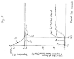
- Figures 5 illustrates a cool-down characteristic in the initial operation stage of the automotive air conditioning system in a situation where the detected temperature Te is equal to or higher the predetermined second boundary value T2. More specifically, in Figure 5, the cool-down characteristic of the automotive air conditioning system in accordance with one embodiment of the present is indicated by a solid line.
- the control point of pressure in the compressor suction chamber is adjusted by the proportional control action which is initialized by twelfth electric signal S12 of which amperage Ib is a relatively larger value. Accordingly, in the initial operation stage of the automotive air conditioning system, the temperature Te of the air immediately downstream evaporator 14 quickly drops without overshooting from the set temperature Tset while is quickly and effectively converged at the set temperature Tset.
- the passenger compartment of the automobile can be more adequately air conditioned in the initial operation stage of the automotive air conditioning system.
- Figure 6 illustrates a cool-down characteristic of the automotive air conditioning system in accordance with one embodiment of the present invention in a situation where temperature Tea is lower than the predetermined second boundary value T2. More specifically, in Figure 6, the cool-down characteristic of the automotive air conditioning system in accordance with one embodiment of the present is indicated by a solid line.
- the control point of pressure in the compressor suction chamber is adjusted by the proportional control action which is initialized by eleventh electric signal S11 which is identical to the third electric signal S3. Accordingly, in the initial operation stage of the automotive air conditioning system, the temperature Te of the air immediately downstream evaporator 14 gently drops without overshooting from the set temperature Tset while is quickly and effectively converged at the set temperature Tset.
- the passenger compartment of the automobile can be more adequately air conditioned in the initial operation stage of the automotive air conditioning system.
Landscapes
- Engineering & Computer Science (AREA)
- Physics & Mathematics (AREA)
- Thermal Sciences (AREA)
- Mechanical Engineering (AREA)
- General Engineering & Computer Science (AREA)
- Air-Conditioning For Vehicles (AREA)
Abstract
Description
- The present invention relates to an automotive air conditioning system, and more particularly, to a control apparatus for controlling an operation of the automotive air conditioning system which includes an externally controlled variable capacity type refrigerant compressor.
- Control apparatuses for controlling an operation of an automotive air conditioning system which includes an externally controlled variable capacity type refrigerant compressor are well known in the art.
- According to one conventional control apparatus, in the initial operation stage of the automotive air conditioning system, temperature T'e of the air immediately downstream an evaporator is controlled as indicated by dashed lines in Figures 5 and 6.
- With reference to Figures 5 and 6, from a time t0 when the operation of a refrigerant circuit is initiated to a time t'1 when the temperature T'e drops to a certain value T3 which is slightly greater than a set temperature Tset, a control point of pressure in a compressor suction chamber is maintained at the minimum boundary value 1.0 kg/cm² G so as to quickly drop the temperature T'e by means of outputting one electric signal having one certain amperage Ipl from the control apparatus to an externally controlled variable capacity control mechanism of the compressor. Once the temperature T'e drops to the certain value T3, the control point of pressure in the compressor suction chamber is varied so as to converge the temperature Te at the set temperature Tset by means of outputting another electric signal having various amperages which is produced by the proportional control action of the control apparatus. The proportional control action is initialized by the one certain amperage Ipl.
- Therefore, in the initial operation stage of the automotive air conditioning system, the temperature Te of the air immediately downstream the evaporator overshoots from the set temperature Tset by a great value so that it takes a long time to converge the temperature T'e at the set temperature Tset. Accordingly, the passenger compartment of the automobile can not adequately air conditioned in the initial operation stage of the automotive air conditioning system.
- Accordingly, it is an object of the present invention to provide an automotive air conditioning system which can adequately air condition a passenger compartment of an automobile in an initial operation stage thereof.
- The automotive air conditioning system includes a refrigerant circuit having a refrigerant compressor with an externally controlled variable capacity control mechanism and an evaporator connected to a suction chamber of the refrigerant compressor, and a fan associated with the evaporator so as to move air through an exterior surface of the evaporator, and a control mechanism for controlling an operation thereof.
- The control mechanism includes the following devices. A sensing device senses temperature of air immediately downstream the evaporator. A first determining device determines a first value of a control point of pressure in the suction chamber of the compressor according to the temperature of air immediately downstream the evaporator at a time immediately before the operation of the refrigerant circuit is initiated. A comparing device compares the temperature of air immediately downstream the evaporator during the operation of the refrigerant circuit is higher than one certain value which is higher than a set value.
- A second determining device determines a second value of the control point of pressure in the suction chamber of the compressor, according to a thermal gradient with respect to a time in a situation where the temperature of air immediately downstream the evaporator immediately before reaches the one certain value from a higher value side thereof. A carrying out device carries out operation of proportional control action which includes a value obtained by subtracting the temperature of air immediately downstream the evaporator during the operation of said refrigerant circuit from the set temperature.
- A changing device changes a first situation in which the control point of pressure in the suction chamber of the compressor is adjusted to be maintained at the first value to a second situation in which the control point of pressure in the suction cheer of the compressor is adjusted to be varied by a result of operation of the proportional control action when the temperature of air immediately downstream the evaporator during the operation of the refrigerant circuit is equal to or lower than the one certain value.
- In the accompanying drawings:-
- Figure 1 illustrates a block diagram of an automotive air conditioning system which includes an externally controlled variable capacity type refrigerant compressor.
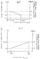
- Figure 2 is a graph showing a relationship between an amperage of a third electric signal, a control point of pressure in a compressor auction chamber, and a detected temperature Tea.
- Figure 3 is a graph showing a relationship between an amperage of twelfth electric signal, the control point of pressure in a compressor suction chamber, and a thermal gradient αn.
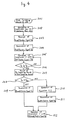
- Figure 4 is a flow chart illustrating an operational manner in an initial operation stage of the automotive air conditioning system shown in Figure 1.
- Figures 5 illustrates a cool-down characteristic in an initial operation stage of an automotive air conditioning system in a situation where temperature of air immediately downstream an evaporator at a time immediately before an operation of a refrigerant circuit is initiated is equal to or higher than one boundary value. In the drawing, a solid line indicates the cool-down characteristic of the automotive air conditioning system shown in Figure 1, and a dashed line indicates the cool-down characteristic of the automotive air conditioning system in accordance with one prior art embodiment.
- Figures 6 illustrates a cool-down characteristic in an initial operation stage of the automotive air conditioning system in a situation where temperature of air immediately downstream an evaporator at a time immediately before the operation of the refrigerant circuit in initiated is lower than one boundary value. In the drawing, a solid line indicates the cool-down characteristic of the automotive air conditioning system shown in Figure 1, and a dashed line indicates the cool-down characteristic of the automotive air conditioning system in accordance with one prior art embodiment.
- With reference to Figure 1 illustrating a block diagram of an automotive air conditioning system in accordance with one embodiment of the present invention, the automotive air conditioning system includes
refrigerant circuit 10 andcontrol apparatus 20 which controls an operation of the automotive air conditioning system.Refrigerant circuit 10 includesrefrigerant compressor 11 with an externally controlled variable capacity control mechanism (not shown),condenser 12,expansion device 13 and evaporator 14 these which are connected in series. Electromagnetic clutch 111 is fixedly mounted oncompressor 11, and intermittently transmits the power derived from an external power source, such as anengine 15 of an automobile to a drive shaft of thecompressor 10 in order to intermittently operate thecompressor 10.Refrigerant circuit 10 further includescondenser fan 121 which is associated withcondenser 12 so as to pass the air through an exterior surface ofcondenser 12 by virtue of operation thereof, andevaporator fan 141 which is associated with evaporator 14 so as to pass the air through an exterior surface of evaporator 14 by virtue of operation thereof.Condenser fan 121 andevaporator fan 141 are operated by receiving an electric power from DC battery 16 installed in an engine compartment of the automobile. -
Control apparatus 20 includesthermosensor 17, primary initialvalue generating device 21,fist comparing device 23, boundaryvalue generating device 24,second comparing device 25, setvalue generating device 26a, subtracter 26b,first operation device 28,second operation device 26c, secondary initialvalue generating device 29,second switching device 27, and amplifier 30 theses which are described in detail below. -
Thermosensor 17 is associated with evaporator 14, of which an outlet is connected to a suction chamber ofcompressor 11, so as to detect temperature Te of the air immediately downstream evaporator 14 at a predetermined very short time interval ΔT, and generates first electric signal S1 representing a detected temperature Te.Thermosensor 17 further detects temperature Tea of the air immediately downstream evaporator 14 at a time immediately before the operation ofcompressor 11, i.e., the operation of therefrigerant circuit 10 is initiated, and generates second electric signal S2 which represents the detected temperature Tea of the air immediately downstream evaporator 14 at a time immediately before the operation of refrigerant circuit is initiated.Thermosensor 17 is connected to a primary initialvalue generating device 21 so as to send second electric signal S2 to primary initialvalue generating device 21. Primary initialvalue generating device 21 is further connected tofirst switching device 22 which is turned on and off so as to initiate and terminate the operation of the automotive air conditioning system. - When the air in a passenger compartment of the automobile is demanded to be cooled, the
first switching device 21 is turned on. As thefirst switching device 21 is turned on, an operation ofevaporator fan 141 andcondenser fan 121 is initiated, and concurrently, an operation ofcontrol apparatus 20 is initiated so thatsecond switching device 27 operates to connect a primary initialvalue generating device 21 to amplifier 30 through first terminal 27a thereof. After this, an electromagnetic coil (not shown ) of electromagnetic clutch 111 is energized so that an operation ofcompressor 11 is initiated. Whencompressor 11 operates, a condensation of the compressed gaseous refrigerant atcondenser 12 with heat exchanging, an expansion of the condensed refrigerant atexpansion device 13, and an evaporation of the expanded refrigerant at evaporator 14 with heat exchanging are successively carried out. Thereafter, the vaporized refrigerant in evaporator 14 returns tocompressor 11. As long ascompressor 11 operates, the above-mentioned successive operational manners are repeated. - According to the initiation of the operation of
control apparatus 20, primary initialvalue generating device 21 processes second electric signal S2 sent fromthermosensor 17 to generate third electric signal S3 of which amperage Ia varies in response to changes in the detected temperature Tea. A manner of generation of third electric signal S3 at primary controlvalue generating device 21 is described in detail below. - With reference to Figure 2, when the detected temperature Tea is equal to or lower than a predetermined first boundary value T1, e.g., 15 °C, amperage Ia of third electric signal S3 is maintained at a first constant value Ic1 which intends to adjust a control point of pressure in a compressor suction chamber at 2.5 kg/cm² G. When the detected temperature Tea is equal to or higher than a predetermined second boundary value T2, e.g., 30 °C which is higher than the predetermined first boundary value T1, amperage Ia of third electric signal S3 is maintained at a second constant value Ic2 which intends to adjust the control point of pressure in the compressor suction chamber at 1.0 kg/cm² G. Furthermore, when the detected temperature Tea is higher than the predetermined first boundary value T1 but is lower the predetermined second boundary value T2, amperage Ia of third electric signal S3 varies in a range between the first constant values Ic1 which intends to adjust the control point of pressure in a compressor suction chamber at 2.5 kg/cm² G and a third constant value Ic3 which intends to adjust the control point of pressure in the compressor suction chamber at 1.7 kg/cm² G.
-
First comparing device 23 is connected tothermosensor 17 so as to receive second electric signal S2 fromthermosensor 17.First comparing device 23 is further connected to a boundaryvalue generating device 24 in which fourth electric signal S4 representing the predetermined second boundary value T2 is generated. First comparingdevice 23 processes second electric signal S2 sent fromthermosensor 17 and fourth electric signal S4 sent from boundaryvalue generating device 24 so as to compare whether the detected temperature Tea is equal to or higher than the predetermined second boundary value T2. - In this comparing process, if the detected temperature Tea is equal to or higher than the predetermined second boundary value T2,
first comparing device 23 generates a fifth electric signal S5 representing the comparing result in which the detected temperature Tea is equal to or higher than the predetermined second boundary value T2. On the other hand, if the detected temperature Tea is lower than the predetermined second boundary value T2,first comparing device 23 generates a sixth electric signal S6 representing the comparing result in which the detected temperature Tea is lower than the predetermined second boundary value T2. -
Second comparing device 25 is connected tothermosensor 17 so as te receive first electric signal S1 representing the detected temperature Te.Second comparing device 25 is further connected to a setvalue generating device 26a in which a seventh electric signal S7 representing a third boundary value T3 which is higher than a set temperature Tset of the air immediately downstream evaporator 14 by a predetermined slight amount of value Δ Tset is generated. Usually, the third boundary value T3 is in a range between the predetermined first and second boundary values T1 and T2.Second comparing device 25 processes first electric signal C1 sent fromthermosensor 17 and the seventh electric signal S7 sent from the setvalue generating device 26a so as to compare whether the detected temperature Te is higher than the third boundary value T3. - In this comparing process, if the detected temperature Te is higher than the third boundary value T3,
second comparing device 25 generates an eighth electric signal S8 representing the comparing result in which the detected temperature Te is higher than the third boundary value T3. On the other hand, if the detected temperature Te is equal to or lower than the third boundary value T3,second comparing device 25 generates an ninth electric signal S9 representing the comparing result in which the detected temperature Te is equal to or lower than the third boundary value T3. -
First operation device 28 is connected tothermosensor 17 so as to receive the first electric signal S1 representing the detected temperature Te fromthermosensor 17.First operation device 28 processes the first electric signal S1 so as to carry out an operation of the following equation.

In equation (1), the appended symbols (n) and (n-m) indicate the ordinal number of the detected temperature Te. α(n) is a thermal gradient of the detected temperature Te(n) with respect to a predetermined short time period βt in a time immediately before the detected temperature Te(n) reaches to the third boundary value T3 from a higher value side of the third boundary value T3. In the term Te(n-m), m is a quotient of βt/ΔT, but is a natural number because that βt is predetermined to be a multiple of ΔT. -
First operation device 28 generates a tenth electric signal S10 representing the thermal gradient α(n) and is connected to a secondary initialvalue generating device 29 so as to output the tenth electric signal S10 to secondary initialvalue generating device 29. Secondary initialvalue generating device 29 is further connected to primary initialvalue generating device 21 so as to receive third electric signal S3 from primary initialvalue generating device 21. Secondary initialvalue generating device 29 is still further connected tofirst comparing device 23 so as to receive fifth and sixth electric signals S5 and S6 from thefirst comparing device 23. Secondary initialvalue generating device 29 processes fifth and sixth electric signals S5 and S6 sent from first comparingdevice 23, third electric signal S3 sent form primary initialvalue generating device 21, and tenth electric signal S10 sent fromfirst operation device 28. - In this processing process, when secondary initial
value generating device 29 receives the sixth electric signal S6 representing the comparing result in which the detected temperature Tea is lower than the predetermined second boundary value T2, secondary initialvalue generating device 29 generates an eleventh electric signal S11 which is identical to the third electric signal S3 having amperage Ia which varies in response to changes in the detected temperature Tea. On the other hand, when secondary initialvalue generating device 29 receives the fifth electric signal S5 representing the comparing result in which the detected temperature Tea is equal to or higher than the predetermined second boundary value T2, secondary controlvalue generating device 29 generates a twelfth electric signal S12 of which amperage Ib varies in response to changes in the thermal gradient α(n). A manner of generation of twelfth electric signal S12 at secondary initialvalue generating device 29 is described in detail below.
with reference to Figure 3, when the thermal gradient α(n) is equal to or smaller than a predetermined first boundary value αa, e.g., 0.01°c/sec., amperage Ib of the twelfth electric signal S12 is maintained at a fourth constant value Ic4 which intends to adjust the control point of pressure in the compressor suction chamber pressure at 1.5 kg/cm² G. When the thermal gradient α(n) is equal to or greater than a predetermined second boundary value αb e.g., 0.1°c/sec. which is greater than the predetermined first boundary value αa, amperage Ib of twelfth electric signal S12 is maintained at a fifth constant value Ic5 which is equal to the first constant value Ic1 shown in Figure 2 and therefore, intends to control the control point of pressure in the compressor suction chamber pressure at 2.5 kg/cm² G. Furthermore, when the thermal gradient α(n) is greater than the predetermined first value αa but is smaller than the predetermined second value αb, amperage Ib of twelfth electric signal S12 varies in a range between the fourth and fifth constant values Ic4 and Ic5 so that the control point of pressure in the compressor suction chamber pressure is intended to be varied within a range between 2.5 kg/cm² G and 1.5 kg/cm² G. Secondary initial value generating device 29 is furthermore connected to second operation device 26c so as to send the eleventh and twelfth electric signals S11 and S12 to second operation device 26c. - The set
value generating device 26a further generates a thirteenth electric signal S13 which represents the set temperature Tset of the air immediately downstream evaporator 14. The setvalue generating device 26a is further connected to subtracter 26b so as to send the thirteenth electric signal S13 to subtracter 26b therefrom. Subtracter 26b is further connected to thermosensor 17 so as to receive the first electric signal S1 representing the detected temperature Te. Subtracter 26b processes the thirteenth electric signal S13 sent from the setvalue generating device 26a and first electric signal S1 sent fromthermosensor 17 so as to subtract the detected temperature Te from the set temperature Tset. This subtraction is shown by the following equation.

The subtracter 26b generates a fourteenth electric signal S14 representing ΔTv and is connected tosecond operation device 26c so as to send the fourteenth electric signal S14 tosecond operation device 26c. -
Second operation device 26c processes the eleventh and twelfth electric signals S11 and S12 sent from secondary initialvalue generating device 29, and fourteenth electric signal S14 sent from subtracter 26b so as to carry out the operation of the following equation.

In equations (3), Kp is a factor of proportionality. Appended symbols (ℓ) or (ℓ-l) indicate the ordinal number of the values processed in thesecond operation device 26c. - When
second operation device 26c receives the eleventh electric signal S11 while the appended symbol (ℓ) is 1, the term I(ℓ-1) becomes Ia. On the other hand, whensecond operation device 26a receives the twelfth electric signal S12 while the appended symbol (ℓ) is 1, the term I(ℓ-l) beams Ib.Second operation device 26a generates a fifteenth electric signal S15 having various amperages I(ℓ). -
Second switching device 27 receives the eighth and ninth electric signals S8 and S9 sent from second comparingdevice 25. Whensecond switching device 27 receives ninth electric signal S9, that is, when the detected temperature Te is equal to or lower than the third boundary value T3,second switching device 27 operates to connectsecond operation device 26c toamplifier 30 through second terminal 27b ofsecond switching device 27 so that amperage I(ℓ) of the fifteenth electric signal S15 is amplified to be amperage GI(I(ℓ)) byamplifier 30. In the formula GI(I(ℓ)), GI is the gain given by virtue of operation ofamplifier 30. The electric current having amplified amperage GI(I(ℓ)) is supplied to a solenoid (not shown) of the externally controlled variable capacity control mechanism of the compressor. On the other hand, whensecond switching device 27 receives eighth electric signal S8, that is, when the detected temperature Te is higher than the third boundary value T3, the connection between primary initialvalue generating device 21 andamplifier 30 is maintained so that amperage Ia of the third electric signal S3 is amplified to be amperage GI(Ia) byamplifier 30. The electric current having amplified amperage GI(Ia) is supplied to the solenoid (not shown) of the externally controlled variable capacity control mechanism of the compressor. - In this embodiment, when the amplified amperage of the electric current supplied to the solenoid of the externally controlled variable capacity control mechanism of the compressor increases, the control point of pressure in the compressor suction chamber is shifted to a greater value side thereof. In reverse, when the amplified amperage of the electric current supplied to the solenoid of the externally controlled variable capacity control mechanism of the compressor decreases, the control point of pressure in the compressor suction chamber is shifted to a smaller value side thereof.
- Furthermore, set
value generating device 26a, subtracter 26b andsecond operation device 26c form acontrol device 26 which carries out a proportional control action. - An operational manner of the automotive air conditioning system in accordance with one embodiment of the present invention is described below. With reference to Figure 4 in addition to Figure 1, initially, when the air of the passenger compartment of the automobile is demanded to be cooled, the
first switching device 22 is turned on so as to initiate the operation of the automotive air conditioning system instep 201. When thefirst switching device 22 is turned on,step 201 proceeds to step 202. Instep 202, the operation ofcondenser fan 121 andevaporator fan 141 is initiated, and concurrently, the operation ofcontrol apparatus 20 is initiated so thatsecond switching device 27 operates to connect primary initialvalue generating device 21 toamplifier 30 through first terminal 27a thereof. - When primary initial
value generating device 21 is connected toamplifier 30,step 202 proceeds to step 203. Instep 203, the second electric signal S2 representing the detected temperature Tea is sent to primary initialvalue generating device 21 and first comparingdevice 23 fromthermosensor 17. When second electric signal S2 is sent to primary initialvalue generating device 21 and first comparingdevice 23,step 203 proceeds to step 204. Instep 204, primary initialvalue generating device 21 processes the second electric signal S2 so as to generate third electric signal S3 having various amperages Ia shown in Figure 2. When third electric signal S3 is generated in primary initialvalue generating device 21,step 204 proceeds to step 205. - In
step 205, the operation ofcompressor 11 is initiated by receiving the power from the engine of the automobile through electromagnetic clutch 111 while the third electric signal S3 is sent from primary initialvalue generating device 21 toamplifier 30 through first terminal 27a ofsecond switching device 27 so that the electric current having the amplified amperage GI(Ia) is supplied to the solenoid of the externally controlled capacity control mechanism of the compressor so as to adjust the control point of pressure in the compressor suction chamber to be maintained at one certain value. Furthermore, if the detected temperature Tea is equal to or higher than the predetermined second boundary value T2, amperage Ia of third electric signal S3 is maintained at the second constant value Ic2 so that the control point of pressure in the compressor suction chamber is adjusted to be maintained at 1.0 kg/cm² G. On the other hand, if the detected temperature Tea is lower than the predetermined second boundary value T2, amperage Ia of third electric signal S3 is maintained at one certain value which is greater than the third constant value Ic3 so that the control point of pressure in the compressor suction chamber is adjusted to be maintained at one certain value which is greater than 1.7 kg/cm² G. - After the duration of operation of the
compressor 11 instep 205, step 205 proceeds to step 206. Instep 206, the second comparingdevice 25 compares whether the detected temperature Te is higher than the third boundary value T3. If the detected temperature Te is higher than the third boundary value T3, step 206 returns to step 205. On the other hand, if the detected temperature Te is equal to or lower than the third boundary value T3, step 206 proceeds to step 207. Instep 207,second switching device 27 operates to connectsecond operation device 26c toamplifier 30 through second terminal 27a thereof, and concurrently, the comparing result of first comparingdevice 23 is recalled. - When
second operation device 26c is connected toamplifier 30, and concurrently, the comparing result of first comparingdevice 23 is recalled, step 207 proceeds to step 208. Instep 208, if the recalled comparing result of first comparingdevice 23 shows that the detected temperature Tea is lower than the predetermined second boundary value T2, step 208 proceeds to step 209. Instep 209, eleventh electric signal S11 which is identical to third electric signal S3 is sent tosecond operation device 26c from secondary initialvalue generating device 29. When the eleventh electric signal S11 is sent tosecond operation device 26c,step 209 proceeds to step 212. - On the other hand, if the recalled comparing result of first comparing
device 23 shows that the detected temperature Tea is equal to or higher than the predetermined second boundary value T2, step 208 proceeds to step 210. Instep 210, the operation of equation (1) is carried out infirst operation device 28 so as to generate tenth electric signal S10. When the tenth electric signal S10 is generated infirst operation device 28,step 210 proceeds to step 211. Instep 211, the tenth electric signal S10 is processed in secondary initialvalue generating device 29 so as to generate twelfth electric signal S12. Then, the twelfth electric signal S12 is sent tosecond operation device 26c from secondary initialvalue generating device 29. When the twelfth electric signal S12 is sent tosecond operation device 26c from secondary initialvalue generating device 29,step 211 proceeds to step 212. - In
step 212, the operation of equation (3) is carried out insecond operation device 26c so as to generate fifteenth electric signal S15 having various amperage I(l), and fifteenth electric signal S15 is sent toamplifier 30 through second terminal 27b ofsecond switching device 27 to be amplified its amperage. Then, the electric current having amplified amperage GI(I(ℓ)) is supplied to the solenoid of the externally controlled variable capacity control mechanism of thecompressor 11 so as to adjust the control point of pressure in the compressor suction chamber at various values so that the temperature Te is converged at the set temperature Tset. Step 212 continuously goes on until the operation of the automotive air conditioning system is terminated. - Figures 5 illustrates a cool-down characteristic in the initial operation stage of the automotive air conditioning system in a situation where the detected temperature Te is equal to or higher the predetermined second boundary value T2. More specifically, in Figure 5, the cool-down characteristic of the automotive air conditioning system in accordance with one embodiment of the present is indicated by a solid line.
- With reference to Figure 5, from a time t0 when the operation of
refrigerant circuit 10 is initiated to a time t1 when the temperature Te drops to the third boundary value T3, the control point of pressure in the compressor suction chamber is adjusted by the third electric signal S3 of which amperage Ia is second constant value Ic2 so as to maintain at 1.0 kg/cm²G. Therefore, the temperature Te quickly drops to the third boundary value T3 by the time t1. - Once the temperature Te drops to the third boundary value T3 at the time t1, the control point of pressure in the compressor suction chamber is adjusted by the proportional control action which is initialized by twelfth electric signal S12 of which amperage Ib is a relatively larger value. Accordingly, in the initial operation stage of the automotive air conditioning system, the temperature Te of the air immediately downstream evaporator 14 quickly drops without overshooting from the set temperature Tset while is quickly and effectively converged at the set temperature Tset.
- Therefore, the passenger compartment of the automobile can be more adequately air conditioned in the initial operation stage of the automotive air conditioning system.
- Figure 6 illustrates a cool-down characteristic of the automotive air conditioning system in accordance with one embodiment of the present invention in a situation where temperature Tea is lower than the predetermined second boundary value T2. More specifically, in Figure 6, the cool-down characteristic of the automotive air conditioning system in accordance with one embodiment of the present is indicated by a solid line.
- With reference to Figure 6, from the time t0 when the operation of
refrigerant circuit 10 is initiated to the time t1 when the temperature Te drops to the third boundary value T3, the control point of pressure in the compressor suction chamber is adjusted by the third electric signal S3 of which amperage Ia is relatively larger value so as to maintain at a relatively larger value. Therefore, the temperature Te gently drops to the third boundary value T3 by the time t1. - Once the temperature Te drops to the third boundary value T3 at the time t1, the control point of pressure in the compressor suction chamber is adjusted by the proportional control action which is initialized by eleventh electric signal S11 which is identical to the third electric signal S3. Accordingly, in the initial operation stage of the automotive air conditioning system, the temperature Te of the air immediately downstream evaporator 14 gently drops without overshooting from the set temperature Tset while is quickly and effectively converged at the set temperature Tset.
- Therefore, the passenger compartment of the automobile can be more adequately air conditioned in the initial operation stage of the automotive air conditioning system.
Claims (5)
- In an automotive air conditioning system including,
a refrigerant circuit having a refrigerant compressor with an externally controlled variable capacity control mechanism and an evaporator connected to a suction chamber of said refrigerant compressor;
moving means for moving air through an exterior surface of said evaporator;
and a control mechanism for controlling an operation thereof;
said control mechanism including,
sensing means for sensing temperature of air immediately downstream said evaporator,
a first determining means for determining a first value of a control point of pressure in said suction chamber of said compressor according to the temperature of air immediately downstream the evaporator at a time immediately before the operation of said refrigerant circuit is initiated,
comparing means for comparing the temperature of air immediately downstream the evaporator during the operation of said refrigerant circuit is higher than one certain value which is higher than a set value,
a second determining means for determining a second value of the control point of pressure in said suction chamber of said compressor, according to a thermal gradient with respect to a time in a situation where the temperature of air immediately downstream the evaporator immediately before reaches said one certain value from a higher value side thereof,
carrying out means for carrying out operation of a feedback control action,
changing means for changing a first situation in which the control point of pressure in said suction chamber of said compressor is adjusted to be maintained at said first value to a second situation in which the control point of pressure in said suction chamber of said compressor is adjusted to be varied by a result of operation of said feedback control action when the temperature of air immediately downstream the evaporator during the operation of said refrigerant circuit is equal to or lower than the one certain value. - The automotive air conditioning system of claim 1 wherein said feedback control action is a proportional control action which includes a value obtained by subtracting the temperature of air immediately downstream the evaporator during the operation of said refrigerant circuit from the set temperature.
- The automotive air conditioning system of claim 2 further including another comparing means for comparing the temperature of air immediately downstream the evaporator at the time immediately before the operation of said refrigerant circuit is initiated is equal to or higher than one predetermined boundary value.
- The automotive air conditioning system of claim 3 wherein said proportional control action is initialized by said first value when the temperature of air immediately downstream the evaporator at the time immediately before the operation of said refrigerant circuit is initiated is lower than said one predetermined boundary value.
- The automotive air conditioning system of claim 3 wherein said proportional control action is initialized by said second value when the temperature of air immediately downstream the evaporator at the time immediately before the operation of said refrigerant circuit is initiated is equal to or higher than said one predetermined boundary value.
Applications Claiming Priority (3)
| Application Number | Priority Date | Filing Date | Title |
|---|---|---|---|
| JP106692 | 1992-01-07 | ||
| JP1066/92 | 1992-01-07 | ||
| US08/002,019 US5315841A (en) | 1992-01-07 | 1993-01-08 | Control apparatus for use in automotive air conditioning system |
Publications (2)
| Publication Number | Publication Date |
|---|---|
| EP0551008A1 true EP0551008A1 (en) | 1993-07-14 |
| EP0551008B1 EP0551008B1 (en) | 1996-03-06 |
Family
ID=26334228
Family Applications (1)
| Application Number | Title | Priority Date | Filing Date |
|---|---|---|---|
| EP92311824A Expired - Lifetime EP0551008B1 (en) | 1992-01-07 | 1992-12-24 | Control apparatus for use in automotive air conditioning system |
Country Status (2)
| Country | Link |
|---|---|
| US (1) | US5315841A (en) |
| EP (1) | EP0551008B1 (en) |
Cited By (4)
| Publication number | Priority date | Publication date | Assignee | Title |
|---|---|---|---|---|
| EP1004463A1 (en) * | 1998-11-23 | 2000-05-31 | Delphi Technologies, Inc. | Dual mode control of a variable displacement refrigerant compressor of an automotive air conditioning system |
| EP1004828A3 (en) * | 1998-11-23 | 2000-11-15 | Delphi Technologies, Inc. | Method for regulating the cooling performance of an air conditioning system |
| EP1772298A2 (en) | 2005-10-07 | 2007-04-11 | Halla Climate Control Corporation | Method for controlling variable capacity compressor of air conditioner |
| EP1717073A4 (en) * | 2004-02-16 | 2008-05-21 | Sanden Corp | Vehicle air conditioner |
Families Citing this family (3)
| Publication number | Priority date | Publication date | Assignee | Title |
|---|---|---|---|---|
| JP3290031B2 (en) * | 1994-07-06 | 2002-06-10 | サンデン株式会社 | Vehicle air conditioner |
| US6016966A (en) * | 1996-08-26 | 2000-01-25 | Sanden Corporation | Air conditioning system for automotive vehicles |
| US6663358B2 (en) | 2001-06-11 | 2003-12-16 | Bristol Compressors, Inc. | Compressors for providing automatic capacity modulation and heat exchanging system including the same |
Citations (5)
| Publication number | Priority date | Publication date | Assignee | Title |
|---|---|---|---|---|
| EP0275045A2 (en) * | 1987-01-10 | 1988-07-20 | Sanden Corporation | Device for controlling capacity of variable capacity compressor |
| DE3829096A1 (en) * | 1987-08-28 | 1989-03-16 | Toyoda Automatic Loom Works | DEVICE FOR CONTROLLING FLOW RATE ADJUSTMENT DEVICES OF A REFRIGERANT COMPRESSOR |
| US4893480A (en) * | 1987-03-13 | 1990-01-16 | Nippondenso Co., Ltd. | Refrigeration cycle control apparatus |
| US4909043A (en) * | 1987-10-26 | 1990-03-20 | Diesel Kiki Co., Ltd. | Air conditioning control system for automotive vehicles |
| US5022234A (en) * | 1990-06-04 | 1991-06-11 | General Motors Corporation | Control method for a variable displacement air conditioning system compressor |
Family Cites Families (2)
| Publication number | Priority date | Publication date | Assignee | Title |
|---|---|---|---|---|
| US4848099A (en) * | 1988-09-14 | 1989-07-18 | Honeywell Inc. | Adaptive refrigerant control algorithm |
| JPH0674010B2 (en) * | 1990-06-04 | 1994-09-21 | 株式会社ゼクセル | Variable capacity compressor controller for vehicle air conditioner |
-
1992
- 1992-12-24 EP EP92311824A patent/EP0551008B1/en not_active Expired - Lifetime
-
1993
- 1993-01-08 US US08/002,019 patent/US5315841A/en not_active Expired - Fee Related
Patent Citations (5)
| Publication number | Priority date | Publication date | Assignee | Title |
|---|---|---|---|---|
| EP0275045A2 (en) * | 1987-01-10 | 1988-07-20 | Sanden Corporation | Device for controlling capacity of variable capacity compressor |
| US4893480A (en) * | 1987-03-13 | 1990-01-16 | Nippondenso Co., Ltd. | Refrigeration cycle control apparatus |
| DE3829096A1 (en) * | 1987-08-28 | 1989-03-16 | Toyoda Automatic Loom Works | DEVICE FOR CONTROLLING FLOW RATE ADJUSTMENT DEVICES OF A REFRIGERANT COMPRESSOR |
| US4909043A (en) * | 1987-10-26 | 1990-03-20 | Diesel Kiki Co., Ltd. | Air conditioning control system for automotive vehicles |
| US5022234A (en) * | 1990-06-04 | 1991-06-11 | General Motors Corporation | Control method for a variable displacement air conditioning system compressor |
Cited By (5)
| Publication number | Priority date | Publication date | Assignee | Title |
|---|---|---|---|---|
| EP1004463A1 (en) * | 1998-11-23 | 2000-05-31 | Delphi Technologies, Inc. | Dual mode control of a variable displacement refrigerant compressor of an automotive air conditioning system |
| EP1004828A3 (en) * | 1998-11-23 | 2000-11-15 | Delphi Technologies, Inc. | Method for regulating the cooling performance of an air conditioning system |
| EP1717073A4 (en) * | 2004-02-16 | 2008-05-21 | Sanden Corp | Vehicle air conditioner |
| EP1772298A2 (en) | 2005-10-07 | 2007-04-11 | Halla Climate Control Corporation | Method for controlling variable capacity compressor of air conditioner |
| EP1772298A3 (en) * | 2005-10-07 | 2009-02-25 | Halla Climate Control Corporation | Method for controlling variable capacity compressor of air conditioner |
Also Published As
| Publication number | Publication date |
|---|---|
| US5315841A (en) | 1994-05-31 |
| EP0551008B1 (en) | 1996-03-06 |
Similar Documents
| Publication | Publication Date | Title |
|---|---|---|
| EP0007775B2 (en) | Electric control method and apparatus for automobile air conditioning system | |
| EP0026612B1 (en) | Electrical control method and system for an automobile air conditioner | |
| US5669226A (en) | Air conditioning apparatus for a vehicle | |
| EP0551008B1 (en) | Control apparatus for use in automotive air conditioning system | |
| EP0032735B1 (en) | Method and system for controlling a vehicle-mounted air conditioner | |
| EP0531089B1 (en) | Automotive air conditioning system having refrigerant compressor with externally controlled variable displacement mechanism | |
| EP0749856A2 (en) | Air conditioning apparatus | |
| JP2003335127A (en) | Vehicle electrical equipment control device | |
| JP2001248881A (en) | Air conditioner | |
| EP0621147B1 (en) | Control apparatus for use in automotive air conditioning system | |
| JP2011173491A (en) | Air conditioner for vehicle | |
| EP0228813B1 (en) | Air conditioner for automobiles | |
| EP0051831A1 (en) | Air-conditioning method and system for an automotive vehicle | |
| EP1897712A2 (en) | Air-conditioning system for vehicle | |
| EP1308327B1 (en) | Energy efficient control method for a manually regulated vehicle heating and air conditioning system | |
| EP0557747B1 (en) | Measuring evaporator load in an automotive air conditioning system for compressor clutch control | |
| US6820438B2 (en) | Vehicle air conditioner | |
| JP3387949B2 (en) | Air conditioning system | |
| JPH0558151A (en) | Air-conditioning device for vehicle | |
| EP1717075A1 (en) | Air conditioner | |
| JP3387973B2 (en) | Vehicle air conditioner | |
| EP1717073A1 (en) | Vehicle air conditioner | |
| US20060278385A1 (en) | Air conditioning system and method for regulating the heating capacity thereof | |
| JPH03291463A (en) | Superheat degree-controlling device for cooling-cycle | |
| EP0085245B1 (en) | A capacity control device for a compressor in a refrigerating system |
Legal Events
| Date | Code | Title | Description |
|---|---|---|---|
| PUAI | Public reference made under article 153(3) epc to a published international application that has entered the european phase |
Free format text: ORIGINAL CODE: 0009012 |
|
| AK | Designated contracting states |
Kind code of ref document: A1 Designated state(s): DE FR GB IT SE |
|
| 17P | Request for examination filed |
Effective date: 19940111 |
|
| 17Q | First examination report despatched |
Effective date: 19941201 |
|
| GRAA | (expected) grant |
Free format text: ORIGINAL CODE: 0009210 |
|
| AK | Designated contracting states |
Kind code of ref document: B1 Designated state(s): DE FR GB IT SE |
|
| ET | Fr: translation filed | ||
| REF | Corresponds to: |
Ref document number: 69208855 Country of ref document: DE Date of ref document: 19960411 |
|
| ITF | It: translation for a ep patent filed | ||
| PLBE | No opposition filed within time limit |
Free format text: ORIGINAL CODE: 0009261 |
|
| STAA | Information on the status of an ep patent application or granted ep patent |
Free format text: STATUS: NO OPPOSITION FILED WITHIN TIME LIMIT |
|
| 26N | No opposition filed | ||
| PGFP | Annual fee paid to national office [announced via postgrant information from national office to epo] |
Ref country code: SE Payment date: 20001206 Year of fee payment: 9 |
|
| PGFP | Annual fee paid to national office [announced via postgrant information from national office to epo] |
Ref country code: FR Payment date: 20011212 Year of fee payment: 10 |
|
| PG25 | Lapsed in a contracting state [announced via postgrant information from national office to epo] |
Ref country code: SE Free format text: LAPSE BECAUSE OF NON-PAYMENT OF DUE FEES Effective date: 20011225 |
|
| REG | Reference to a national code |
Ref country code: GB Ref legal event code: IF02 |
|
| PGFP | Annual fee paid to national office [announced via postgrant information from national office to epo] |
Ref country code: DE Payment date: 20020109 Year of fee payment: 10 |
|
| EUG | Se: european patent has lapsed |
Ref document number: 92311824.4 |
|
| PGFP | Annual fee paid to national office [announced via postgrant information from national office to epo] |
Ref country code: GB Payment date: 20021218 Year of fee payment: 11 |
|
| PG25 | Lapsed in a contracting state [announced via postgrant information from national office to epo] |
Ref country code: DE Free format text: LAPSE BECAUSE OF NON-PAYMENT OF DUE FEES Effective date: 20030701 |
|
| PG25 | Lapsed in a contracting state [announced via postgrant information from national office to epo] |
Ref country code: FR Free format text: LAPSE BECAUSE OF NON-PAYMENT OF DUE FEES Effective date: 20030901 |
|
| REG | Reference to a national code |
Ref country code: FR Ref legal event code: ST |
|
| PG25 | Lapsed in a contracting state [announced via postgrant information from national office to epo] |
Ref country code: GB Free format text: LAPSE BECAUSE OF NON-PAYMENT OF DUE FEES Effective date: 20031224 |
|
| GBPC | Gb: european patent ceased through non-payment of renewal fee |
Effective date: 20031224 |
|
| PG25 | Lapsed in a contracting state [announced via postgrant information from national office to epo] |
Ref country code: IT Free format text: LAPSE BECAUSE OF NON-PAYMENT OF DUE FEES;WARNING: LAPSES OF ITALIAN PATENTS WITH EFFECTIVE DATE BEFORE 2007 MAY HAVE OCCURRED AT ANY TIME BEFORE 2007. THE CORRECT EFFECTIVE DATE MAY BE DIFFERENT FROM THE ONE RECORDED. Effective date: 20051224 |