EP0550800A2 - Method for manufacturing molded products using an extruder and a mold, and equipment to be used therewith - Google Patents
Method for manufacturing molded products using an extruder and a mold, and equipment to be used therewith Download PDFInfo
- Publication number
- EP0550800A2 EP0550800A2 EP19920117157 EP92117157A EP0550800A2 EP 0550800 A2 EP0550800 A2 EP 0550800A2 EP 19920117157 EP19920117157 EP 19920117157 EP 92117157 A EP92117157 A EP 92117157A EP 0550800 A2 EP0550800 A2 EP 0550800A2
- Authority
- EP
- European Patent Office
- Prior art keywords
- tile
- roof
- extruder
- plastic
- tiles
- Prior art date
- Legal status (The legal status is an assumption and is not a legal conclusion. Google has not performed a legal analysis and makes no representation as to the accuracy of the status listed.)
- Granted
Links
Images


Classifications
-
- B—PERFORMING OPERATIONS; TRANSPORTING
- B29—WORKING OF PLASTICS; WORKING OF SUBSTANCES IN A PLASTIC STATE IN GENERAL
- B29B—PREPARATION OR PRETREATMENT OF THE MATERIAL TO BE SHAPED; MAKING GRANULES OR PREFORMS; RECOVERY OF PLASTICS OR OTHER CONSTITUENTS OF WASTE MATERIAL CONTAINING PLASTICS
- B29B17/00—Recovery of plastics or other constituents of waste material containing plastics
- B29B17/04—Disintegrating plastics, e.g. by milling
- B29B17/0412—Disintegrating plastics, e.g. by milling to large particles, e.g. beads, granules, flakes, slices
-
- E—FIXED CONSTRUCTIONS
- E04—BUILDING
- E04D—ROOF COVERINGS; SKY-LIGHTS; GUTTERS; ROOF-WORKING TOOLS
- E04D1/00—Roof covering by making use of tiles, slates, shingles, or other small roofing elements
- E04D1/02—Grooved or vaulted roofing elements
- E04D1/08—Grooved or vaulted roofing elements of plastics; of asphalt; of fibrous materials
-
- B—PERFORMING OPERATIONS; TRANSPORTING
- B29—WORKING OF PLASTICS; WORKING OF SUBSTANCES IN A PLASTIC STATE IN GENERAL
- B29C—SHAPING OR JOINING OF PLASTICS; SHAPING OF MATERIAL IN A PLASTIC STATE, NOT OTHERWISE PROVIDED FOR; AFTER-TREATMENT OF THE SHAPED PRODUCTS, e.g. REPAIRING
- B29C48/00—Extrusion moulding, i.e. expressing the moulding material through a die or nozzle which imparts the desired form; Apparatus therefor
- B29C48/022—Extrusion moulding, i.e. expressing the moulding material through a die or nozzle which imparts the desired form; Apparatus therefor characterised by the choice of material
-
- B—PERFORMING OPERATIONS; TRANSPORTING
- B29—WORKING OF PLASTICS; WORKING OF SUBSTANCES IN A PLASTIC STATE IN GENERAL
- B29C—SHAPING OR JOINING OF PLASTICS; SHAPING OF MATERIAL IN A PLASTIC STATE, NOT OTHERWISE PROVIDED FOR; AFTER-TREATMENT OF THE SHAPED PRODUCTS, e.g. REPAIRING
- B29C48/00—Extrusion moulding, i.e. expressing the moulding material through a die or nozzle which imparts the desired form; Apparatus therefor
- B29C48/03—Extrusion moulding, i.e. expressing the moulding material through a die or nozzle which imparts the desired form; Apparatus therefor characterised by the shape of the extruded material at extrusion
- B29C48/12—Articles with an irregular circumference when viewed in cross-section, e.g. window profiles
-
- E—FIXED CONSTRUCTIONS
- E04—BUILDING
- E04C—STRUCTURAL ELEMENTS; BUILDING MATERIALS
- E04C3/00—Structural elongated elements designed for load-supporting
- E04C3/02—Joists; Girders, trusses, or trusslike structures, e.g. prefabricated; Lintels; Transoms; Braces
- E04C3/29—Joists; Girders, trusses, or trusslike structures, e.g. prefabricated; Lintels; Transoms; Braces built-up from parts of different material, i.e. composite structures
-
- E—FIXED CONSTRUCTIONS
- E04—BUILDING
- E04D—ROOF COVERINGS; SKY-LIGHTS; GUTTERS; ROOF-WORKING TOOLS
- E04D1/00—Roof covering by making use of tiles, slates, shingles, or other small roofing elements
- E04D1/29—Means for connecting or fastening adjacent roofing elements
- E04D1/2907—Means for connecting or fastening adjacent roofing elements by interfitted sections
- E04D1/2914—Means for connecting or fastening adjacent roofing elements by interfitted sections having fastening means or anchors at juncture of adjacent roofing elements
- E04D1/2916—Means for connecting or fastening adjacent roofing elements by interfitted sections having fastening means or anchors at juncture of adjacent roofing elements the fastening means taking hold directly on adjacent elements of the same row
-
- E—FIXED CONSTRUCTIONS
- E04—BUILDING
- E04D—ROOF COVERINGS; SKY-LIGHTS; GUTTERS; ROOF-WORKING TOOLS
- E04D1/00—Roof covering by making use of tiles, slates, shingles, or other small roofing elements
- E04D1/30—Special roof-covering elements, e.g. ridge tiles, gutter tiles, gable tiles, ventilation tiles
-
- B—PERFORMING OPERATIONS; TRANSPORTING
- B29—WORKING OF PLASTICS; WORKING OF SUBSTANCES IN A PLASTIC STATE IN GENERAL
- B29K—INDEXING SCHEME ASSOCIATED WITH SUBCLASSES B29B, B29C OR B29D, RELATING TO MOULDING MATERIALS OR TO MATERIALS FOR MOULDS, REINFORCEMENTS, FILLERS OR PREFORMED PARTS, e.g. INSERTS
- B29K2105/00—Condition, form or state of moulded material or of the material to be shaped
- B29K2105/06—Condition, form or state of moulded material or of the material to be shaped containing reinforcements, fillers or inserts
- B29K2105/065—Condition, form or state of moulded material or of the material to be shaped containing reinforcements, fillers or inserts containing impurities
-
- B—PERFORMING OPERATIONS; TRANSPORTING
- B29—WORKING OF PLASTICS; WORKING OF SUBSTANCES IN A PLASTIC STATE IN GENERAL
- B29K—INDEXING SCHEME ASSOCIATED WITH SUBCLASSES B29B, B29C OR B29D, RELATING TO MOULDING MATERIALS OR TO MATERIALS FOR MOULDS, REINFORCEMENTS, FILLERS OR PREFORMED PARTS, e.g. INSERTS
- B29K2105/00—Condition, form or state of moulded material or of the material to be shaped
- B29K2105/06—Condition, form or state of moulded material or of the material to be shaped containing reinforcements, fillers or inserts
- B29K2105/16—Fillers
-
- B—PERFORMING OPERATIONS; TRANSPORTING
- B29—WORKING OF PLASTICS; WORKING OF SUBSTANCES IN A PLASTIC STATE IN GENERAL
- B29L—INDEXING SCHEME ASSOCIATED WITH SUBCLASS B29C, RELATING TO PARTICULAR ARTICLES
- B29L2031/00—Other particular articles
- B29L2031/10—Building elements, e.g. bricks, blocks, tiles, panels, posts, beams
- B29L2031/104—Tiles
-
- E—FIXED CONSTRUCTIONS
- E04—BUILDING
- E04D—ROOF COVERINGS; SKY-LIGHTS; GUTTERS; ROOF-WORKING TOOLS
- E04D1/00—Roof covering by making use of tiles, slates, shingles, or other small roofing elements
- E04D1/30—Special roof-covering elements, e.g. ridge tiles, gutter tiles, gable tiles, ventilation tiles
- E04D2001/301—Special roof-covering elements, e.g. ridge tiles, gutter tiles, gable tiles, ventilation tiles at roof edges, e.g. intersections with walls
- E04D2001/302—Gable tiles
-
- E—FIXED CONSTRUCTIONS
- E04—BUILDING
- E04D—ROOF COVERINGS; SKY-LIGHTS; GUTTERS; ROOF-WORKING TOOLS
- E04D1/00—Roof covering by making use of tiles, slates, shingles, or other small roofing elements
- E04D1/30—Special roof-covering elements, e.g. ridge tiles, gutter tiles, gable tiles, ventilation tiles
- E04D2001/301—Special roof-covering elements, e.g. ridge tiles, gutter tiles, gable tiles, ventilation tiles at roof edges, e.g. intersections with walls
- E04D2001/303—Eave tiles
-
- E—FIXED CONSTRUCTIONS
- E04—BUILDING
- E04D—ROOF COVERINGS; SKY-LIGHTS; GUTTERS; ROOF-WORKING TOOLS
- E04D1/00—Roof covering by making use of tiles, slates, shingles, or other small roofing elements
- E04D1/30—Special roof-covering elements, e.g. ridge tiles, gutter tiles, gable tiles, ventilation tiles
- E04D2001/304—Special roof-covering elements, e.g. ridge tiles, gutter tiles, gable tiles, ventilation tiles at roof intersections, e.g. valley tiles, ridge tiles
- E04D2001/305—Ridge or hip tiles
-
- E—FIXED CONSTRUCTIONS
- E04—BUILDING
- E04D—ROOF COVERINGS; SKY-LIGHTS; GUTTERS; ROOF-WORKING TOOLS
- E04D1/00—Roof covering by making use of tiles, slates, shingles, or other small roofing elements
- E04D1/30—Special roof-covering elements, e.g. ridge tiles, gutter tiles, gable tiles, ventilation tiles
- E04D2001/307—Special roof-covering elements, e.g. ridge tiles, gutter tiles, gable tiles, ventilation tiles for passages in the roof surface
-
- E—FIXED CONSTRUCTIONS
- E04—BUILDING
- E04D—ROOF COVERINGS; SKY-LIGHTS; GUTTERS; ROOF-WORKING TOOLS
- E04D1/00—Roof covering by making use of tiles, slates, shingles, or other small roofing elements
- E04D1/30—Special roof-covering elements, e.g. ridge tiles, gutter tiles, gable tiles, ventilation tiles
- E04D2001/309—Ventilation tiles
-
- Y—GENERAL TAGGING OF NEW TECHNOLOGICAL DEVELOPMENTS; GENERAL TAGGING OF CROSS-SECTIONAL TECHNOLOGIES SPANNING OVER SEVERAL SECTIONS OF THE IPC; TECHNICAL SUBJECTS COVERED BY FORMER USPC CROSS-REFERENCE ART COLLECTIONS [XRACs] AND DIGESTS
- Y02—TECHNOLOGIES OR APPLICATIONS FOR MITIGATION OR ADAPTATION AGAINST CLIMATE CHANGE
- Y02W—CLIMATE CHANGE MITIGATION TECHNOLOGIES RELATED TO WASTEWATER TREATMENT OR WASTE MANAGEMENT
- Y02W30/00—Technologies for solid waste management
- Y02W30/50—Reuse, recycling or recovery technologies
- Y02W30/62—Plastics recycling; Rubber recycling
Definitions
- thermoplastic waste is generally known through the article by Tenner, Helmut: “Processing of thermoplastic waste in the melt” in the book “Recycling thermoplastic waste”, publisher: VDI-Gesellschaft Kunststofftechnik, 1979, Düsseldorf, VDI -Publisher, pages 63 to 77.
- the invention is therefore based on the object of proposing a method and an installation for the production of molded parts with which a cheaper production of such molded parts is possible.
- this object is achieved in that a mixture containing unpurified waste plastics, which have thermoplastic components, and fillers are comminuted and then fed to an extruder in a suitable ratio, whereupon the pulpy mass emerging at the head of the extruder is shaped into a mold the molded parts is driven.
- the uncleaned old plastics and fillers can be processed without further processing e.g. B. the separate household waste, which can consist of any plastics such as. B. plastic bags, but also from any composite materials that contain plastic, such as. B. plastic-coated and aluminum-coated or additionally paper-coated liquid containers and other cellulose-containing substances such as paper or cardboard. It can also non-thermoplastic materials and even metal parts such. B.
- metal beverage cans may be included, all of which may occur in the distribution typically occurring in household waste.
- the thermoplastic components melt in the extruder and envelop the non-meltable components, even if they are thermosets, metals or cellulose fibers.
- there is always a component of about 1% PVC in the batch which would initially have been expected to produce and escape toxic chlorine gases during processing in the extruder.
- no chlorine gases escape since these are apparently trapped and enclosed with or before their formation by the plastic parts that have already become mushy or liquid.
- the solution described thus allows the use of low-quality waste, from which a high-quality product with excellent strength properties can be produced.
- the waste plastics are unsorted and with adhering composites, such as. B.
- the fillers can preferably assume a proportion of 50 percent by weight.
- the shredded fillers are all pushed into the interior of the molded part and are not covered with plastic in their entirety but in particles.
- the pulpy plastic also bonds with each other and also connects with the outer plastic skin, in which there are no fillers.
- This outer plastic skin can be more than 1 mm thick. This creates a very solid molded part that absorbs water only to an extremely small extent. Due to the low water absorption capacity, in contrast to other plastic parts, there is no swelling in the water.
- a special type of the method described is that the mushy mass is brought by the shape with the same dimensions and at least approximately the same weight into the shape corresponding to a shape made of clay or clay-containing masses or cast from concrete roof tiles.
- the pressure in the assigned form preferably in size order of 250 bar.
- the roof tiles produced in this way are high-strength and flame-retardant due to their strong pressure.
- Their handling - which is convenient for the responsible craftsman - is almost identical to the well-known roof tiles made of clay or clay-containing masses or made of poured concrete.
- they can be colored as desired and cut very easily on site to adapt to local conditions using hand-held tools without the risk of breakage.
- such roof tiles can be profiled, z. B.
- roof panels or corrugated panels which are each not only suitable for a roof covering.
- Such roof tiles do not have to be handled carefully during transport, but can simply be tipped over at the construction site without the risk of breakage.
- the use of the inferior waste material described at the beginning makes the production of these roof tiles very cheap.
- additives in the course of the process for the production of the molded parts which make the finished products flame-retardant.
- Such an addition can e.g. B. be magnesium hydroxide.
- Appropriate preparations are commercially available, for. B. under the name Magnifin H10 from Martinswerk GmbH in 5010 Bergheim.
- a plant for carrying out the method according to the invention is characterized by at least one comminution device for comminuting the unpurified old plastics and the fillers, which is or are connected by means of transport to an associated extruder, which in turn is connected to a mold for producing the molded parts.
- the system for carrying out the method is therefore very simple.
- the means of transport can be simple conveyor belts.
- a shredding device is sufficient for shredding. If plastics are shredded with composites, the proportion of the composites as filler may already be in a desired amount. If more filler is to be used, it is possible to use e.g. B. Add waste papers in the desired amount. Both the waste paper and the unsorted plastics are then shredded by the same shredding device.
- the shredded products are then z. B. fed to the extruder via simple conveyor belts. It is also possible here that the products coming from the shredding devices are first stored in an intermediate store and then fed to the extruder in a desired ratio via the transport device. It is also possible to first mix the shredded plastic parts and filler parts together in the desired ratio and only then to feed the mixed product to the extruder via the transport devices.
- the comminuted mixture is heated by the extruder pressure or by a separate heater, the plastic becoming mushy or liquid, depending on the degree of heating, and is pressed in this form together with the stored filler particles into the mold for the molded part.
- fillers A great number of substances can be used as fillers, which can already be seen from the fact that the most varied of modern plastic containers have many different composite materials, all of which can be used as fillers. So is z. B. the use of wood as a filler is no problem. Because the shredded wooden parts are completely covered with plastic, just like paper, wood as a filler cannot absorb water. However, the type of fillers used can influence the elastic properties and the strength properties of the molded part in a desired manner.
- the invention further relates to a molded part, produced by the method according to the invention, that has a plastic skin of about 1 mm thick or more which forms the outer surface and encloses a space filled with filler and plastic, the filler particles all being completely encased in plastic and wherein the inner plastic and the outer plastic are interconnected.
- a plastic skin of about 1 mm thick or more which forms the outer surface and encloses a space filled with filler and plastic, the filler particles all being completely encased in plastic and wherein the inner plastic and the outer plastic are interconnected.
- a particularly favorable molded part, produced by the method according to the invention, is present when the molded part has the same shape as the roof tile, which is fired from clay or clay-containing masses or cast from concrete, with the same dimensions and at least approximately the same weight.
- This makes it possible to produce high-quality roof tiles from the lowest-quality waste material, which can be handled by the relevant specialist like known roof tiles of the prior art.
- Known roof tiles made of clay or concrete have a weight between 2500 and 3500 gr per piece, which is necessary to prevent lifting in strong winds.
- the waste of the recycling roof tiles of more than 30 KG / sqm is reached, which corresponds to a weight of 3800 g / piece when using the usual dimensions of flat roof tiles.
- the roof tiles can be made in the same standardized dimensions, also in terms of their thickness, as the products made of clay or concrete, but with considerably greater accuracy.
- the molding compounds can also be colored well or colored well from the outside, so that you get roof tiles that are completely colored or colored from the outside. They can be produced in all modern colors without difficulty.
- the novel roof tiles produced by the method according to the invention have the same dimensions and wave structures as roof tiles fired from clay or clay-containing masses or cast from concrete. Their surface can be completely smooth, which means that their appearance has moved them closer to glazed roof tiles. The smooth surface has the particular advantage that the roof tiles according to the invention remain free from moss and vegetation.
- roof tiles made flame-retardant by the additives to the molding compound described above meet DIN 4102 for flame-retardant building materials.
- the method according to the invention allows the roof tiles to be produced in a very precise and precise manner, so that a high degree of system accuracy and thus a high level of windproofness are achieved during installation. All edges and corners can be rounded sufficiently.
- roof tiles produced according to the method according to the invention can have all the usual but also new shapes and can also be produced in any size variants and also in any thicknesses.
- a peculiarity of the roof tile produced by the method according to the invention can still be seen in the fact that the roof tile has on one side an overlap which extends over the entire length and which, starting at the overlying end on the underside, extends over a smaller part of the length of the roof tile extending rear grip nose, which is assigned a nose of corresponding length on the other long side of the roof tile on the support part for the overlap.
- all roof tiles in a row can be connected to each other when laying in the area of their longitudinal edges, so that when a roof tile is raised, the entire row must also be lifted. This results in an even higher covering security in the event of a wind attack.
- a T-beam or a double-T beam or other shape profiles can be produced.
- the last-mentioned shaped bodies can also be produced without problems as extruded profiles by the process according to the invention. It is only necessary to design the outlet of the extruder accordingly.
- FIG. 1 shows a flat roof tile 1, as it is suitable and customary for covering roofs with a relatively low roof pitch, in a perspective view.
- FIG. 1.1 shows the top view
- FIG. 1.2 the side view
- FIG. 1.3 finally the front view of the flat roof tile 1.
- the surface 2 of the flat roof tile 1 is, as can be clearly seen from FIGS. 1 and 1.3, doubly corrugated.
- FIG. 2 shows a flat roof tile 3 of a smaller width similar to FIG. 1.
- the surface 4 of the flat roof tile 3 is only simply corrugated.
- Figure 2.1 shows a section of a roof 5, where flat roof tiles 3 and flat roof tiles 1 are laid together.
- FIG. 3 shows a pan 6 for a lateral, left roof closure (verge tile).
- the section from the associated roof 7 can be seen in FIG. 3.1.
- the pan 6 has a lateral indentation 8 at its upper end 9, where it is overlapped by the pulled-down edge 10 of the successor tile 11.
- FIG. 4 shows a roof tile 12 corresponding to FIG. 3 (verge tile) for a right-sided roof closure. A section of such a roof 13 can be seen in FIG. 4.1.
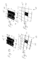
- FIG. 5 shows a roof tile 14 as it is used to cover a roof 15 on the side next to a window 16. The latter can be seen in the section of the roof 15 of FIG. 5.1.
- FIG. 6 shows the roof tile 17 for the upper edge 18 of a flat roof 19.
- a corner 20 of the associated building can be seen in FIG. 6.1.
- the roof tile 17 has a pulled-down upper edge 21.
- FIG. 7 shows a flat roof tile 22 as it is used as the lower end of a roof 23.
- the lower edge 24 of the tile 22 is extended downwards, so that the formation of a roof termination 25 and transition into a gutter 26 is created; the latter can be seen from FIG. 7.1.
- FIG. 8.1 An angled roof tile 27 can be seen in FIG. The bend by the angle a takes place along a line 28 which divides the roof tile 27 into the two partial lengths L1 and L2, both of which are approximately of the same length.
- the roof tile 27 serves, for example, to cover a mansard roof 29, of which FIG. 8.1 shows a section.
- FIG. 9 shows a ridge tile 30 and FIG. 9.1 the associated section from a ridge 31.
- FIG. 10 shows the ridge tile 32 for the left-hand end of a roof ridge 31, while FIG. 11 shows the ridge tile 33 for the right-hand end of a roof ridge 31.
- the roof ridges 31 can be seen in the associated sections of FIGS. 10.1 and 11.1.
- FIG. 12 shows the end cap 34 for the ridge 35 of a hipped caterpillar 36, of which the associated section can be seen in FIG. 12.1.
- the end cap 34 has the three edge lengths L1, L2 and L3 with the intermediate transition sections 37 with the respective widths B1, B2 and B3.
- the edge lengths L1, L2 and L3 and the widths B1, B2 and B3 are each about the same length, as can also be seen in the right part of FIG.
- the lower end tile 38 of a ridge caterpillar 39 can be seen, as it presents itself, for example, as the lower end of a hipped caterpillar 36.
- the end tile 38 has the two different widths B 1 and B 2.
- the detail from the lower corner part of a hawk gait 36 can be seen in FIG. 13.1.
- FIG. 14 shows a flat roof tile 40 which is provided with an attachment 41 which has an opening 42 at the bottom.
- the roof tile 40 serves to ventilate a roof structure 43, a section of which is shown in FIG. 14.1.
- FIG. 15 shows a roof tile 44 which has a feed-through 45 for an antenna mast or an exhaust pipe (not shown).
- the bushing 45 has the diameter "a”.
- the respective distances "b” and “c” from the lower edge 46 and upper edge 47 of the roof tile 44 are indicated in FIG. 15, whereby these distances "b” and “c” can be the same size or different sizes.
- the arrangement of the roof tile 44 below a roof structure 48 is shown in FIG. 15.1.
- the bushing 45 has a round cross section.
- FIGS. 1 to 5 form only a section of the various possibilities for designing roof tiles from the waste containing plastics and fillers described.
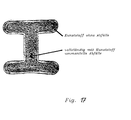
- FIG. 16 shows a schematic representation of a system according to the invention and FIG. 17 shows a cross section through a molded part produced by the method according to the invention, this molded part being designed as a double-T support.
- Unsorted waste plastics such as plastic bottles of detergents or fabric softeners or the like, are fed from a conveyor belt 48 into the comminution system 53, which as so-called Shredder can be formed.
- the comminution system 53 carries out the desired comminution, the comminuted product falling over the feed hopper 54 onto a further conveyor belt 56, so that a conveying direction in the direction of arrow 62 is created.
- the shredded material is transferred from the conveyor belt 56 to a conveyor belt 50 in order to be transported by this conveyor belt 50 in the direction of the arrow 63.
- the shredding system 53 not only unsorted old plastics but also other fillers, such as wood or paper, can be shredded if required.
- the conveyor belt 57 transfers the comminuted material to the conveyor belt 50.
- a respective quantity control not shown here, ensures that the substances are fed to the conveyor belt in the desired proportions.
- the conveyor belt 50 now conveys these substances in the direction of arrow 63 onto the conveyor belt 51, which in turn transports these substances in the direction of arrow 64, whereupon these substances fall at the end of the conveyor belt 51 in the direction of arrow 65 into the hopper 58 of an extruder 59 and taken over by the extruder and transported by the extruder screw in the direction of arrow 66 and thereby pressed and heated.
- Heating by pressing in the extruder screw alone can be sufficient. However, separate heating can also be provided in a known manner. In the extruder 59, the mixture of plastic and filler is pressed and, if necessary, the plastic is pulpy or liquid using the additional heating, so that it can be transported into a mold 60 at the end of the extruder.
- the basic structure is only required for the comminuted material emerging from the comminution devices to get into the extruder in some way and from there into a mold for producing the desired molded parts.
- the mode of transportation and the associated means of transportation to accomplish this are of secondary importance.
- plastics can be shredded together with the composites adhering to them.
- the parts comminuted in this way which consist of plastic and composite material, can be introduced into the extruder 59 without separating the composite material.
- the mold 60 represents a mold for producing a double-T profile
- a double-T profile with a cross section according to FIG. 17 is produced.
- a profile with an outer, enveloping surface was created Wall with a thickness of more than 1 mm, which consists exclusively of plastic and contains no fillers.
- the cavity enclosed by this wall is filled with filler and plastic, the shredded filler pieces being completely enclosed by plastic.
- the plastic thus envelops the filler parts and connects to one another and to the outer wall in the pasty state and then hardens.
- the result is a very resistant molded part with a smooth surface that can be colored in any way, which does not swell or does not swell appreciably in water and only shows a water absorption of 0.03 to 0.04%.
- the elastic properties of the molded part can be influenced. Observations have shown that any PVC components cannot release chlorine gas to the outside during the extrusion, but rather that any escaping chlorine gas is completely enclosed and held in place by the thermoplastic. In any case, chlorine gas escape cannot be observed on the extruder despite PVC components present in the extruder (e.g. 1% of the total mass).
- This roof tile 67 could in itself be counted among the various roof tiles described according to FIGS. 1 to 15. However, a special feature should be pointed out here in the roof tile 67 produced according to FIG.
- This roof tile 67 which is not shown completely, but of which only the resting end 69 is shown, has an overlap 68 on its right longitudinal side, which overlaps a corresponding support part 71 on the longitudinal side of an adjacent tile. This support part 71 naturally has every single roof tile and thus also the roof tile 67 shown on its left long side.
- This support part 71 is separated from an adjacent support piece 74 by a groove 75 which extends along the entire length of the pan. At the lying end 67, however, the support part 71 continues in a nose 72 which covers a part of the groove 75 in the transverse direction and has a length 73. This length 73 can be very short in relation to the length of the roof tile.
- this On the lateral longitudinal edge of the overlap 68, this has a rear engagement nose 70 at the bottom, which length may correspond to the length 73.
- These dimensions of the rear grip nose 70, the nose 72 and the groove 75 are chosen so that when an adjacent pan is inserted, it is placed at least offset by upwards by the amount 73, so that the nose 70 can dip into the groove 75. Then this adjacent roof tile is shifted downwards by the amount 73, so that the rear grip nose 70 now engages under the nose 72.
- all roof tiles in a row are connected to one another, so that not a single roof tile can be raised, but rather the entire row always follows when a single roof tile is raised. This means an additional covering security especially in case of wind attack.
Abstract
Description
Ein Verfahren zur Herstellung von Formteilen der eingangs beschriebenen Art ist bekannt geworden aus der DE-OS 39 39 189. Bei diesem Verfahren werden bereits Kunststoffabfälle verwertet. Diese Kunststoffabfälle müssen jedoch in reiner Form vorliegen und daher, soweit sie als Ausgangsmaterial nicht rein vorhanden sind, gereinigt und von evtl. Begleitern, wie z. B. Verbundstoffen, befreit werden. Das Kunststoffausgangsmaterial wird damit teuer und es fallen außerdem die bei der Reinigung anfallenden Stoffe und die abgetrennten Begleiter als zu entsorgender Abfall an.A process for the production of molded parts of the type described in the introduction has become known from DE-OS 39 39 189. Plastic waste is already used in this process. However, this plastic waste must be in pure form and therefore, as far as it is not available as a starting material, cleaned and possibly by companions, such as. B. composites are exempt. This makes the plastic raw material expensive and the substances that arise during cleaning and the separated companions also arise as waste to be disposed of.
Darüber hinaus ist ganz allgemein die Verwertung von thermoplastischen Kunststoffabfällen bekannt durch den Aufsatz von Tenner, Helmut: "Aufbereitung von thermoplastischen Abfällen in der Schmelze" in dem Buch "Verwerten von thermoplastischen Kunststoffabfällen", Herausgeber: VDI-Gesellschaft Kunststofftechnik, 1979, Düsseldorf, VDI-Verlag, Seiten 63 bis 77.In addition, the recycling of thermoplastic waste is generally known through the article by Tenner, Helmut: "Processing of thermoplastic waste in the melt" in the book "Recycling thermoplastic waste", publisher: VDI-Gesellschaft Kunststofftechnik, 1979, Düsseldorf, VDI -Publisher,
Darüber hinaus ist es mit dem deutschen Gebrauchsmuster G 1 926 870 bekannt, Dachpfannen aus einem transparenten Kunststoff herzustellen, die lichtdurchlässig sind und ein geringes Gewicht aufweisen. Zur Erreichung dieser Lichtdurchlässigkeit müssen hochwertige Kunststoffe verwendet werden, wodurch diese Dachpfanne in der Herstellung teuer wird. Für eine vollständige Dachabdekkung ist darüber hinaus die Lichtdurchlässigkeit nicht erwünscht. Außerdem sind diese bekannten Dachpfannen aus Kunststoff leicht entflammbar und entsprechen daher nicht den Sicherheitsbestimmungen.In addition, it is known with the German utility model G 1 926 870 to produce roof tiles from a transparent plastic which are translucent and light in weight. To achieve this light transmission, high-quality plastics must be used, which makes this roof tile expensive to manufacture. In addition, the light transmission is not desirable for a complete roof covering. In addition, these known plastic roof tiles are easily flammable and therefore do not comply with the safety regulations.
Der Erfindung liegt somit die Aufgabe zugrunde, ein Verfahren ebenso wie eine Anlage zur Herstellung von Formteilen vorzuschlagen, mit dem bzw. mit der eine billigere Produktion solcher Formteile möglich ist.The invention is therefore based on the object of proposing a method and an installation for the production of molded parts with which a cheaper production of such molded parts is possible.
Verfahrensmäßig ist diese Aufgabe dadurch gelöst, daß ein Gemenge, enthaltend ungereinigte Alt-Kunststoffe, die thermoplastische Anteile aufweisen, sowie Füllstoffe zerkleinert und anschließend in einem geeigneten Verhältnis einem Extruder zugeführt werden, worauf die am Kopf des Extruders austretende breiige Masse in eine Form zur Formgebung der Formteile getrieben wird. Die ungereinigten Alt-Kunststoffe und Füllstoffe können ohne weitere Aufbereitung z. B. dem getrennten Hausmüll entnommen werden, der bestehen kann aus beliebigen Kunststoffen wie, z. B. Kunststoff-Tüten, aber auch zusätzlich aus beliebigen Verbundstoffen, die Kunststoff enthalten, wie z. B. kunststoffbeschichtete und aluminiumbeschichtete bzw. zusätzlich papierbeschichtete Flüssigkeitsbehälter sowie sonstigen zellulosehaltigen Stoffen, wie Papier oder Pappe. Es können auch nicht-thermoplastische Kunststoffe und sogar Metallteile, wie z. B. metallene Getränkedosen, enthalten sein, wobei dies alles in der im Hausmüll typischerweise auftretenden Verteilung anfallen kann. Dieses z. B. dem Hausmüll entstammende Gemenge kann ohne weitere Vorbehandlung unmittelbar zerkleinert und in zerkleinerter Form einem Extruder zugeführt werden. Im Extruder schmelzen die thermoplastischen Bestandteile auf und umhüllen die nicht schmelzbaren Bestandteile, auch soweit es sich dabei um Duroplaste, Metalle oder Zellulosefasern handelt. Erfahrungsgemäß ist in dem Gemenge immer ein Bestandteil von etwa 1 % PVC enthalten, wodurch zunächst zu erwarten gewesen wäre, daß während der Verarbeitung im Extruder giftige Chlorgase entstehen und entweichen. Die Erfahrung zeigt jedoch, daß keinerlei Chlorgase austreten, da diese offenbar bereits mit oder vor ihrem Entstehen von den bereits breiig oder flüssig gewordenen Kunststoffanteilen gefangen und eingeschlossen werden.In procedural terms, this object is achieved in that a mixture containing unpurified waste plastics, which have thermoplastic components, and fillers are comminuted and then fed to an extruder in a suitable ratio, whereupon the pulpy mass emerging at the head of the extruder is shaped into a mold the molded parts is driven. The uncleaned old plastics and fillers can be processed without further processing e.g. B. the separate household waste, which can consist of any plastics such as. B. plastic bags, but also from any composite materials that contain plastic, such as. B. plastic-coated and aluminum-coated or additionally paper-coated liquid containers and other cellulose-containing substances such as paper or cardboard. It can also non-thermoplastic materials and even metal parts such. B. metal beverage cans may be included, all of which may occur in the distribution typically occurring in household waste. This z. B. the domestic waste can be comminuted without further pretreatment and fed to an extruder in comminuted form. The thermoplastic components melt in the extruder and envelop the non-meltable components, even if they are thermosets, metals or cellulose fibers. Experience has shown that there is always a component of about 1% PVC in the batch, which would initially have been expected to produce and escape toxic chlorine gases during processing in the extruder. Experience shows, however, that no chlorine gases escape, since these are apparently trapped and enclosed with or before their formation by the plastic parts that have already become mushy or liquid.
Die beschriebene Lösung erlaubt somit die Verwendung von minderwertigsten Abfällen, aus denen ein hochwertiges Produkt mit ausgezeichneten Festigkeitseigenschaften hergestellt werden kann. Die Abfallkunststoffe werden unsortiert und mit daran anhaftenden Verbundstoffen, wie z. B.The solution described thus allows the use of low-quality waste, from which a high-quality product with excellent strength properties can be produced. The waste plastics are unsorted and with adhering composites, such as. B.
Aluminiumfolie oder Papier, einschl. weiterer darin enthaltener Abfallstoffe ohne weiteren Trennvorgang einfach zerkleinert und ungetrennt und unsortiert in den Extruder gegeben. Verblüffenderweise kann hierbei festgestellt werden, daß sich eine geschlossene Außenhaut aus Kunststoff ohne Beimischungen bildet, während alle Füllstoffe und Abfallstoffe, wie z. B. die am Altkunststoff anhaftenden Verbundstoffe, nach innen wandern und dort Partikel für Partikel vollständig von Kunststoff umgeben sind. Die Füllstoffe können hierbei vorzugsweise einen Anteil von 50 Gewichtsprozent annehmen.Aluminum foil or paper, including other waste materials contained therein, simply shredded and separated into the extruder without being separated and unsorted. Surprisingly, it can be stated that a closed outer skin made of plastic without admixtures forms, while all fillers and waste materials, such as. B. the adhesives adhering to the old plastic, migrate inwards and there are particles for particles completely surrounded by plastic. The fillers can preferably assume a proportion of 50 percent by weight.
Die zerkleinerten Füllstoffe werden alle in das Innere des hergestellten Formteils gedrängt und dort nicht etwa in ihrer Gesamtheit sondern partikelweise mit Kunststoff umhüllt. Der breiige Kunststoff verbindet sich hierbei auch untereinander und verbindet sich ebenfalls mit der äußeren Kunststoffhaut, in der keine Füllstoffe vorhanden sind. Diese äußere Kunststoffhaut kann mehr als 1 mm dick sein. Es entsteht hierdurch ein sehr festes Formteil, das nur in außerordentlich geringem Maße Wasser aufnimmt. Aufgrund der geringen Wasseraufnahmefähigkeit tritt auch, im Gegensatz zu sonstigen Kunststoffteilen keine Quellung im Wasser auf.The shredded fillers are all pushed into the interior of the molded part and are not covered with plastic in their entirety but in particles. The pulpy plastic also bonds with each other and also connects with the outer plastic skin, in which there are no fillers. This outer plastic skin can be more than 1 mm thick. This creates a very solid molded part that absorbs water only to an extremely small extent. Due to the low water absorption capacity, in contrast to other plastic parts, there is no swelling in the water.
Eine besondere Art des beschriebenen Verfahrens liegt darin, daß die breiige Masse durch die Form bei gleichen Abmessungen und zumindest annähernd gleichem Gewicht in die einem aus Ton oder tonhaltigen Massen gebrannten oder aus Beton gegossenen Dachziegel entsprechende Formgestalt gebracht wird. Hierbei kann der Druck in der zugeordneten Form vorzugsweise in der Größenordnung von 250 Bar liegen. Die auf solche Art hergestellten Dachpfannen sind hochfest und aufgrund ihrer starken Pressung flammwidrig. Sie sind in ihrer Handhabung - was dem zuständigen Handwerker angenehm ist - nahezu identisch mit den bekannten Dachpfannen aus Ton oder tonhaltigen Massen oder aus gegossenem Beton. Darüber hinaus können sie jedoch beliebig eingefärbt werden und sehr leicht an Ort und Stelle zur Anpassung an örtliche Gegebenheiten mit Handarbeitsgeräten geschnitten werden, ohne daß hierbei Bruchgefahr besteht. Natürlich können solche Dachpfannen beliebig profiliert sein, z. B. in der Form von Dachplatten oder Wellplatten geformt sein, die jeweils nicht nur für eine Dachabdeckung geeignet sind. Beim Transport müssen solche Dachpfannen nicht vorsichtig gehandhabt werden, sondern können beispielsweise an der Baustelle ohne Bruchgefahr einfach abgekippt werden. Durch die Verwendung des eingangs beschriebenen minderwertigsten Abfallstoffes wird dennoch die Herstellung dieser Dachpfannen sehr billig. Es ist darüber hinaus möglich, im Verlaufe des Verfahrens zur Herstellung der Formteile Zusätze zuzugeben, die die Fertigprodukte flammwidrig machen. Ein solcher Zusatz kann z. B. Magnesiumhydroxid sein. Entsprechende Zubereitungen sind im Handel erhältlich, z. B. unter der Bezeichnung Magnifin H10 der Firma Martinswerk GmbH in 5010 Bergheim.A special type of the method described is that the mushy mass is brought by the shape with the same dimensions and at least approximately the same weight into the shape corresponding to a shape made of clay or clay-containing masses or cast from concrete roof tiles. Here, the pressure in the assigned form, preferably in size order of 250 bar. The roof tiles produced in this way are high-strength and flame-retardant due to their strong pressure. Their handling - which is convenient for the responsible craftsman - is almost identical to the well-known roof tiles made of clay or clay-containing masses or made of poured concrete. In addition, however, they can be colored as desired and cut very easily on site to adapt to local conditions using hand-held tools without the risk of breakage. Of course, such roof tiles can be profiled, z. B. in the form of roof panels or corrugated panels, which are each not only suitable for a roof covering. Such roof tiles do not have to be handled carefully during transport, but can simply be tipped over at the construction site without the risk of breakage. The use of the inferior waste material described at the beginning makes the production of these roof tiles very cheap. It is also possible to add additives in the course of the process for the production of the molded parts which make the finished products flame-retardant. Such an addition can e.g. B. be magnesium hydroxide. Appropriate preparations are commercially available, for. B. under the name Magnifin H10 from Martinswerk GmbH in 5010 Bergheim.
Eine Anlage zur Durchführung des erfindungsgemäßen Verfahrens zeichnet sich aus durch mindestens eine Zerkleinerungseinrichtung zur Zerkleinerung der ungereinigten Alt-Kunststoffe und der Füllstoffe, die über Transportmittel mit einem zugeordneten Extruder verbunden ist bzw. sind, der seinerseits mit einer Form zur Herstellung der Formteile verbunden ist. Die Anlage zur Durchführung des Verfahrens ist somit sehr einfach aufgebaut. Die Transportmittel können einfache Förderbänder sein. Im Prinzip reicht eine Zerkleinerungseinrichtung zur Zerkleinerung aus. Falls Kunststoffe mit Verbundstoffen zerkleinert werden, kann es sein, daß der Anteil der Verbundstoffe als Füllstoff bereits eine gewünschte Menge einnimmt. Falls mehr Füllstoff verwendet werden soll, ist es möglich, derZerkleinerungseinrichtung z. B. Abfallpapiere in gewünschter Menge beizugeben. Sowohl die Abfallpapiere als auch die unsortierten Kunststoffe werden dann von der gleichen Zerkleinerungseinrichtung zerkleinert.A plant for carrying out the method according to the invention is characterized by at least one comminution device for comminuting the unpurified old plastics and the fillers, which is or are connected by means of transport to an associated extruder, which in turn is connected to a mold for producing the molded parts. The system for carrying out the method is therefore very simple. The means of transport can be simple conveyor belts. In principle, a shredding device is sufficient for shredding. If plastics are shredded with composites, the proportion of the composites as filler may already be in a desired amount. If more filler is to be used, it is possible to use e.g. B. Add waste papers in the desired amount. Both the waste paper and the unsorted plastics are then shredded by the same shredding device.
Es ist jedoch auch möglich eine weitere Zerkleinerungseinrichtung für solche Füllstoffe vorzusehen, die nicht als Verbundstoffe dem Kunststoff anhaften. Aus der einen oder aus beiden Zerkleinerungseinrichtungen werden dann die zerkleinerten Produkte z. B. über einfache Förderbänder dem Extruder zugeführt. Hierbei ist es auch möglich, daß die aus den Zerkleinerungseinrichtungen kommenden Produkte zunächst noch in einem Zwischenlager gespeichert werden und sodann in einem gewünschten Verhältnis über die Transporteinrichtung dem Extruder zugeführt werden. Es ist auch möglich, die zerkleinerten Kunststoffteile und und Füllstoffteile zunächst noch im gewünschten Verhältnis miteinander zu mischen und sodann erst das gemischte Produkt über die Transporteinrichtungen dem Extruder zuzuführen.However, it is also possible to provide a further comminution device for fillers which do not adhere to the plastic as composite materials. From the one or both shredding devices, the shredded products are then z. B. fed to the extruder via simple conveyor belts. It is also possible here that the products coming from the shredding devices are first stored in an intermediate store and then fed to the extruder in a desired ratio via the transport device. It is also possible to first mix the shredded plastic parts and filler parts together in the desired ratio and only then to feed the mixed product to the extruder via the transport devices.
Im Extruder wird die zerkleinert Mischung durch den Extruderdruck oder durch eine gesonderte Heizung erwärmt, wobei der Kunststoff je nach Erwärmungsgrad breiig oder flüssig wird und in dieser Form zusammen mit den eingelagerten Füllstoffpartikeln in die Form für das Formteil gepreßt wird.In the extruder, the comminuted mixture is heated by the extruder pressure or by a separate heater, the plastic becoming mushy or liquid, depending on the degree of heating, and is pressed in this form together with the stored filler particles into the mold for the molded part.
Als Füllstoffe können sehr viele Stoffe verwendet werden, was schon daran zu erkennen ist, daß die unterschiedlichsten modernen Kunststoffbehälter vielerlei Verbundstoffe aufweisen, die allesamt als Füllstoff verwendet werden können. So ist auch z. B. die Verwendung von Holz als Füllstoff problemlos möglich. Wegen der vollständigen Umhüllung der zerkleinerten Holzteile mit Kunststoff kann ebenso wie Papier so auch Holz als Füllstoff kein Wasser aufnehmen. Die Art der verwendeten Füllstoffe kann jedoch die elastischen Eigenschaften und die Festigkeitseigenschaften des hergestellten Formteils in gewünschter Weise beeinflussen.A great number of substances can be used as fillers, which can already be seen from the fact that the most varied of modern plastic containers have many different composite materials, all of which can be used as fillers. So is z. B. the use of wood as a filler is no problem. Because the shredded wooden parts are completely covered with plastic, just like paper, wood as a filler cannot absorb water. However, the type of fillers used can influence the elastic properties and the strength properties of the molded part in a desired manner.
Die Erfindung betrifft weiter ein Formteil, hergestellt nach dem erfindungsgemäßen Verfahren, daß eine die äußere Oberfläche bildende Kunststoffhaut von etwa 1 mm dicke oder mehr, die einen mit Füllstoff und Kunststoff gefüllten Raum umschließt, aufweist, wobei die Füllstoffpartikel alle vollständig von Kunststoff ummantelt sind und wobei der innere Kunststoff und der äußere Kunststoff miteinander verbunden sind. Es handelt sich hierbei um ein außerordentlich preisgünstig herstellbares Formteil, daß feuchtigkeitsunempfindlich und formstabil ist und dessen elastische Eigenschaften durch die Art der gewählten Füllstoffe beeinflußbar sind.The invention further relates to a molded part, produced by the method according to the invention, that has a plastic skin of about 1 mm thick or more which forms the outer surface and encloses a space filled with filler and plastic, the filler particles all being completely encased in plastic and wherein the inner plastic and the outer plastic are interconnected. It is an extremely inexpensive molded part that is insensitive to moisture and stable in shape and whose elastic properties can be influenced by the type of fillers selected.
Ein besonders günstiges Formteil, hergestellt nach dem erfindungsgemäßen Verfahren, liegt vor, wenn das Formteil bei gleichen Abmessungen und zumindest annähernd gleichem Gewicht die einem aus Ton oder tonhaltigen Massen gebrannten oder aus Beton gegossenen Dachziegel entsprechende Formgestalt aufweist. Hierdurch gelingt es, aus minderwertigstem Abfallmaterial hochwertige Dachziegel herzustellen, die sich für den einschlägigen Fachmann handhaben lassen wie bekannte Dachziegel des Standes der Technik. Bekannte Dachziegel aus Ton oder Beton haben ein Gewicht zwischen 2500 und 3500 gr pro Stück, welches erforderlich ist, um ein Abheben bei starkem Wind zu verhindern. Bei der erfindungsgemäßen Verarbeitung der Abfälle wird ein Gewicht der Recylingdachpfannen von mehr als 30 KG/qm erreicht, welches beim Zugrundelegen von üblichen Abmessungen von Flachdachpfannen einem Gewicht von 3800 g/Stück entspricht. Durch die Verwendung des eingangs beschriebenen Abfallgemisches ist damit ein Werkstoff gefunden worden, der vom Gewicht her vorzüglich geeignet ist, Ton und Beton als Werkstoff für Dachziegel zu ersetzen. Die Dachziegel können in den gleichen zugleich genormten Abmessungen, auch was deren Dicke betrifft, gefertigt werden, wie die Erzeugnisse aus Ton oder Beton, jedoch mit erheblich größerer Genauigkeit. Die Formmassen lassen sich darüber hinaus auch gut einfärben oder gut von außen färben, so daß man Dachziegel erhält, die vollkommen durchgefärbt sind oder von außen gefärbt sind. Sie können damit ohne Schwierigkeiten in allen modernen Farben hergestellt werden. Die nach dem erfindungsgemäßen Verfahren hergestellten, neuartigen Dachziegel haben die gleichen Abmessungen und Wellenstrukturen, wie aus Ton oder tonhaltigen Massen gebrannte oder aus Beton gegossene Dachziegel. Ihre Oberfläche kann vollkommen glatt sein, wodurch sie in ihrem Aussehen mehr in die Nähe von glasierten Dachziegeln gerückt sind. Die glatte Oberfläche hat den besonderen Vorteil, daß die erfindungsgemäßen Dachziegel frei bleiben von Bemoosung und Bewuchs.A particularly favorable molded part, produced by the method according to the invention, is present when the molded part has the same shape as the roof tile, which is fired from clay or clay-containing masses or cast from concrete, with the same dimensions and at least approximately the same weight. This makes it possible to produce high-quality roof tiles from the lowest-quality waste material, which can be handled by the relevant specialist like known roof tiles of the prior art. Known roof tiles made of clay or concrete have a weight between 2500 and 3500 gr per piece, which is necessary to prevent lifting in strong winds. In the processing according to the invention The waste of the recycling roof tiles of more than 30 KG / sqm is reached, which corresponds to a weight of 3800 g / piece when using the usual dimensions of flat roof tiles. By using the waste mixture described at the outset, a material has been found that is excellently suited in terms of weight to replace clay and concrete as a material for roof tiles. The roof tiles can be made in the same standardized dimensions, also in terms of their thickness, as the products made of clay or concrete, but with considerably greater accuracy. The molding compounds can also be colored well or colored well from the outside, so that you get roof tiles that are completely colored or colored from the outside. They can be produced in all modern colors without difficulty. The novel roof tiles produced by the method according to the invention have the same dimensions and wave structures as roof tiles fired from clay or clay-containing masses or cast from concrete. Their surface can be completely smooth, which means that their appearance has moved them closer to glazed roof tiles. The smooth surface has the particular advantage that the roof tiles according to the invention remain free from moss and vegetation.
Die durch die weiter oben beschriebenen Zusätze zur Formmasse flammwidrig eingestellten Dachziegel erfüllen die DIN 4102 für schwer entflammbare Baustoffe.The roof tiles made flame-retardant by the additives to the molding compound described above meet DIN 4102 for flame-retardant building materials.
Das erfindungsgemäße Verfahren erlaubt eine sehr maß- und formgenaue Herstellung der Dachpfannen, so daß beim Einbau eine hohe Anlagegenauigkeit und damit eine hohe Winddichtigkeit erreicht wird. Alle Kanten und Ecken können ausreichend gerundet sein.The method according to the invention allows the roof tiles to be produced in a very precise and precise manner, so that a high degree of system accuracy and thus a high level of windproofness are achieved during installation. All edges and corners can be rounded sufficiently.
Die nach dem erfindungsgemäßen Verfahren hergestellten Dachziegel können alle gängigen aber auch neue Formen aufweisen und können darüber hinaus in beliebigen Maßvarianten und auch in beliebigen Dicken hergestellt werden.The roof tiles produced according to the method according to the invention can have all the usual but also new shapes and can also be produced in any size variants and also in any thicknesses.
Eine Besonderheit der nach dem erfindungsgemäßen Verfahren hergestellten Dachpfanne ist noch darin zu sehen, daß die Dachpfanne an einer Seite einen sich über die ganze Länge erstreckenden Übergriff aufweist, der, beginnend am aufliegenden Ende auf der Unterseite eine sich über einen kleineren Teil der Länge der Dachpfanne erstreckende Hintergriffnase aufweist, der an der anderen Längsseite der Dachpfanne am Auflageteil für den Übergriff eine Nase entsprechender Länge zugeordnet ist. Auf diese Art und Weise könne alle Dachpfannen einer Reihe beim Verlegen im Bereich ihrer Längskanten miteinander verbunden werden, so daß dann, wenn ein Dachziegel angehoben wird, die gesamte Reihe mit angehoben werden muß. Dies ergibt eine noch höhere Abdecksicherheit bei Windangriff.A peculiarity of the roof tile produced by the method according to the invention can still be seen in the fact that the roof tile has on one side an overlap which extends over the entire length and which, starting at the overlying end on the underside, extends over a smaller part of the length of the roof tile extending rear grip nose, which is assigned a nose of corresponding length on the other long side of the roof tile on the support part for the overlap. In this way, all roof tiles in a row can be connected to each other when laying in the area of their longitudinal edges, so that when a roof tile is raised, the entire row must also be lifted. This results in an even higher covering security in the event of a wind attack.
Nach dem erfindungsgemäßen Verfahren können selbstverständlich nicht nur Dachziegel sondern nahezu beliebige Formteile, wie z. B. ein T-Träger oder ein Doppel-T-Träger oder andere Formprofile, hergestellt werden. Die letztgenannten Formkörper können auch problemlos als Strangpreßprofile nach dem erfindungsgemäßen Verfahren hergestellt werden. Es ist lediglich erforderlich, den Austritt des Extruders entsprechend zu gestalten.According to the method of the invention can of course not only roof tiles but almost any shape, such. B. a T-beam or a double-T beam or other shape profiles can be produced. The last-mentioned shaped bodies can also be produced without problems as extruded profiles by the process according to the invention. It is only necessary to design the outlet of the extruder accordingly.
Im Rahmen der Aufzählung der Vorteile bleibt schließlich noch die Tatsache zu erwähnen, daß durch die Verwendung des Gemisches von Kunststoffabfällen und Füllstoffen und deren Wiederverwertung die kommunalen Deponien in erheblichem Umfang entlastet werden.Finally, in the context of the list of advantages, the fact remains that the use of the mixture of plastic waste and fillers and their recycling significantly reduces the burden on municipal landfills.
Die Erfindung soll nachfolgend anhand der beigefügten Zeichnungen näher erläutert werden.The invention will be explained in more detail with reference to the accompanying drawings.
Es zeigen:
Figur 1 bis 15 unterschiedliche Ausführungsformen von Dachziegeln hergestellt nach dem erfindungsgemäßen Verfahren- Figur 16 in schematischer Darstellung Anlage zur Durchführung des Verfahrens
Figur 17 weiteres Formteil im Querschnitt, hergestellt nach dem erfindungsgemäßen VerfahrenFigur 18 Dachpfanne in Teilperspektive, hergestellt nach dem erfindungsgemäßen Verfahren DieDachziegel der Figuren 1 bis 15 weisen die ihrer jeweiligen Länge L, Breite B und Höhe H entsprechende Hauptabmessungen auf. Weitere Maßangaben entsprechen untergeordneten Abmessungen.
- Figure 1 to 15 different embodiments of roof tiles manufactured by the inventive method
- Figure 16 is a schematic representation of the system for performing the method
- 17 shows another shaped part in cross section, produced by the method according to the invention
- FIG. 18 roof tile in partial perspective, produced by the method according to the invention. The roof tiles of FIGS. 1 to 15 have the main dimensions corresponding to their respective length L, width B and height H. Further dimensions correspond to subordinate dimensions.
Die Figur 1 zeigt eine Flachdachpfanne 1, wie sie zur Abdeckung von Dächern mit verhältnismäßig geringer Dachneigung geeignet und gebräuchlich ist, in perspektivischer Ansicht. Die Figur 1.1 zeigt die Draufsicht, die Figur 1.2 die Seitenansicht und die Figur 1.3 schließlich die Vorderansicht der Flachdachpfanne 1. Die Oberfläche 2 der Flachdachpfanne 1 ist, wie man an den Figuren 1 und 1.3 deutlich erkennt, doppelt gewellt.FIG. 1 shows a
Die Figur 2 zeigt eine der Figur 1 ähnliche Flachdachpfanne 3 von geringerer Breite. Die Oberfläche 4 der Flachdachpfanne 3 ist demgegenüber nur einfach gewellt. Die Figur 2.1 zeigt einen Ausschnitt aus einem Dach 5, wo Flachdachpfannen 3 und Flachdachpfannen 1 gemeinsam verlegt sind.FIG. 2 shows a
Die Figur 3 zeigt eine Pfanne 6 für einen seitlichen, linken Dachabschluß (Ortgangziegel). Den Ausschnitt aus dem zugehörigen Dach 7 läßt Figur 3.1 erkennen. Die Pfanne 6 hat eine seitliche Einziehung 8 an ihrem oberen Ende 9, wo sie von dem heruntergezogenen Rand 10 des Nachfolgeziegels 11 überlappt wird.FIG. 3 shows a
Die Figur 4 zeigt einen der Figur 3 entsprechenden Dachziegel 12 (Ortgangziegel) für einen rechtsseitigen Dachabschluß. Einen Ausschnitt aus einem solchen Dach 13 sieht man in der Figur 4.1.FIG. 4 shows a
In der Figur 5 ist eine Dachpfanne 14 wiedergegeben, wie sie zur Abdeckung eines Daches 15 seitlich neben einem Fenster 16 gebräuchlich ist. Letzteres ist in dem Ausschnitt des Daches 15 der Figur 5.1 zu sehen.FIG. 5 shows a
Die Figur 6 zeigt den Dachziegel 17 für den oberen Rand 18 eines flachen Daches 19. Von dem zugehörigen Gebäude ist in der Figur 6.1 eine Ecke 20 zu sehen. Der Dachziegel 17 hat einen weit heruntergezogenen oberen Rand 21.FIG. 6 shows the
Die Figur 7 zeigt einen flachen Dachziegel 22, wie er als unterer Abschluß eines Daches 23 gebräuchlich ist. Der untere Rand 24 des Dachziegels 22 ist nach unten hin verlängert, so daß die Bildung eines Dachabschlusses 25 und Übergang in eine Dachrinne 26 geschaffen wird; letzteres ist aus der Figur 7.1 erkennbar.FIG. 7 shows a
In der Figur 8 ist ein abgewinkelter Dachziegel 27 erkennbar. Die Abwinklung um den Winkel a erfolgt längs einer Linie 28, welche den Dachziegel 27 in die beiden Teillängen L1 und L2 unterteilt, die beide etwa gleich lang sind. Der Dachziegel 27 dient beispielsweise zur Abdeckung eines Mansardendaches 29, von dem die Figur 8.1 einen Ausschnitt zeigt.An
Die Figur 9 zeigt einen Firstziegel 30 und die Figur 9.1 den zugehörigen Ausschnitt aus einem Dachfirst 31.FIG. 9 shows a
Die Figur 10 zeigt den Firstziegel 32 für den linksseitigen Abschluß eines Dachfirsts 31, während die Figur 11 den Firstziegel 33 für den rechtsseitigen Abschluß eines Dachfirstes 31 wiedergibt. Die Dachfirste 31 sind in den zugehörigen Ausschnitten der Figuren 10.1 und 11.1 zu erkennen.FIG. 10 shows the
Die Figur 12 zeigt die Abschlußkappe 34 für den First 35 einer Walmgaupe 36, von der in der Figur 12.1 der zugehörige Ausschnitt zu sehen ist. Die Abschlußkappe 34 hat die drei Kantenlängen L1, L2 und L3 mit den dazwischen liegenden Übergangsabschnitten 37 mit den jeweiligen Breiten B1, B2 und B3. Die Kantenlängen L1, L2 und L3 sowie die Breiten B1, B2 und B3 sind jeweils etwa gleich lang, wie das auch in dem rechten Teil der Figur 12 erkennbar ist. In der Figur 13 ist der untere Abschlußziegel 38 einer Firstgaupe 39 zu erkennen, wie er sich beispielsweise als unterer Abschluß einer Walmgaupe 36 darbietet. Der Abschlußziegel 38 hat die beiden unterschiedlichen Breiten B 1 und B 2. Der Ausschnitt aus dem unteren Eckteil einer Walmgaupe 36 ist in der Figur 13.1 zu sehen.FIG. 12 shows the
Die Figur 14 zeigt eine flache Dachpfanne 40, die mit einem Aufsatz 41 versehen ist, der nach unten hin eine Öffnung 42 aufweist. Die Dachpfanne 40 dient zur Belüftung einer Dachkonstruktion 43, von der in der Figur 14.1 ein Ausschnitt gezeigt ist.FIG. 14 shows a
In der Figur 15 schließlich ist eine Dachpfanne 44 gezeigt, welche eine Durchführung 45 für einen Antennenmast oder ein Dunstrohr (nicht gezeigt) aufweist. Die Durchführung 45 hat den Durchmesser "a". Die jeweiligen Abstände "b" und "c" vom unteren Rand 46 bzw. oberen Rand 47 der Dachpfanne 44 sind in der Figur 15 angedeutet, wobei diese Abstände "b" und "c" gleichgroß oder unterschiedlich groß sein können. Die Anordnung der Dachpfanne 44 unterhalb einer Dachkonstruktion 48 zeigt die Figur 15.1. Die Durchführung 45 hat einen runden Querschnitt.Finally, FIG. 15 shows a
Die in den Figuren 1 bis 5 gezeigten Ausführungsbeispiele bilden nur einen Ausschnitt aus den vielfältigen Möglichkeiten zur Ausgestaltung von Dachziegeln aus den beschriebenen Kunststoffe und Füllstoffe enthaltenden Abfällen.The exemplary embodiments shown in FIGS. 1 to 5 form only a section of the various possibilities for designing roof tiles from the waste containing plastics and fillers described.
Für die mit dem Verlegen der erfindungsgemäßen Dachziegel betrauten Dachdecker bieten diese eine Reihe von besonderen Vorteilen, die nachfolgend aufgezählt seien:
- - gleiche Dachkonstruktion,
- - gleiche Verlegegetechnik wie bei aus Ton oder tonhaltigen Massen gebrannten oder aus Beton gegossenen Dachziegeln,
- - leichte Bearbeitung z. B. mit Hilfe von Stichsägen,
- - keine Verletzungsgefahr durch scharfe Kanten,
- - kein Bruch beim Lagern, Transport und Verlegen,
- - genaues Verlegen aufgrund geringer Fertigungstoleranzen,
- - durch das genaue Verlegen bedingt verringertes Risiko der ungewollten Dachabdekkung durch Sturm,
- - preisgünstiges und dauerhaftes Produkt aus wiederverwenteden Abfallstoffen,
- - Begehbarkeit und Abkippbarkeit ohne Bruchrisiko.
- - same roof construction,
- - same laying technique as for roof tiles made of clay or clay-containing masses or cast from concrete,
- - Easy editing z. B. with the help of jigsaws,
- - no risk of injury from sharp edges,
- - no breakage during storage, transport and laying,
- - precise laying due to low manufacturing tolerances,
- - reduced risk of unwanted roofing due to storm due to the precise laying,
- - inexpensive and durable product made from reused waste materials,
- - Accessibility and tiltability without risk of breakage.
Die Figur 16 zeigt in schematischer Darstellung eine erfindungsgemäße Anlage und die Figur 17 zeigt einen Querschnitt durch ein nach dem erfindungsgemäßen Verfahren hergestelltes Formteil, wobei dieses Formteil als Doppel-T-Träger ausgebildet ist.16 shows a schematic representation of a system according to the invention and FIG. 17 shows a cross section through a molded part produced by the method according to the invention, this molded part being designed as a double-T support.
Von einem Förderband 48 werden unsortierte Altkunststoffe, wie z.B. Kunststoffflaschen von Waschmitteln oder Weichspülern oder ähnlichem in die Zerkleinerungsanlage 53 gegeben, die als sogen. Schredder ausgebildet sein kann. Die Zerkleinerungsanlage 53 führt die gewünschte Zerkleinerung durch, wobei das zerkleinerte Produkt über den Aufgabetrichter 54 auf ein weiteres Förderband 56 fällt, so daß eine Förderrichtung in Richtung des Pfeils 62 entsteht. Vom Förderband 56 wird das zerkleinerte Material auf ein Förderband 50 übergeben, um von diesem Förderband 50 in Richtung des Pfeils 63 transportiert zu werden. Mit der Zerkleinerungsanlage 53 können nicht nur unsortierte Altkunststoffe, sondern bei Bedarf auch andere Füllstoffe, wie z.B. Holz oder Papier, zerkleinert werden. Dies hängt ganz davon ab, womit die Zerkleinerungsanlage 53 beschickt wird. Es ist dann, wenn die Zerkleinerungsanlage 53 mit unterschiedlichen Materialien beschickt werden soll, erforderlich, daß diese Materialien jeweils zunächst in einen nicht näher dargestellten Zwischenspeicher geführt und von dort in einem gewünschten Verhältnis auf das Förderband 50 aufgegeben werden oder zunächst in einem gewünschten Verhältnis miteinander vermischt und sodann auf das Förderband 50 aufgegeben werden. Es ist aber auch denkbar, für andere Stoffe eine oder mehrere weitere Zerkleinerungseinrichtungen 52 vorzusehen, die von einem Förderband 49 beschickt werden können. Auch von dort wird das zerkleinerte Gut wieder über den Aufgabetrichter 55 auf ein weiteres Förderband 57 gegeben, so daß auch hier wieder eine Förderrichtung in Richtung des Pfeils 61 entsteht. Das Förderband 57 übergibt das zerkleinerte Gut an das Förderband 50. Eine jeweilige und hier nicht näher dargestellte Mengenkontrolle sorgt dafür, daß die Stoffe in den gewünschten Verhältnissen dem Förderband aufgegeben werden. Das Förderband 50 fördert nun diese Stoffe in Richtung des Pfeils 63 auf das Förderband 51, das seinerseits diese Stoffe in Richtung des Pfeils 64 transportiert, worauf diese Stoffe am Ende des Förderbandes 51 in Richtung des Pfeils 65 in den Einfülltrichter 58 eines Extruders 59 fallen und vom Extruder übernommen und von der Extruderschnecke in Richtung des Pfeils 66 transportiert und hierbei gepreßt und erhitzt werden. Die Erhitzung allein durch die Verpressung in der Extruderschnecke kann ausreichen. Es kann jedoch auch in bekannter Weise eine gesonderte Heizung vorgesehen sein. Im Extruder 59 wird das Gemenge aus Kunststoff und Füllstoff verpreßt und hierbei evtl. unter Einsatz der zusätzlichen Heizung der Kunststoff breiig oder flüssig, so, daß er am Ende des Extruders in eine Form 60 transportiert werden kann.Unsorted waste plastics, such as plastic bottles of detergents or fabric softeners or the like, are fed from a
Bei der Anlage nach Figur 16 ist vom Grundaufbau her lediglich erforderlich, daß das aus den Zerkleinerungseinrichtungen austretende, zerkleinerte Gut in irgendeiner Weise in den Extruder gelangt und von dort in eine Form zur Herstellung der angestrebten Formteile. Die Art und Weise des Transportes und die zugehörigen Transportmittel, um dies zu bewerkstelligen, sind von sekundärer Bedeutung.In the system according to FIG. 16, the basic structure is only required for the comminuted material emerging from the comminution devices to get into the extruder in some way and from there into a mold for producing the desired molded parts. The mode of transportation and the associated means of transportation to accomplish this are of secondary importance.
In den Zerkleinerungsanlagen 53 bzw. 52 können Kunststoffe zusammen mit den daran anhaftenden Verbundstoffen zerkleinert werden. Die so zerkleinerten Teile, die aus Kunststoff und Verbundwerkstoff bestehen, können ohne Trennung des Verbundwerkstoffes in den Extruder 59 eingebracht werden.In the
Stellt die Form 60 eine Form zur Herstellung eines Doppel-T-Profiles dar, so entsteht ein Doppel-T-Profil mit einem Querschnitt nach Figur 17. Überraschenderweise ist, ohne daß eine Coextrusion angewendet worden wäre, ein Profil entstanden mit einer äußeren, umhüllenden Wandung mit einer Dicke von mehr als 1 mm, die ausschließlich aus Kunststoff besteht und keine Füllstoffe enthält. Der von dieser Wand umschlossene Hohlraum ist aufgefüllt mit Füllstoff und Kunststoff, wobei die zerkleinerten Füllstoffstücke jeweils vollständig von Kunststoff umschlossen sind. Der Kunststoff umhüllt somit die Füllstoffteile und verbindet sich untereinander und mit der Außenwand im breiigen Zustand und härtet sodann aus. Es entsteht ein sehr widerstandsfähiges Formteil mit einer glatten und beliebig einfärbbaren Oberfläche, das in Wasser nicht oder nicht nennenswert quillt und nur eine Wasseraufnahme von 0,03 bis 0,04 % zeigt. Mit der Menge des Füllstoffs und der Zusammensetzung des Füllstoffs nach der Materialart können die elastischen Eigenschaften des Formteils beeinflußt werden. Beobachtungen haben gezeigt, daß evtl. PVC-Bestandteile während der Extrudierung kein Chlorgas nach außen abgeben können, sondern daß vielmehr evtl. austretendes Chlorgas von dem Thermoplast vollständig eingeschlossen und festgehalten wird. Jedenfalls kann am Extruder ein Entweichen von Chlorgas trotz im Extruder vorhandener PVC-Bestandteile (z. B. 1 % der Gesamtmasse) nicht beobachtet werden.If the
Es gelingt somit, aus Abfallstoffen, deren Wiederverwertung oder Entsorgung problematisch war, auf sehr preisgünstige Art und Weise ein wirtschaftlich hochwertiges Produkt herzustellen. Ein besonderes Beispiel hierzu ist die Dachpfanne 67 nach Figur 18. Diese Dachpfanne 67 könnte ansich zu den beschriebenen verschiedenen Dachpfannen nach den Figuren 1 bis 15 gezählt werden. Es soll jedoch hier bei der nach Figur 18 hergestellten Dachpfanne 67 auf eine Besonderheit hingewiesen werden. Diese Dachpfanne 67, die nicht vollständig dargestellt ist, sondern von der lediglich das aufliegende Ende 69 dargestellt ist, weist an ihrer rechten Längsseite einen Übergriff 68 auf, der ein entsprechendes Auflageteil 71 an der Längsseite einer benachbarten Pfanne übergreift. Dieses Auflageteil 71 weist natürlich jede einzelne Dachpfanne und so auch die dargestellte Dachpfanne 67 an ihrer linken Längsseite auf. Dieses Auflageteil 71 ist von einem benachbarten Tragstück 74 durch eine längs sich über die gesamte Pfannenlänge erstreckende Nut 75 getrennt. Am aufliegenden Ende 67 setzt sich jedoch der Auflageteil 71 in einer Nase 72 fort, die in Querrichtung einen Teil der Nut 75 überdeckt und eine Länge 73 aufweist. Diese Länge 73 kann in Relation zur Länge der Dachpfanne sehr kurz sein.It is thus possible to produce economically high-quality products from waste materials, the recycling or disposal of which was problematic. A special example of this is the
Am seitlichen Längsrand des Übergriffs 68 weist dieser unten eine Hintergriffnase 70 auf, die in ihrer Länge der Länge 73 entsprechen kann. Diese Abmessungen der Hintergriffnase 70, der Nase 72 und der Nut 75 sind so gewählt, daß beim Einsetzen einer benachbarten Pfanne diese mindestens um den Betrag 73 nach oben versetzt aufgelegt wird, so daß die Nase 70 in die Nut 75 eintauchen kann. Sodann wird diese benachbarte Dachpfanne um den Betrag 73 nach unten verschoben, so daß nunmehr die Hintergriffnase 70 die Nase 72 untergreift. Hierdurch sind alle Dachpfannen einer Reihe miteinander verbunden, so daß nicht eine einzelne Dachpfanne angehoben werden kann, sondern mit dem Anheben einer einzelnen Dachpfanne immer die gesamte Reihe folgt. Dies bedeutet eine zusätzliche Abdecksicherheit insbesondere bei Windangriff.On the lateral longitudinal edge of the overlap 68, this has a
- 1 Flachdachpfanne1 flat roof tile
- 2 Oberfläche, doppelt gewellt2 surface, double corrugated
- 3 Flachdachpfanne3 flat roof tiles
- 4 Oberfläche, einfach gewellt4 surface, simply corrugated
- 5 Dach5 roof
- 6 Pfanne6 pan
- 7 Dach7 roof
- 8 seitliche Einziehung8 side retraction
- 9 oberes Ende9 top end
- 10 heruntergezogener Rand10 edge pulled down
- 11 Nachfolgeziegel11 successor bricks
- 12 Dachziegel12 roof tiles
- 13 Dach13 roof
- 14 Dachpfanne14 roof tile
- 15 Dach15 roof
- 16 Fenster16 windows
- 17 Dachziegel17 roof tiles
- 18 Rand eines flachen Daches18 edge of a flat roof
- 19 flaches Dach19 flat roof
- 20 Ecke eines Gebäudes20 corner of a building
- 21 heruntergezogener oberer Rand21 pulled down top edge
- 22 flacher Dachziegel22 flat roof tiles
- 23 Dach23 roof
- 24 unterer Rand24 lower margin
- 25 Dachabschluß25 roof closure
- 26 Dachrinne26 gutter
- 27 abgewinkelter Dachziegel27 angled roof tiles
- 28 Teilungslinie28 dividing line
- 29 Mansardendach29 Mansard roof
- 30 Firstziegel30 ridge tiles
- 31 Dachfirst31 roof ridge
- 32 Firstziegel32 ridge tiles
- 33 Firstziegel33 ridge tiles
- 34 Abschlußkappe34 end cap
- 35 First35 First
- 36 Walmgaupe36 Walmgaupe
- 37 Übergangsabschnitt37 transition section
- 38 unterer Abschlußziegel38 lower finishing brick
- 39 Firstraupe39 caterpillar
- 40 Dachpfanne40 roof tile
- 41 Aufsatz41 essay
- 42 Öffnung42 opening
- 43 Dachkonstruktion43 roof construction
- 44 Dachpfanne44 roof tile
- 45 Durchführung45 Implementation
- 46 unterer Rand46 lower margin
- 47 oberer Rand47 top margin
- 48 Förderband48 conveyor belt
- 49 Förderband49 conveyor belt
- 50 Förderband50 conveyor belt
- 51 Förderband51 conveyor belt
- 52 Zerkleinerungseinrichtung52 Shredding device
- 53 Zerkleinerungsanlage53 shredding plant
- 54 Aufgabetrichter54 feed hopper
- 55 Aufgabetrichter55 feed hopper
- 56 Förderband56 conveyor belt
- 57 Förderband57 conveyor belt
- 58 Einfülltrichter58 hopper
- 59 Extruder59 extruders
- 60 Form60 form
- 61 Pfeil61 arrow
- 62 Pfeil62 arrow
- 63 Pfeil63 arrow
- 64 Pfeil64 arrow
- 65 Pfeil65 arrow
- 66 Pfeil66 arrow
- 67 Dachpfanne67 roof tile
- 68 Übergriff68 attack
- 69 aufliegendes Ende69 resting end
- 70 Hintergriffnase70 rear grip nose
- 71 Auflageteil71 support part
- 72 Nase72 nose
- 73 Länge73 length
- 74 Tragstück74 support piece
- 75 Nut75 groove
Claims (10)
Applications Claiming Priority (4)
| Application Number | Priority Date | Filing Date | Title |
|---|---|---|---|
| DE19924200400 DE4200400A1 (en) | 1992-01-10 | 1992-01-10 | Component mfr. for roof tiles of similar size and weight of clay |
| DE4200400 | 1992-01-10 | ||
| DE4213951 | 1992-04-20 | ||
| DE19924213951 DE4213951A1 (en) | 1992-04-29 | 1992-04-29 | Component mfr. for roof tiles of similar size and weight of clay |
Publications (3)
| Publication Number | Publication Date |
|---|---|
| EP0550800A2 true EP0550800A2 (en) | 1993-07-14 |
| EP0550800A3 EP0550800A3 (en) | 1993-10-06 |
| EP0550800B1 EP0550800B1 (en) | 1997-04-09 |
Family
ID=25910862
Family Applications (1)
| Application Number | Title | Priority Date | Filing Date |
|---|---|---|---|
| EP19920117157 Revoked EP0550800B1 (en) | 1992-01-10 | 1992-10-08 | Molded product |
Country Status (4)
| Country | Link |
|---|---|
| EP (1) | EP0550800B1 (en) |
| AT (1) | ATE151331T1 (en) |
| DE (1) | DE59208330D1 (en) |
| ES (1) | ES2103020T3 (en) |
Cited By (8)
| Publication number | Priority date | Publication date | Assignee | Title |
|---|---|---|---|---|
| FR2759622A1 (en) * | 1997-02-18 | 1998-08-21 | Omnium Traitement Valorisa | Extruded plastic strand used e.g. as replacement for wood or for stabilising special wastes for storage |
| WO1999041469A1 (en) * | 1998-02-10 | 1999-08-19 | Iole Baldini | Roofing for buildings, with synthetic resin molded components |
| DE19628322B4 (en) * | 1995-07-26 | 2006-05-11 | Strolz, Hannes | Shingle for overlapping installation for roofing or wall coverings |
| DE102009015287A1 (en) * | 2009-04-01 | 2010-10-14 | Wpl Weber Plastik Gmbh | Plain roof tile for use in building construction, has multiple recesses for fixing screws or nails at roof truss, where tile comprises portion formed from paper fiber and another portion formed from plastic |
| WO2021146567A1 (en) * | 2020-01-17 | 2021-07-22 | Building Materials Investment Corporation | Roofing panels with integrated watershedding |
| WO2021146564A1 (en) * | 2020-01-17 | 2021-07-22 | Building Materials Investment Corporation | Steep slope roofing panel system and method |
| US11566426B2 (en) | 2019-11-26 | 2023-01-31 | Bmic Llc | Roofing panels with water shedding features |
| US11608640B2 (en) | 2021-05-25 | 2023-03-21 | Bmic Llc | Panelized roofing system |
Families Citing this family (1)
| Publication number | Priority date | Publication date | Assignee | Title |
|---|---|---|---|---|
| DE102015114397A1 (en) | 2015-08-28 | 2017-03-02 | Fraunhofer-Gesellschaft zur Förderung der angewandten Forschung e.V. | Mixing and molding process for filled thermosets of organically crosslinkable composite materials, in particular for dental purposes |
Citations (5)
| Publication number | Priority date | Publication date | Assignee | Title |
|---|---|---|---|---|
| DE2558987A1 (en) * | 1974-12-31 | 1976-07-08 | Inst Nat Rech Chimique | METHOD FOR MANUFACTURING FINISHED AND SEMI-FINISHED PRODUCTS FROM UNSORTED MIXTURES OF SYNTHETIC RESIN WASTE |
| DD233525A1 (en) * | 1985-01-03 | 1986-03-05 | Spanplattenwerk Gotha Veb | PROCESS FOR PROCESSING UNACQUERED PLASTIC MATERIAL, PREFERABLY FROM HOUSEHOLD SUPPLIES |
| EP0334420A2 (en) * | 1988-03-21 | 1989-09-27 | MASTER S.r.l. | Process for the reuse of mixed thermoplastic materials recovered from industrial and/or solid urban waste |
| FR2648371A1 (en) * | 1989-06-16 | 1990-12-21 | Secomi Sarl | Method and apparatus for treatment of waste for obtaining shaped self-supporting products |
| DE3939189A1 (en) * | 1989-11-27 | 1991-05-29 | Remaplan Anlagenbau Gmbh | Injection pressing homogeneous prods. from plastic scrap - by pumping melt produced from pelletised scrap using extruder, into cylinder, then forcing into press tool |
-
1992
- 1992-10-08 EP EP19920117157 patent/EP0550800B1/en not_active Revoked
- 1992-10-08 ES ES92117157T patent/ES2103020T3/en not_active Expired - Lifetime
- 1992-10-08 AT AT92117157T patent/ATE151331T1/en active
- 1992-10-08 DE DE59208330T patent/DE59208330D1/en not_active Revoked
Patent Citations (5)
| Publication number | Priority date | Publication date | Assignee | Title |
|---|---|---|---|---|
| DE2558987A1 (en) * | 1974-12-31 | 1976-07-08 | Inst Nat Rech Chimique | METHOD FOR MANUFACTURING FINISHED AND SEMI-FINISHED PRODUCTS FROM UNSORTED MIXTURES OF SYNTHETIC RESIN WASTE |
| DD233525A1 (en) * | 1985-01-03 | 1986-03-05 | Spanplattenwerk Gotha Veb | PROCESS FOR PROCESSING UNACQUERED PLASTIC MATERIAL, PREFERABLY FROM HOUSEHOLD SUPPLIES |
| EP0334420A2 (en) * | 1988-03-21 | 1989-09-27 | MASTER S.r.l. | Process for the reuse of mixed thermoplastic materials recovered from industrial and/or solid urban waste |
| FR2648371A1 (en) * | 1989-06-16 | 1990-12-21 | Secomi Sarl | Method and apparatus for treatment of waste for obtaining shaped self-supporting products |
| DE3939189A1 (en) * | 1989-11-27 | 1991-05-29 | Remaplan Anlagenbau Gmbh | Injection pressing homogeneous prods. from plastic scrap - by pumping melt produced from pelletised scrap using extruder, into cylinder, then forcing into press tool |
Non-Patent Citations (1)
| Title |
|---|
| TENNER 'Verwerten van Thermoplastischen Kunststoffabfällen' 1979 , VDI-GESELLSCHAFT KUNSTSTOFFTECHNIK , DüSSELDORF Aufbereitung von Thermoplastischen Abfällen in der Schmelze * |
Cited By (11)
| Publication number | Priority date | Publication date | Assignee | Title |
|---|---|---|---|---|
| DE19628322B4 (en) * | 1995-07-26 | 2006-05-11 | Strolz, Hannes | Shingle for overlapping installation for roofing or wall coverings |
| FR2759622A1 (en) * | 1997-02-18 | 1998-08-21 | Omnium Traitement Valorisa | Extruded plastic strand used e.g. as replacement for wood or for stabilising special wastes for storage |
| WO1999041469A1 (en) * | 1998-02-10 | 1999-08-19 | Iole Baldini | Roofing for buildings, with synthetic resin molded components |
| US6564523B1 (en) | 1998-02-10 | 2003-05-20 | Baldini Iole | Roofing for buildings, with synthetic resin molded components |
| DE102009015287A1 (en) * | 2009-04-01 | 2010-10-14 | Wpl Weber Plastik Gmbh | Plain roof tile for use in building construction, has multiple recesses for fixing screws or nails at roof truss, where tile comprises portion formed from paper fiber and another portion formed from plastic |
| US11566426B2 (en) | 2019-11-26 | 2023-01-31 | Bmic Llc | Roofing panels with water shedding features |
| WO2021146567A1 (en) * | 2020-01-17 | 2021-07-22 | Building Materials Investment Corporation | Roofing panels with integrated watershedding |
| WO2021146564A1 (en) * | 2020-01-17 | 2021-07-22 | Building Materials Investment Corporation | Steep slope roofing panel system and method |
| US11603660B2 (en) | 2020-01-17 | 2023-03-14 | Bmic Llc | Steep slope roofing panel system and method |
| US11608640B2 (en) | 2021-05-25 | 2023-03-21 | Bmic Llc | Panelized roofing system |
| US11927019B2 (en) | 2021-05-25 | 2024-03-12 | Bmic Llc | Panelized roofing system |
Also Published As
| Publication number | Publication date |
|---|---|
| DE59208330D1 (en) | 1997-05-15 |
| EP0550800B1 (en) | 1997-04-09 |
| ES2103020T3 (en) | 1997-08-16 |
| ATE151331T1 (en) | 1997-04-15 |
| EP0550800A3 (en) | 1993-10-06 |
Similar Documents
| Publication | Publication Date | Title |
|---|---|---|
| DE2558987C2 (en) | Process for the production of finished and semi-finished products from mixed waste of different synthetic resins | |
| DE2457848A1 (en) | COMPRESSED BODY | |
| EP0906480B1 (en) | Structural member | |
| EP0848660B1 (en) | Process for producing profiled materials, in particular for door and window production | |
| AT505684A1 (en) | HOLLOW PROFILE | |
| EP0550800B1 (en) | Molded product | |
| DE2232200A1 (en) | Palette assembly - with polyolefine resin and inorganic filler laminate slats as load carriers | |
| DE102007049505A1 (en) | Method for manufacturing concrete subsection, involves expending framework as reusable or permanent framework by formwork panel made of extruded, sprayed or pressed wood or plant or plastic mixtures | |
| EP0173873B1 (en) | Process for the continuous manufacture of fibrous concrete slabs | |
| DE202014001032U1 (en) | Nozzle for applying pasty substances | |
| EP3015621B1 (en) | Skirting board, ceiling strip and window or doorway insulating strip and method for manufacturing such strips | |
| DE10128549A1 (en) | Plates, cords, or shaped parts completely or partially consisting of natural fibers or chips bonded with polyethylene and/or polypropylene binders useful in packaging applications with avoidance of moisture damage | |
| DE2548210A1 (en) | BUILDING PANEL MADE OF HYDRAULIC BINDING AGENT CEMENT, ORGANIC FIBERS, SPAEN OR THE LIKE, MINERALIZING AGENTS AND WATER AND THE PROCESS FOR THEIR PRODUCTION | |
| DE1671085B2 (en) | METHOD AND DEVICE FOR PRODUCING A DEFORMABLE MATERIAL FROM PLASTIC RESIN, FILLER AND FIBER MATERIAL | |
| DE10046493A1 (en) | Extruded plastics profile as planking is a mixture of fibers and recycled plastics with a reinforcement insert and a laminated outer cladding for light weight and low cost | |
| DE4342678A1 (en) | Extrusion moulded formed panels | |
| DE202009018010U1 (en) | Component and building part | |
| DE7440735U (en) | PreBstoffplatte | |
| DE4200400A1 (en) | Component mfr. for roof tiles of similar size and weight of clay | |
| DE4141334C2 (en) | Tub with reinforced bottom | |
| DE202010004204U1 (en) | Cement particle board | |
| DE4213951A1 (en) | Component mfr. for roof tiles of similar size and weight of clay | |
| DE102018103401B3 (en) | Method and device for producing pressed formats from renewable raw materials | |
| DE19648235A1 (en) | Window frame | |
| EP1452504A2 (en) | Material for building elements, building elements obtained therewith and process for producing such building elements |
Legal Events
| Date | Code | Title | Description |
|---|---|---|---|
| PUAI | Public reference made under article 153(3) epc to a published international application that has entered the european phase |
Free format text: ORIGINAL CODE: 0009012 |
|
| AK | Designated contracting states |
Kind code of ref document: A2 Designated state(s): AT BE CH DE DK ES FR GB GR IT LI LU NL SE |
|
| PUAL | Search report despatched |
Free format text: ORIGINAL CODE: 0009013 |
|
| AK | Designated contracting states |
Kind code of ref document: A3 Designated state(s): AT BE CH DE DK ES FR GB GR IT LI LU NL SE |
|
| 17P | Request for examination filed |
Effective date: 19940307 |
|
| 17Q | First examination report despatched |
Effective date: 19950623 |
|
| 111Z | Information provided on other rights and legal means of execution |
Free format text: AT BE CH DE DK ES FR GB GR IT LI LU NL SE |
|
| GRAG | Despatch of communication of intention to grant |
Free format text: ORIGINAL CODE: EPIDOS AGRA |
|
| GRAH | Despatch of communication of intention to grant a patent |
Free format text: ORIGINAL CODE: EPIDOS IGRA |
|
| GRAH | Despatch of communication of intention to grant a patent |
Free format text: ORIGINAL CODE: EPIDOS IGRA |
|
| GRAA | (expected) grant |
Free format text: ORIGINAL CODE: 0009210 |
|
| AK | Designated contracting states |
Kind code of ref document: B1 Designated state(s): AT BE CH DE DK ES FR GB GR IT LI LU NL SE |
|
| PG25 | Lapsed in a contracting state [announced via postgrant information from national office to epo] |
Ref country code: IT Free format text: LAPSE BECAUSE OF FAILURE TO SUBMIT A TRANSLATION OF THE DESCRIPTION OR TO PAY THE FEE WITHIN THE PRESCRIBED TIME-LIMIT;WARNING: LAPSES OF ITALIAN PATENTS WITH EFFECTIVE DATE BEFORE 2007 MAY HAVE OCCURRED AT ANY TIME BEFORE 2007. THE CORRECT EFFECTIVE DATE MAY BE DIFFERENT FROM THE ONE RECORDED. Effective date: 19970409 Ref country code: GB Effective date: 19970409 Ref country code: DK Effective date: 19970409 |
|
| REF | Corresponds to: |
Ref document number: 151331 Country of ref document: AT Date of ref document: 19970415 Kind code of ref document: T |
|
| REG | Reference to a national code |
Ref country code: CH Ref legal event code: EP |
|
| REF | Corresponds to: |
Ref document number: 59208330 Country of ref document: DE Date of ref document: 19970515 |
|
| PG25 | Lapsed in a contracting state [announced via postgrant information from national office to epo] |
Ref country code: SE Effective date: 19970709 |
|
| PG25 | Lapsed in a contracting state [announced via postgrant information from national office to epo] |
Ref country code: GR Free format text: LAPSE BECAUSE OF FAILURE TO SUBMIT A TRANSLATION OF THE DESCRIPTION OR TO PAY THE FEE WITHIN THE PRESCRIBED TIME-LIMIT Effective date: 19970711 |
|
| REG | Reference to a national code |
Ref country code: CH Ref legal event code: NV Representative=s name: PATENTANWAELTE SCHAAD, BALASS, MENZL & PARTNER AG |
|
| PGFP | Annual fee paid to national office [announced via postgrant information from national office to epo] |
Ref country code: AT Payment date: 19970801 Year of fee payment: 6 |
|
| ET | Fr: translation filed | ||
| REG | Reference to a national code |
Ref country code: ES Ref legal event code: FG2A Ref document number: 2103020 Country of ref document: ES Kind code of ref document: T3 |
|
| PGFP | Annual fee paid to national office [announced via postgrant information from national office to epo] |
Ref country code: DE Payment date: 19970925 Year of fee payment: 6 |
|
| PGFP | Annual fee paid to national office [announced via postgrant information from national office to epo] |
Ref country code: ES Payment date: 19971006 Year of fee payment: 6 |
|
| PGFP | Annual fee paid to national office [announced via postgrant information from national office to epo] |
Ref country code: FR Payment date: 19971007 Year of fee payment: 6 |
|
| GBV | Gb: ep patent (uk) treated as always having been void in accordance with gb section 77(7)/1977 [no translation filed] |
Effective date: 19970409 |
|
| PG25 | Lapsed in a contracting state [announced via postgrant information from national office to epo] |
Ref country code: LU Free format text: LAPSE BECAUSE OF NON-PAYMENT OF DUE FEES Effective date: 19971008 |
|
| PGFP | Annual fee paid to national office [announced via postgrant information from national office to epo] |
Ref country code: CH Payment date: 19971029 Year of fee payment: 6 |
|
| PGFP | Annual fee paid to national office [announced via postgrant information from national office to epo] |
Ref country code: NL Payment date: 19971030 Year of fee payment: 6 |
|
| PGFP | Annual fee paid to national office [announced via postgrant information from national office to epo] |
Ref country code: BE Payment date: 19971121 Year of fee payment: 6 |
|
| PLBQ | Unpublished change to opponent data |
Free format text: ORIGINAL CODE: EPIDOS OPPO |
|
| PLBI | Opposition filed |
Free format text: ORIGINAL CODE: 0009260 |
|
| PLBF | Reply of patent proprietor to notice(s) of opposition |
Free format text: ORIGINAL CODE: EPIDOS OBSO |
|
| 26 | Opposition filed |
Opponent name: SCHNAUSE, ROLF, DIPL.-ING. Effective date: 19971224 |
|
| NLR1 | Nl: opposition has been filed with the epo |
Opponent name: SCHNAUSE, ROLF, DIPL.-ING. |
|
| PLBF | Reply of patent proprietor to notice(s) of opposition |
Free format text: ORIGINAL CODE: EPIDOS OBSO |
|
| PG25 | Lapsed in a contracting state [announced via postgrant information from national office to epo] |
Ref country code: ES Free format text: LAPSE BECAUSE OF NON-PAYMENT OF DUE FEES Effective date: 19981009 |
|
| RDAH | Patent revoked |
Free format text: ORIGINAL CODE: EPIDOS REVO |
|
| RDAG | Patent revoked |
Free format text: ORIGINAL CODE: 0009271 |
|
| STAA | Information on the status of an ep patent application or granted ep patent |
Free format text: STATUS: PATENT REVOKED |
|
| REG | Reference to a national code |
Ref country code: CH Ref legal event code: PL |
|
| 27W | Patent revoked |
Effective date: 19981205 |
|
| NLR2 | Nl: decision of opposition |