EP0550396B1 - Gasanalysegerät - Google Patents
Gasanalysegerät Download PDFInfo
- Publication number
- EP0550396B1 EP0550396B1 EP92850310A EP92850310A EP0550396B1 EP 0550396 B1 EP0550396 B1 EP 0550396B1 EP 92850310 A EP92850310 A EP 92850310A EP 92850310 A EP92850310 A EP 92850310A EP 0550396 B1 EP0550396 B1 EP 0550396B1
- Authority
- EP
- European Patent Office
- Prior art keywords
- cuvette
- gas analysis
- cuvettes
- radiation
- gas
- Prior art date
- Legal status (The legal status is an assumption and is not a legal conclusion. Google has not performed a legal analysis and makes no representation as to the accuracy of the status listed.)
- Expired - Lifetime
Links
Images

Classifications
-
- G—PHYSICS
- G01—MEASURING; TESTING
- G01N—INVESTIGATING OR ANALYSING MATERIALS BY DETERMINING THEIR CHEMICAL OR PHYSICAL PROPERTIES
- G01N21/00—Investigating or analysing materials by the use of optical means, i.e. using sub-millimetre waves, infrared, visible or ultraviolet light
- G01N21/01—Arrangements or apparatus for facilitating the optical investigation
- G01N21/03—Cuvette constructions
- G01N21/05—Flow-through cuvettes
-
- G—PHYSICS
- G01—MEASURING; TESTING
- G01N—INVESTIGATING OR ANALYSING MATERIALS BY DETERMINING THEIR CHEMICAL OR PHYSICAL PROPERTIES
- G01N21/00—Investigating or analysing materials by the use of optical means, i.e. using sub-millimetre waves, infrared, visible or ultraviolet light
- G01N21/17—Systems in which incident light is modified in accordance with the properties of the material investigated
- G01N21/25—Colour; Spectral properties, i.e. comparison of effect of material on the light at two or more different wavelengths or wavelength bands
- G01N21/31—Investigating relative effect of material at wavelengths characteristic of specific elements or molecules, e.g. atomic absorption spectrometry
- G01N21/35—Investigating relative effect of material at wavelengths characteristic of specific elements or molecules, e.g. atomic absorption spectrometry using infrared light
- G01N21/3504—Investigating relative effect of material at wavelengths characteristic of specific elements or molecules, e.g. atomic absorption spectrometry using infrared light for analysing gases, e.g. multi-gas analysis
Definitions
- the present invention relates to a device for a gas analysis, for assay of the content of two or more gases in a gas-flow.
- a device for a gas analysis for assay of the content of two or more gases in a gas-flow.
- Such a device will be used in various fields of technique, and is particularly useful in medical care, for analysis of respiratory gases.
- the patient gas analysis devices which are currently on the market mainly rely on the measuring principles mass spectroscopy, Raman scattering, infrared (IR) spectroscopy and crystal adsorption technique.
- a device for gas analysis relying on IR spectroscopy employs the fact that many gases absorb IR radiation with a wavelength specific for thegas.
- the IR radiation in this instrument is generated by a source which transmits light in a broad spectrum, while the desired wavelength is filtered out by an optical band pass filter. With a detector, the radiation energy is converted into a proportional electric signal.
- the choice of wavelength of analysis for a given analyte is very important, since it strongly effects the accuracy and response time of the measuring system. In practice the choice of wavelength of analysis is controlled by factors such as the adsorption of the analyte, and whether filters and detectors are commercially available for the chosen wavelength.
- halogenated anaesthetics such as Halothane, Enflurane and Isoflourane. Due to this, with the increasing market interest for gas analysis, there has been a natural development towards instruments which can measure several gases.
- the halogenated anaesthetics have chemical similarities which cause them to have several overlapping absorption peaks in the IR spectrum. Together with the fact that only one anaesthetic is used at the time, this makes it possibly to measure the usual anaesthetics with one and the same sensor.
- the anaesthetics however have to be measured on at least two wavelengths. Oxygen has no noticeable IR absorption, something which has commanded other measuring techniques for this gas.
- EP-A2-0,307,625 which describes an optical analyzer where radiation which passes through a measuring cell (cuvette), through which the sample gas is passing, is subsequently divided into three ray paths, for example with a three part mirror, whereupon each of these passes through one filter each and is detected in one detector each.
- a complicated device is obtained according to the art thus known, with high requirements for precision and a risk of measuring deviation by temperature deviation in the mirror.
- An object of the invention is to avoid the drawbacks with known constructions, and achieving at an analysis device with a simple construction, short response time and good measuring accuracy.
- a further object is achieving at a device for a gas analysis with a compact design, without departing from the requirements of measuring accuracy, in particular for gases with a low absorbency.
- a device for a gas analysis for determination of the content of two or more gases in a gas flow, comprising at least one source for emission of two or more ray paths of radiation of a detectible wavelength, a cuvette device having an inlet and an outlet for the gas flow, a filter for transmission of radiation of a characteristic wavelength for the respective gas and a detector device comprising a plurality of detectors for conversion of the radiation into an electrical signal.
- the device for a gas analysis is characterized in that the cuvette device comprises a block with a number of through-going cuvettes, formed by through-bores in said block, in each of the ray paths, which cuvettes are interconnected by channels which connect the ends of the cuvettes, to the formation of an unbroken conduit for the gas flow from the inlet to the outlet, and in that a first and a second cuvette window, which cuvette windows are transparent for the radiation to be detected, are arranged at the block over each end of the cuvette device in the ray path from the source, adjacent to which second cuvette window the detectors are arranged.
- the device according to the invention may make part of a monitoring device described in Swedish patent application No. 9103636-8.
- the connecting channels are taken up linearly or curve-shaped in the surface of the cuvette block, and thus substantially perpendicular to the direction of the ray path. It is also possible to arrange the channels as bores connecting the ends of the cuvettes along space diagonals.
- the channels are however preferably, for reasons of manufacturing technique and for facilitating the flow of gas, taken up, for example cut, as grooves in the surface of the cuvette block, and the channels are thereby additionally limited in the sideways direction by the cuvette window, which thus makes up one of the walls of the channels.
- the cuvettes are arranged around a central axis in the cuvette block, which axis is parallel to the direction of the ray path, whereby preferably the central axis is co-axial with the rotational axis of a cutter wing, which intermittently breaks the ray path.
- the cuvettes, and thereby all elements pertaining to the respective ray path is thereby preferably placed symmetrically around this central axis.
- an opening angle of the cutter wing of 90° with four symmetrically placed cuvettes, measuring values can simultaneously be obtained from two cuvettes, and measuring values from the two others are obtained phase-shifted synchronously therewith.
- the number of cuvettes may be adapted to the number of gases which are to be analyzed and/or the number of wavelengths of analysis which are required. In a corresponding manner the number of detectors may be selected. However, when less gases/wavelengths of analysis are needed than the number of cuvettes in an available device according to the invention, one or more cuvettes may be left unused. In a corresponding manner one or more detectors may be removed or left unused. Thus, the number of cuvettes is preferably four or a multiple thereof.
- the detectors are pyro-electric detectors.
- the detector device preferably comprises a temperature-controlled plate on which the detectors are attached.
- the filters for transmission of radiation of a characteristic wavelength are attached to the respective detector.
- the device for gas analysis according to the invention has a signal processing means wherein the signals are filtered by software and the filtration is done adaptively, based on the appearance of the measuring signal.
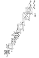
- a cuvette block is denoted 1. This has, in the chosen design, the shape of an right-angled block of aluminium, with a square cross section perpendicular to the direction of a ray path 2.
- the ray path begins in a source 3 for infrared light, concealed in the drawing, out of four such sources in total mounted on a circuit board 4. From each of the sources one ray path, not shown, runs parallel to ray path 2, which further ray path may pass through similar parts named below and have its end in similar a detector as ray path 2. These ray paths are in the corners of a square.
- an electric motor 5 is placed for rotation of a cutter wing 6 which has two diagonally opposite wing elements of phosphorus bronze with a 90° centre angle.
- the cutter wing opens in the position shown for ray path 2 and for the diagonally opposite ray path, while it breaks the other two ray paths.
- the ray path passes a focusing block shaped as an aluminium block with bores 8 for the four ray paths.
- a distance plate 9 of plastic material gives a temperature barrier between means placed before and after, and is a square slice having a circular opening 10 where the cutter wing 6 rotates.
- the cuvette block 1 has in each of its square surfaces a circular recess 10, 11, in each of which the first 12 and a second 13 cuvette window of calcium fluoride CaF 2 may be placed, to sealing contact with the bottom surface of the respective recess.
- four cuvettes 14a, 14b, 14c, 14d are placed in the respective ray path, and designed as through-going bores having their axes substantially in the respective ray path. The ends of the bores are sealed by the cuvette windows.
- two channels 15 and 16 are cut, which connect the cuvette 14a with 14b and 14c with 14d, respectively.
- a channel 17 is cut in the bottom of the recess 11 connecting the cuvette 14b with 14c.
- a pipe shaped inlet conduit 18 opens in the cuvette 14a close to the end thereof facing window 13, and close to the end of the cuvette 14d facing the same window, a pipe shaped outlet conduit 19 exits.
- the cuvette widows 12 and 13 respectively, seal the open sides of channels 15 and 16, and 17, respectively.
- a closed conduit is formed between elements 18, 14a, 15, 14b, 17, 14c, 16, 14d and 19.
- the inner diameters of the inlet and outlet conduits is 1 mm
- the diameter of the cuvettes is 2 mm
- the width of the channels parallel to the respective cuvette glass is 1 mm
- their depths are 0.5 mm
- the length of the cuvettes is 4.8 mm.
- a distance block 20 of aluminium is placed immediately after the cuvette block. This has four holes in register with the four ray paths. In the holes, four detector holders 21a, 21b, 21c, 21d fit, placed on a heating block provided with a device, not shown, for holding detectors placed thereon at a constant elevated temperature. On the holder 21a a detector 22a for infrared light is attached, covered by a filter 23a, transmitting a wavelength which can be used for determination of concentration of a gas in sample gas flow, which is let in through the inlet conduit 18. Corresponding detectors 22b, 22c, 22d, but for different wavelengths are arranged on holders 21b, 21c and 21d.
- the heating block can preferably be placed flatly against a circuit board provided with terminals for the detectors.
- a temperature insulating frame 24 of polymer foam is designed to cover the heating block, the distance block and the cuvette block, in the assembled position of the device.
- Said frame has recesses 25, 26 for conduits 18, 19.
- Four screws 27 are arranged to hold the device gas analysis together, through corresponding holes.
- the side of its square cross section may be 37 mm and the length in the direction of the ray path 32.5 mm, the motor 5 for the cutter wing not counted.
- the special cuvette block which contains four separate cuvettes with connecting channels, makes it possible to reduce the size of the gas analysis device to less than half of the corresponding previously known constructions.
- the compact design means that the light scattering between the light source and the detector is reduced to a minimum, while a sufficient length of the cuvettes is maintained for achieving sufficient absorbency.
- a device for a gas analysis can, by its small size and small consumption of power, be mounted directly on the circuit board which handles the desired measurement and control.
- IR measuring of gases for anaesthesia has required a long optical wavelength in the measuring cuvette. This is due to the fact that gases for anaesthesia have a relatively weak absorption in the wavelength field which available detectors permit.
- pyro-electric detectors which have a broader active spectrum, become more and more inexpensive.
- the pyro-electric detectors have a higher intrinsic noise than traditional lead-selenide detectors.
- the noise problems caused by the detector can be handled by filtering the measuring signal. With strong filtering, one however risks that important curve information is lost, something which is not acceptable from a clinical point of view.
- devices for a gas analysis have been provided with an adaptive digital filter realized in software.
- the adaptive filter "looks" at the measuring signal and selects a degree of filtration depending on the derivative of the curve - when the measuring signal is constant a stronger filter is selected than when the measuring signal varies.
- the chosen algorithm can comprise a number, for example five different so called finite impulse response (FIR) filter or infinite impulse response (IIR) filters, which the micro processor selects based on the appearance of the measuring signal.
- FIR finite impulse response
- IIR infinite impulse response
- Adaptive filters in software are well-known to one skilled in the field of computerized measuring technique, and is described for example by Alan V. Oppenheim and Roland W.
- the measuring signal obtained from the detectors can most closely be described as a triangle wave, the derivative of which being proportional to the radiation energy denoted I, transmitted through the measuring cuvette.
- the micro processor has to enter into and convert the measuring signal analogue-to-digital, synchronously with the same.
- the measuring value thus obtained has thereupon to be put in relation to transmitted energy of radiation through the measuring cuvette without the measured gas, denoted I 0 .
- A log(I 0 /I) ⁇ cl
- l optical wavelength the measuring cuvette
- c the concentration of the gas.
- I 0 is, apart from temperature drift etc, constant for the device for a gas analysis and is computed by the microprocessor now and then shifting the pneumatics in the instrument thus that a different gas is lead into the measuring cuvette.
- a measuring value is obtained proportional to the concentration of the gas.
- the program also has to comprise routines for calibration, compensation of pressure and other corrections.
Landscapes
- Physics & Mathematics (AREA)
- Health & Medical Sciences (AREA)
- Life Sciences & Earth Sciences (AREA)
- Chemical & Material Sciences (AREA)
- Analytical Chemistry (AREA)
- Biochemistry (AREA)
- General Health & Medical Sciences (AREA)
- General Physics & Mathematics (AREA)
- Immunology (AREA)
- Pathology (AREA)
- Investigating Or Analysing Materials By Optical Means (AREA)
- Analysing Materials By The Use Of Radiation (AREA)
- Sampling And Sample Adjustment (AREA)
Claims (10)
- Vorrichtung zur Gasanalyse zur Bestimmung des Gehalts zweier oder mehrerer Gase in einem Gasstrom, wobei die Vorrichtung wenigstens eine Emissionsquelle (3) zweier oder mehrerer Strahlenwege (2) der Strahlung einer nachweisbaren Wellenlänge, eine Küvettenvorrichtung mit einem Einlass (18) und einem Auslass (19) für den Gasstrom, ein Filter (23) zum Durchgang der Strahlung einer charakteristischen Wellenlänge für das jeweilige Gas und eine Detektorvorrichtung umfasst, die eine Vielzahl von Detektoren (22) zur Umwandlung der Strahlung in ein elektrisches Signal umfasst, dadurch gekennzeichnet, dass die Küvettenvorrichtung einen Block (1) mit einer Anzahl hindurchgehender Küvetten (14a, 14b, 14c, 14d), die von Durchbohrungen in dem Block gebildet werden, in jedem der Strahlenwege umfasst, wobei die Küvetten miteinander durch Kanäle (15, 16, 17) verbunden sind, die die Enden der Küvetten zur Bildung eines nicht unterbrochenen Leitungsrohrs für den Gasstrom von dem Einlass zu dem Auslass verbinden, und dass ein erstes (12) und ein zweites (13) Küvettenfenster, wobei die Küvettenfenster für die zu bestimmende Strahlung transparent sind, an dem Block bei jedem Ende der Küvettenvorrichtung in dem Strahlenweg von der Quelle angeordnet ist, wobei die Detektoren benachbart zu dem zweiten Küvettenfenster angeordnet sind.
- Vorrichtung zur Gasanalyse nach Anspruch 1, dadurch gekennzeichnet, dass die Verbindungskanäle (15, 16, 17) im wesentlichen senkrecht zur Richtung des Strahlenweges sind.
- Vorrichtung zur Gasanalyse nach Anspruch 2, dadurch gekennzeichnet, dass die Kanäle als Aussparungen in der Oberfläche des Küvettenblocks gemacht sind und dass jeder Kanal dadurch zusätzlich in Seitwärtsrichtung durch eines der Küvettenfenster begrenzt wird.
- Vorrichtung zur Gasanalyse nach einem oder mehreren der vorhergehenden Ansprüche, dadurch gekennzeichnet, dass die Küvetten um eine zentrale Achse in dem Küvettenblock angeordnet sind, wobei die Achse parallel zur Richtung des Strahlenweges ist.
- Vorrichtung zur Gasanalyse nach Anspruch 4, dadurch gekennzeichnet, dass die zentrale Achse mit der Rotationsachse eines Schneidflügels koaxial ist, der den Strahlenweg intermittierend unterbricht.
- Vorrichtung zur Gasanalyse nach einem oder mehreren der vorhergehenden Ansprüche, dadurch gekennzeichnet, dass die Anzahl der Küvetten vier oder ein Mehrfaches davon beträgt.
- Vorrichtung zur Gasanalyse nach einem oder mehreren der vorhergehenden Ansprüche, dadurch gekennzeichnet, dass die Detektoren pyroelektrische Detektoren sind.
- Vorrichtung zur Gasanalyse nach einem oder mehreren der vorhergehenden Ansprüche, dadurch gekennzeichnet, dass die Detektorvorrichtung eine temperaturgesteuerte Platte umfasst, auf der die Detektoren befestigt sind.
- Vorrichtung zur Gasanalyse nach einem oder mehreren der vorhergehenden Ansprüche, dadurch gekennzeichnet, dass die Filter zum Durchgang der Strahlung einer charakteristischen Wellenlänge an dem jeweiligen Detektor befestigt sind.
- Vorrichtung zur Gasanalyse nach einem oder mehreren der vorhergehenden Ansprüche, dadurch gekennzeichnet, dass sie eine Signalverarbeitungseinrichtung umfasst, worin die Signale durch Software gefiltert werden und die Filtration adaptiv erfolgt, bezogen das Auftreten des Messsignals.
Applications Claiming Priority (2)
| Application Number | Priority Date | Filing Date | Title |
|---|---|---|---|
| SE9200023 | 1992-01-03 | ||
| SE9200023A SE9200023L (sv) | 1992-01-03 | 1992-01-03 | Gasanalysator |
Publications (3)
| Publication Number | Publication Date |
|---|---|
| EP0550396A2 EP0550396A2 (de) | 1993-07-07 |
| EP0550396A3 EP0550396A3 (en) | 1994-08-17 |
| EP0550396B1 true EP0550396B1 (de) | 2002-03-13 |
Family
ID=20384961
Family Applications (1)
| Application Number | Title | Priority Date | Filing Date |
|---|---|---|---|
| EP92850310A Expired - Lifetime EP0550396B1 (de) | 1992-01-03 | 1992-12-23 | Gasanalysegerät |
Country Status (5)
| Country | Link |
|---|---|
| US (1) | US5326973A (de) |
| EP (1) | EP0550396B1 (de) |
| AT (1) | ATE214480T1 (de) |
| DE (1) | DE69232482T2 (de) |
| SE (1) | SE9200023L (de) |
Families Citing this family (33)
| Publication number | Priority date | Publication date | Assignee | Title |
|---|---|---|---|---|
| US5545897A (en) * | 1994-10-04 | 1996-08-13 | Santa Barbara Research Center | Optically-based chemical detection system |
| US5757482A (en) * | 1995-04-20 | 1998-05-26 | Perseptive Biosystems, Inc. | Module for optical detection in microscale fluidic analyses |
| US6309360B1 (en) | 1997-03-17 | 2001-10-30 | James R. Mault | Respiratory calorimeter |
| US6572561B2 (en) | 1998-01-16 | 2003-06-03 | Healthetech, Inc. | Respiratory calorimeter |
| CA2320238C (en) | 1998-02-05 | 2011-08-23 | James R. Mault | Metabolic calorimeter employing respiratory gas analysis |
| US5931161A (en) * | 1998-03-18 | 1999-08-03 | Datex-Ohmeda, Inc. | On-airway respiratory gas monitor employing transformed infrared signals |
| AU5392499A (en) | 1998-08-03 | 2000-02-28 | James R. Mault | Method and apparatus for respiratory gas analysis employing measurement of expired gas mass |
| US6406435B1 (en) | 1998-11-17 | 2002-06-18 | James R. Mault | Method and apparatus for the non-invasive determination of cardiac output |
| CA2372658A1 (en) | 1999-05-10 | 2000-11-16 | James R. Mault | Airway-based cardiac output monitor and methods for using same |
| US6468222B1 (en) | 1999-08-02 | 2002-10-22 | Healthetech, Inc. | Metabolic calorimeter employing respiratory gas analysis |
| US6899684B2 (en) * | 1999-08-02 | 2005-05-31 | Healthetech, Inc. | Method of respiratory gas analysis using a metabolic calorimeter |
| EP1217942A1 (de) | 1999-09-24 | 2002-07-03 | Healthetech, Inc. | Physiologisches überwachungsgerät und damit verbundener computer, anzeigegerät und kommunikationseinheit |
| US6478736B1 (en) | 1999-10-08 | 2002-11-12 | Healthetech, Inc. | Integrated calorie management system |
| US6612306B1 (en) | 1999-10-13 | 2003-09-02 | Healthetech, Inc. | Respiratory nitric oxide meter |
| US6629934B2 (en) | 2000-02-02 | 2003-10-07 | Healthetech, Inc. | Indirect calorimeter for medical applications |
| US6482158B2 (en) | 2000-05-19 | 2002-11-19 | Healthetech, Inc. | System and method of ultrasonic mammography |
| US20030208133A1 (en) * | 2000-06-07 | 2003-11-06 | Mault James R | Breath ketone analyzer |
| CA2413657A1 (en) | 2000-06-16 | 2001-12-20 | Healthetech, Inc. | Speech recognition capability for a personal digital assistant |
| US6620106B2 (en) | 2000-09-29 | 2003-09-16 | Healthetech, Inc. | Indirect calorimetry system |
| US6607387B2 (en) | 2000-10-30 | 2003-08-19 | Healthetech, Inc. | Sensor system for diagnosing dental conditions |
| US20020138213A1 (en) * | 2001-03-02 | 2002-09-26 | Mault James R. | System and method of metabolic rate measurement |
| US20030023181A1 (en) * | 2001-07-26 | 2003-01-30 | Mault James R. | Gas analyzer of the fluorescent-film type particularly useful for respiratory analysis |
| AU2003223420A1 (en) * | 2002-04-01 | 2003-10-20 | Healthetech, Inc. | System and method of determining an individualized drug administration dosage |
| GB2389177B (en) * | 2002-05-31 | 2006-03-15 | Marconi Applied Techn Ltd | Gas sensors |
| USD478660S1 (en) | 2002-07-01 | 2003-08-19 | Healthetech, Inc. | Disposable mask with sanitation insert for a respiratory analyzer |
| GB2395259A (en) * | 2002-11-07 | 2004-05-19 | E2V Tech Uk Ltd | Gas sensor with predetermined optical paths between its different detectors |
| GB2395260B (en) * | 2002-11-07 | 2005-11-02 | E2V Tech Uk Ltd | Gas sensors |
| DE102006019705B3 (de) * | 2006-04-27 | 2007-06-14 | Tyco Electronics Raychem Gmbh | Dynamisches Messwertfilter für eine Gassensoranordnung |
| DE102008005572B4 (de) * | 2008-01-22 | 2011-04-14 | Smartgas Mikrosensorik Gmbh | Messverfahren und Gassensor zur simultanen Erfassung der Konzentration zweier unterschiedlicher Gase |
| US7880887B2 (en) * | 2008-08-29 | 2011-02-01 | Phygen, Inc. | Apparatus and method for measuring the concentration of gases in a sterilization chamber |
| CN103217506B (zh) * | 2012-01-19 | 2016-03-23 | 深圳迈瑞生物医疗电子股份有限公司 | 一种气体监测医疗设备 |
| US20220291116A1 (en) * | 2019-08-29 | 2022-09-15 | Kyocera Corporation | Gas supply and discharge adapter and gas detection device |
| WO2025017944A1 (ja) * | 2023-07-20 | 2025-01-23 | 荏原実業株式会社 | 測定セルおよび光学分析装置 |
Family Cites Families (10)
| Publication number | Priority date | Publication date | Assignee | Title |
|---|---|---|---|---|
| US3743426A (en) * | 1971-11-26 | 1973-07-03 | Gen Motors Corp | Multichannel exhaust gas analyzer |
| DE2707090A1 (de) * | 1977-02-18 | 1978-08-24 | Siemens Ag | Gasanalysator |
| US4370553A (en) * | 1980-07-02 | 1983-01-25 | Sensors, Inc. | Contaminated sample gas analyzer and gas cell therefor |
| DE3030002A1 (de) * | 1980-08-08 | 1982-03-11 | Hartmann & Braun Ag, 6000 Frankfurt | Nichtdispersiver infrarot-gasanalysator |
| DE3208737A1 (de) * | 1982-03-11 | 1983-09-22 | Drägerwerk AG, 2400 Lübeck | Optisches mehrstrahl-gasmessgeraet |
| US4817013A (en) * | 1986-10-17 | 1989-03-28 | Nellcor, Inc. | Multichannel gas analyzer and method of use |
| SE459126B (sv) * | 1987-09-15 | 1989-06-05 | Gambro Engstrom Ab | Optisk gasanalysator |
| US5060508A (en) * | 1990-04-02 | 1991-10-29 | Gaztech Corporation | Gas sample chamber |
| WO1992015860A1 (en) * | 1991-03-08 | 1992-09-17 | Axiom Analytical Corporation | Gas sample analysis provided by light pipe radiation structure |
| US5218428A (en) * | 1991-10-08 | 1993-06-08 | The Perkin-Elmer Corporation | Optical transmittance apparatus for fluids |
-
1992
- 1992-01-03 SE SE9200023A patent/SE9200023L/ not_active IP Right Cessation
- 1992-12-23 AT AT92850310T patent/ATE214480T1/de not_active IP Right Cessation
- 1992-12-23 DE DE69232482T patent/DE69232482T2/de not_active Expired - Fee Related
- 1992-12-23 EP EP92850310A patent/EP0550396B1/de not_active Expired - Lifetime
- 1992-12-31 US US07/999,203 patent/US5326973A/en not_active Expired - Lifetime
Also Published As
| Publication number | Publication date |
|---|---|
| ATE214480T1 (de) | 2002-03-15 |
| SE468782B (sv) | 1993-03-15 |
| US5326973A (en) | 1994-07-05 |
| DE69232482D1 (de) | 2002-04-18 |
| EP0550396A3 (en) | 1994-08-17 |
| SE9200023D0 (sv) | 1992-01-03 |
| DE69232482T2 (de) | 2002-11-07 |
| EP0550396A2 (de) | 1993-07-07 |
| SE9200023L (sv) | 1993-03-15 |
Similar Documents
| Publication | Publication Date | Title |
|---|---|---|
| EP0550396B1 (de) | Gasanalysegerät | |
| US5932877A (en) | High performance side stream infrared gas analyzer | |
| JP4729215B2 (ja) | 同位体比率を測定するための赤外分光計 | |
| RU2476148C2 (ru) | Метаболическая измерительная система с многофункциональным адаптером для дыхательных путей | |
| US4041932A (en) | Method for monitoring blood gas tension and pH from outside the body | |
| US8080798B2 (en) | Gas measurement system | |
| US7432508B2 (en) | Gas measurement system | |
| US5468961A (en) | Infrared gas analyser and humidity sensor | |
| EP0289581B1 (de) | Mehrkanalgas-analysierungsgerät und verwendung | |
| US6612306B1 (en) | Respiratory nitric oxide meter | |
| CA1301474C (en) | Sensor for measuring the concentration of a gaseous component in a fluid absorption | |
| US6144444A (en) | Apparatus and method to determine blood parameters | |
| US7235054B2 (en) | Measuring head for a gas analyser | |
| EP0307625A2 (de) | Optisches Gasanalysegerät | |
| US20030065273A1 (en) | Metabolic calorimeter employing respiratory gas analysis | |
| EP0210417A1 (de) | Verfahren und Gerät zur Bestimmung von Blutbestandteilen | |
| JPH05509026A (ja) | 可処分気道アダプタ | |
| CA2379188A1 (en) | Metabolic calorimeter employing respiratory gas analysis | |
| JPH05507866A (ja) | 生体内の血糖レベルを測定するための装置 | |
| WO1993009711A1 (en) | Using led harmonic wavelengths for near-infrared quantitative measurements | |
| EP1112716B1 (de) | Kostengünstiges System mit einem Hauptstromgasanalysator | |
| US20040065835A1 (en) | Low volume sample cell and gas monitoring system using same | |
| US7701581B2 (en) | Device for determining of properties in a fluid and/or constituents thereof | |
| WO2007103855A2 (en) | Gas measurement system | |
| EP0980518B1 (de) | VORRICHTUNG ZUR BESTIMMUNG VON pH, pCO2, HÄMOGLOBIN UND HÄMOGLOBIN-SAUERSTOFFSÄTTIGUNG |
Legal Events
| Date | Code | Title | Description |
|---|---|---|---|
| PUAI | Public reference made under article 153(3) epc to a published international application that has entered the european phase |
Free format text: ORIGINAL CODE: 0009012 |
|
| AK | Designated contracting states |
Kind code of ref document: A2 Designated state(s): AT BE CH DE DK ES FR GB GR IE IT LI LU MC NL PT SE |
|
| PUAL | Search report despatched |
Free format text: ORIGINAL CODE: 0009013 |
|
| AK | Designated contracting states |
Kind code of ref document: A3 Designated state(s): AT BE CH DE DK ES FR GB GR IE IT LI LU MC NL PT SE |
|
| 17P | Request for examination filed |
Effective date: 19950316 |
|
| 17Q | First examination report despatched |
Effective date: 19990212 |
|
| GRAG | Despatch of communication of intention to grant |
Free format text: ORIGINAL CODE: EPIDOS AGRA |
|
| GRAG | Despatch of communication of intention to grant |
Free format text: ORIGINAL CODE: EPIDOS AGRA |
|
| GRAH | Despatch of communication of intention to grant a patent |
Free format text: ORIGINAL CODE: EPIDOS IGRA |
|
| GRAH | Despatch of communication of intention to grant a patent |
Free format text: ORIGINAL CODE: EPIDOS IGRA |
|
| REG | Reference to a national code |
Ref country code: GB Ref legal event code: IF02 |
|
| GRAA | (expected) grant |
Free format text: ORIGINAL CODE: 0009210 |
|
| AK | Designated contracting states |
Kind code of ref document: B1 Designated state(s): AT BE CH DE DK ES FR GB GR IE IT LI LU MC NL PT SE |
|
| PG25 | Lapsed in a contracting state [announced via postgrant information from national office to epo] |
Ref country code: NL Free format text: LAPSE BECAUSE OF FAILURE TO SUBMIT A TRANSLATION OF THE DESCRIPTION OR TO PAY THE FEE WITHIN THE PRESCRIBED TIME-LIMIT Effective date: 20020313 Ref country code: LI Free format text: LAPSE BECAUSE OF FAILURE TO SUBMIT A TRANSLATION OF THE DESCRIPTION OR TO PAY THE FEE WITHIN THE PRESCRIBED TIME-LIMIT Effective date: 20020313 Ref country code: IT Free format text: LAPSE BECAUSE OF FAILURE TO SUBMIT A TRANSLATION OF THE DESCRIPTION OR TO PAY THE FEE WITHIN THE PRESCRIBED TIME-LIMIT;WARNING: LAPSES OF ITALIAN PATENTS WITH EFFECTIVE DATE BEFORE 2007 MAY HAVE OCCURRED AT ANY TIME BEFORE 2007. THE CORRECT EFFECTIVE DATE MAY BE DIFFERENT FROM THE ONE RECORDED. Effective date: 20020313 Ref country code: GR Free format text: LAPSE BECAUSE OF FAILURE TO SUBMIT A TRANSLATION OF THE DESCRIPTION OR TO PAY THE FEE WITHIN THE PRESCRIBED TIME-LIMIT Effective date: 20020313 Ref country code: CH Free format text: LAPSE BECAUSE OF FAILURE TO SUBMIT A TRANSLATION OF THE DESCRIPTION OR TO PAY THE FEE WITHIN THE PRESCRIBED TIME-LIMIT Effective date: 20020313 Ref country code: BE Free format text: LAPSE BECAUSE OF FAILURE TO SUBMIT A TRANSLATION OF THE DESCRIPTION OR TO PAY THE FEE WITHIN THE PRESCRIBED TIME-LIMIT Effective date: 20020313 Ref country code: AT Free format text: LAPSE BECAUSE OF FAILURE TO SUBMIT A TRANSLATION OF THE DESCRIPTION OR TO PAY THE FEE WITHIN THE PRESCRIBED TIME-LIMIT Effective date: 20020313 |
|
| REF | Corresponds to: |
Ref document number: 214480 Country of ref document: AT Date of ref document: 20020315 Kind code of ref document: T |
|
| REG | Reference to a national code |
Ref country code: CH Ref legal event code: EP |
|
| REF | Corresponds to: |
Ref document number: 69232482 Country of ref document: DE Date of ref document: 20020418 |
|
| PG25 | Lapsed in a contracting state [announced via postgrant information from national office to epo] |
Ref country code: SE Free format text: LAPSE BECAUSE OF FAILURE TO SUBMIT A TRANSLATION OF THE DESCRIPTION OR TO PAY THE FEE WITHIN THE PRESCRIBED TIME-LIMIT Effective date: 20020613 Ref country code: DK Free format text: LAPSE BECAUSE OF FAILURE TO SUBMIT A TRANSLATION OF THE DESCRIPTION OR TO PAY THE FEE WITHIN THE PRESCRIBED TIME-LIMIT Effective date: 20020613 |
|
| PG25 | Lapsed in a contracting state [announced via postgrant information from national office to epo] |
Ref country code: PT Free format text: LAPSE BECAUSE OF FAILURE TO SUBMIT A TRANSLATION OF THE DESCRIPTION OR TO PAY THE FEE WITHIN THE PRESCRIBED TIME-LIMIT Effective date: 20020614 |
|
| NLV1 | Nl: lapsed or annulled due to failure to fulfill the requirements of art. 29p and 29m of the patents act | ||
| ET | Fr: translation filed | ||
| REG | Reference to a national code |
Ref country code: CH Ref legal event code: PL |
|
| PG25 | Lapsed in a contracting state [announced via postgrant information from national office to epo] |
Ref country code: ES Free format text: LAPSE BECAUSE OF FAILURE TO SUBMIT A TRANSLATION OF THE DESCRIPTION OR TO PAY THE FEE WITHIN THE PRESCRIBED TIME-LIMIT Effective date: 20020925 |
|
| PGFP | Annual fee paid to national office [announced via postgrant information from national office to epo] |
Ref country code: GB Payment date: 20021204 Year of fee payment: 11 |
|
| PG25 | Lapsed in a contracting state [announced via postgrant information from national office to epo] |
Ref country code: LU Free format text: LAPSE BECAUSE OF NON-PAYMENT OF DUE FEES Effective date: 20021223 Ref country code: IE Free format text: LAPSE BECAUSE OF NON-PAYMENT OF DUE FEES Effective date: 20021223 |
|
| PGFP | Annual fee paid to national office [announced via postgrant information from national office to epo] |
Ref country code: DE Payment date: 20021223 Year of fee payment: 11 |
|
| PLBE | No opposition filed within time limit |
Free format text: ORIGINAL CODE: 0009261 |
|
| 26N | No opposition filed |
Effective date: 20021216 |
|
| PG25 | Lapsed in a contracting state [announced via postgrant information from national office to epo] |
Ref country code: MC Free format text: LAPSE BECAUSE OF NON-PAYMENT OF DUE FEES Effective date: 20030701 |
|
| REG | Reference to a national code |
Ref country code: IE Ref legal event code: MM4A |
|
| PGFP | Annual fee paid to national office [announced via postgrant information from national office to epo] |
Ref country code: FR Payment date: 20031128 Year of fee payment: 12 |
|
| PG25 | Lapsed in a contracting state [announced via postgrant information from national office to epo] |
Ref country code: GB Free format text: LAPSE BECAUSE OF NON-PAYMENT OF DUE FEES Effective date: 20031223 |
|
| PG25 | Lapsed in a contracting state [announced via postgrant information from national office to epo] |
Ref country code: DE Free format text: LAPSE BECAUSE OF NON-PAYMENT OF DUE FEES Effective date: 20040701 |
|
| GBPC | Gb: european patent ceased through non-payment of renewal fee |
Effective date: 20031223 |
|
| PG25 | Lapsed in a contracting state [announced via postgrant information from national office to epo] |
Ref country code: FR Free format text: LAPSE BECAUSE OF NON-PAYMENT OF DUE FEES Effective date: 20050831 |
|
| REG | Reference to a national code |
Ref country code: FR Ref legal event code: ST |