EP0550251A2 - Circular knitting machine - Google Patents
Circular knitting machine Download PDFInfo
- Publication number
- EP0550251A2 EP0550251A2 EP92311732A EP92311732A EP0550251A2 EP 0550251 A2 EP0550251 A2 EP 0550251A2 EP 92311732 A EP92311732 A EP 92311732A EP 92311732 A EP92311732 A EP 92311732A EP 0550251 A2 EP0550251 A2 EP 0550251A2
- Authority
- EP
- European Patent Office
- Prior art keywords
- guiding
- cam
- butts
- needles
- knitting
- Prior art date
- Legal status (The legal status is an assumption and is not a legal conclusion. Google has not performed a legal analysis and makes no representation as to the accuracy of the status listed.)
- Granted
Links
Images

Classifications
-
- D—TEXTILES; PAPER
- D04—BRAIDING; LACE-MAKING; KNITTING; TRIMMINGS; NON-WOVEN FABRICS
- D04B—KNITTING
- D04B15/00—Details of, or auxiliary devices incorporated in, weft knitting machines, restricted to machines of this kind
- D04B15/66—Devices for determining or controlling patterns ; Programme-control arrangements
- D04B15/82—Devices for determining or controlling patterns ; Programme-control arrangements characterised by the needle cams used
Definitions
- the invention relates to circular knitting machines, especially machines for manufacturing hosiery or the like, provided with latch needles mounted in a needle cylinder.
- the needles are lowered and lifted by means of swinging sinkers which are provided with two guiding butts alternately engageable with cam channels.
- the butts can be provided immediately on the needles, or on guiding sinkers of double-head needles.
- Circular knitting machines provided with above-mentioned swinging sinkers having each two guiding butts, are well known. Such machines are adapted for reverse knitting operations, such as knitting heels and toes of hosiery, and particularly in a single feed system.
- the system is usually provided with a right-hand and left-hand sinking cam as well as with a heel cam the latter being designed for displacing the needles to the level of the above-mentioned sinking cams, i.e. in both knitting directions. Due to such an arrangement, the cam channels for butts of needles or of needle guiding sinkers cross each other.
- a compensating cam which is designed for preventing the needles from assuming, owing to the knitting speed, a position which is lower than that which is suitable for laying thread into the needles. Consequently, the needle races are broken, and the guiding butts are exposed, during their motion, to many shocks so that their paths lose the curvilinear course. Apart from this, this motion, especially with double-cylinder machines, is ensured, within a race section, by upper butts while within another race section, by lower butts of guiding sinkers so that even the race continuity is impaired. In this case any increase of knitting speed is therefore difficult.
- At least one first sinking cam for the rotational knitting direction, is provided in the cam channel for first guiding butts while in the cam channel for second guiding butts there is provided at least one second sinking cam or at least one third sinking cam for the reverse knitting direction.
- Cam means are provided in the cam channel of the second guiding butts for transferring needles from knitting paths into an elevated heel path and vice versa, said means comprising especially three shaped through-grooves having at their ends chamferings for forcing the second guiding butts into vertical tricks of the needle cylinder.
- each shaped through-groove Above the starting point of each shaped through-groove is provided a swinging push-button while in the cam channel for the first guiding butts are provided means for reducing and adding needles in case of the reverse knitting operation, said means comprising especially a shaped through-groove having at its end a chamfering for forcing the first guiding butts into the vertical tricks of the needle cylinder, a radially movable push-button being provided above the starting point of said shaped through-groove.
- the cam channels for guiding the first and the second guiding butts are separate from each other for the two knitting directions.
- a double-cylinder circular knitting machine designed for manufacturing ribbed goods and links-links hosiery, comprises an upper needle cylinder (not shown) and a lower needle cylinder 1.
- Vertical tricks 2 of said lower needle cylinder 1 receive guiding sinkers 3 of needles 4'.
- the needles 4' are of a double-head latch type which allows transfer to the upper needle cylinder for knitting links-links stitches.
- each guiding sinker 3 carries a swinging sinker 4 having one first and one second guiding butt 41 and 42, respectively, as well as pattern butts 43.
- the cam system of the lower needle cylinder 1 comprises five cam sections 5, 6, 7, 8 and 9.
- a first sinking cam 10 for engaging the needle 4' in the rotational knitting direction S.
- a second vertically movable sinking cam 11 is provided for engaging the needles 4' in the rotational knitting direction S.
- a third sinking cam 12 for engaging the needles 4' in the reverse knitting direction S'.
- a shaped through-groove 14' serves for guiding the first guiding butts 41 in the reverse knitting direction S' and terminates in a chamfering 141' for forcing the first guiding butts 41 into the vertical tricks 2 of the lower needle cylinder 1.
- In the cam section 7 are provided three shaped through-grooves 71, 72 and 73, and particularly in the path of the second guiding butts 42.
- the groove 71 is designed for transferring the needles 4' from the knitting position into the heel position during the reverse direction S' of rotation.
- the starting point of the groove 71 corresponds to the clearing position of the needle 4', and the end portion to the heel position.
- the groove 71 has a chamfering 711 for forcing the second guiding butts 42 into the vertical tricks 2 of the needle cylinder 1.
- the shaped through-groove 72 serves for transferring the needles 4' from the heel position back to the knitting one during the reverse knitting direction S', the starting point of the groove 72 corresponding to the heel position of the needle 4' and the end portion to the clearing position.
- the end portion of the groove 72 has also a chamfering 722 for forcing the second guiding butts 42.
- the third shaped through-groove 73 is a mirror image of the groove 72 and serves for the same purpose. At the end of said groove 73 there is also a chamfering 733 for forcing the second guiding butts 42.
- the cam sections 8, 9 and 7 form in common a channel 15 for guiding the second guiding butts 42 to a height corresponding to that for guiding empty guiding sinkers 3 when their points open the latches of upper needles 4'; alternatively, said channel 15 can serve for transferring the needles 4' between the two needle cylinders.
- the cam sections 8 and 9 form a channel 16 within the path of the second guiding butts 42 for the stitch-forming motion of needles 4' in the second knitting system during the rotational knitting direction S, one part of said channel 16 being provided still in the cam section 9.
- a shaped through-groove 91 which is a mirror image of the groove 71, including chamfering 911 of the groove 91, so that the latter serves for reducing the needle number for the rotational knitting direction S.
- a shaped through-groove 92 giving the needles 4' the stitch-forming motion in the reverse knitting direction S' and partially also in the rotational knitting direction S, the groove 92 terminating at its ends in chamferings 921 and 922 designed for forcing the second guiding butts 42.
- a through-groove for a push-button 17.
- each of said push-buttons 20, 21, 22 and 23 comprises a swinging presser lever 24 ( Figure 3) spring-loaded by a torsion spring provided about its pivot.
- the swinging presser level 24 is arranged on a carrier 25 fixedly supporting a permanent magnet 26 together with a coil 27 connected to a machine controlling computer.
- the carrier 25 can be approached to the lower needle cylinder 1.
- the swinging push-buttons 20 to 23 are situated within the path of the second guiding butts 42 in the channel 14 so that they engage the guiding butts 41 in front of the choice point V.
- the guiding levers of the guiding means exert, according to a programme, a pressure to the pattern butts 43 so that the swinging sinkers 4 follow by their first guiding butts 41 the path of the channel 14 so that the guiding sinkers 3 and the corresponding needles 4' form then, in the first knitting system or on the first sinking cam 10, respectively, face stitches of the fabric .
- the first guiding butts 41 are forced into the lower needle cylinder 1 while the second guiding butts 42 are swung into the channel 16, and said needles 4' form face stitches in the second knitting system or on the second sinking cam 11 whereupon the guiding sinkers 3 are displaced again to the position in front of the choice point V or of the radially movable push-button 19.
- the swinging sinkers 4 whose pattern butts 43 have not been forced into the needle cylinder 1, are guided, by means of their second guiding butts 42, in the channel 15.
- both empty and guiding sinkers 3 together with needles 4' are disengaged so that the needles 4' are transferred between the two needle cylinders, provided the needles in the upper needle cylinder are also brought into the transfer position.
- the empty guiding sinkers 3 pass then by means of the first guiding butts 41 through the channel 15 up the choice point V.
- the needles 4' once transferred onto the upper needle cylinder, form there back stitches.
- the heel or the toe of a hose is formed by the reverse motion of the needle cylinders in the following way:
- the needles 4' are separated in the lower needle cylinder into operating and inoperating ones; also the guiding sinkers 3 are separated in this way.
- the selecting device all the pattern butts 43 are pressed in.
- the radially movable push-button 24' is brought to the lower needle cylinder 1 in that section only which corresponds to the heel-forming needles 4'.
- the radially movable push-button 24' will press in the first guiding butts 41 so that second guiding butts 42 get into the shaped through-groove 91 where they are raised by the latter and pressed in again by the chamfering 911 whereby the first guiding butts 41 are received by the channel 13, and the corresponding guiding sinkers 3 or needles 4', respectively, assume an elevated heel position with stitches on the needle stems below the needle latches.
- the other needles 4' knit in the first knitting regime or system while the radially movable or approaching pushbuttons 19 and 19' are removed from the lower needle cylinder 1 whereby the second knitting system is set out of operation.
- the machine is given the reverse motion, and the swinging push-buttons 20 and 21 are brought to the lower needle cylinder 1.
- the operating needles 4' are in the clearing position, which means that the first guiding butts 41 are in the channel 14 and, still before changing the rotational knitting direction S into the reverse knitting direction S', there is effected the first stitch reducing or narrowing phase by means of the swinging push-button 21 which can force only one first guiding butt 41.
- the swinging push-button 21 or 20, respectively, operates in such way that the first guiding butt 41, owing to friction, carries along the swinging presser lever 24 which swings into a space between the adjacent first guiding butt 41 so that the next first guiding butt 41 swings up to the zone of action of the permanent magnet 26 which will attract it whereas the further first guiding butts 41 are allowed to pass and are pressed-in in the further narrowing phases.
- the swinging presser lever 24 of the swinging push-button 20 is held by the permanent magnet 26.
- the corresponding second guiding butt 42 is pressed out into the shaped through-groove 91 while, during further rotation, it strikes the chamfering 911 whereby the first guiding butts 41 is tilted out backward but into the channel 13, i.e. to the inoperative height.
- the corresponding guiding sinker 3 and the needle 4' are displaced into the heel-forming position.
- the swinging presser lever 24 of the swinging push-button 20 is held by the permanent magnet 26. If the rotational direction is changed to the reverse one S', the first guiding butts 41 are led through the channel 14 up to the shaped through-groove 14' where they are pressed in by the chamfering 141'.
- the second guiding butts 42 of the swinging sinkers 4 are tilted out into the shaped through-groove 92, and the corresponding needles 4' form stitches in the first knitting system in the reverse knitting direction S' on the third sinking cam 12. After the stitch formations the needles 4' are raised into the clearing position while the chamfering 921 will press in the second guiding butts 42 into the vertical tricks 2, and the first guiding butts 41 enter the channel 14.
- the group of operating needles 4' is then led by means of the channel 14 up to the dead point while before the latter the needle 4' or the guiding sinker 3, respectively, is eliminated from this group into the heel-forming position by the swinging push-button 20, and particularly in the same way as described with the swinging push-button 21, which means by the shaped through-groove 71 and the chamfering 711.
- a part of the first guiding butts 41 belonging to the corresponding operating needles 4', upstream of the dead point, is led again through the shaped through-groove 14' and is pressed in by the chamfering 141', and further on the guiding sinkers 3 are led up to the dead point by the second guiding butts 42 in the shaped through-groove 92.
- the swinging push-buttons 22 and 23 are set in operation; these, however, are shaped so that their swinging presser levers have a larger working front whereby they gradually press in the two first guiding butts 41. Otherwise their function remains the same. These swinging butts 22 and 23 alternately press in the first guiding butts 41 from both sides of the group of swinging sinkers 4 belonging to the guiding sinkers 3 or to the needles 4', respectively, in the elevated heel-forming position.
- the second guiding butts 42 are tilted out into the shaped through-grooves 72 or 73, respectively, and are pressed in again by the chamferings 722 and 733 so that their first guiding butts 41 are tilted out again into the channel 14, and the needles 4' are transferred in this way back to the knitting position.
- the swinging push-buttons 20 and 21 are in operation, which results again in adding only one needle 4' in each of the two knitting directions. After the needle adding has been ended, said swinging push-buttons 20 to 23 are displaced away from the lower needle cylinder 1, and the knitting machine continues its rotational operation as explained above.
- swinging sinkers 4 immediately on the needle stems in case of the single-cylinder knitting machines manufacturing hosiery with reverse heel or toe, respectively, or with single-cylinder machines for creating the so-called intarsia designs on calf by means of reverse knitting, without affecting the subject-matter of the invention.
- the invention can be applied to a machine with a plurality of knitting systems operating either in the reverse or rotational regime.
- the sinking cams of the knitting systems in the rotational operation can be provided only within the path of one type of guiding butts, which is preferable with single-cylinder machines, or in the paths of both guiding butt types, depending upon the possibilities of other knitting technologies applicable on the machine.
- the sinking cams for the rotational and the reverse direction of knitting S and S', respectively are always disposed in the grooves of the first and the second guiding butts 41 and 42, respectively.
Abstract
Description
- The invention relates to circular knitting machines, especially machines for manufacturing hosiery or the like, provided with latch needles mounted in a needle cylinder. In operation, the needles are lowered and lifted by means of swinging sinkers which are provided with two guiding butts alternately engageable with cam channels. Alternatively, the butts can be provided immediately on the needles, or on guiding sinkers of double-head needles.
- Circular knitting machines provided with above-mentioned swinging sinkers having each two guiding butts, are well known. Such machines are adapted for reverse knitting operations, such as knitting heels and toes of hosiery, and particularly in a single feed system. The system is usually provided with a right-hand and left-hand sinking cam as well as with a heel cam the latter being designed for displacing the needles to the level of the above-mentioned sinking cams, i.e. in both knitting directions. Due to such an arrangement, the cam channels for butts of needles or of needle guiding sinkers cross each other. Below the heel cam there is provided a compensating cam which is designed for preventing the needles from assuming, owing to the knitting speed, a position which is lower than that which is suitable for laying thread into the needles. Consequently, the needle races are broken, and the guiding butts are exposed, during their motion, to many shocks so that their paths lose the curvilinear course. Apart from this, this motion, especially with double-cylinder machines, is ensured, within a race section, by upper butts while within another race section, by lower butts of guiding sinkers so that even the race continuity is impaired. In this case any increase of knitting speed is therefore difficult.
- It is an object of the present invention to eliminate the drawbacks of prior art as hereinabove referred to and to provide an improved circular knitting machine, especially for manufacturing hosiery, provided with latch needles which are mounted in the lower needle cylinder and which, in operation, are lowered and lifted by swinging sinkers provided with two guiding butts which are alternately engageable with cam channels and which can be provided either directly on the needles, or on the swinging sinkers received in vertical tricks of the lower needle cylinder.
- According to the invention, at least one first sinking cam, for the rotational knitting direction, is provided in the cam channel for first guiding butts while in the cam channel for second guiding butts there is provided at least one second sinking cam or at least one third sinking cam for the reverse knitting direction. Cam means are provided in the cam channel of the second guiding butts for transferring needles from knitting paths into an elevated heel path and vice versa, said means comprising especially three shaped through-grooves having at their ends chamferings for forcing the second guiding butts into vertical tricks of the needle cylinder. Above the starting point of each shaped through-groove is provided a swinging push-button while in the cam channel for the first guiding butts are provided means for reducing and adding needles in case of the reverse knitting operation, said means comprising especially a shaped through-groove having at its end a chamfering for forcing the first guiding butts into the vertical tricks of the needle cylinder, a radially movable push-button being provided above the starting point of said shaped through-groove. The cam channels for guiding the first and the second guiding butts are separate from each other for the two knitting directions.
- In order that the present invention be better understood and carried into practice, some preferred embodiments thereof will hereinafter be described with reference to the accompanying diagrammatic drawings, wherein:
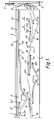
- Figure 1 shows a lower needle cylinder together with guiding butts and swinging butts;
- Figure 2 is a sectional view of the cam block, indicating the co-operation of the swinging sinker together with the push-button; and
- Figure 3 is a detail showing the swinging push-button for reducing (narrowing) or adding, respectively.
- As can be seen in the drawings, a double-cylinder circular knitting machine designed for manufacturing ribbed goods and links-links hosiery, comprises an upper needle cylinder (not shown) and a lower needle cylinder 1. Vertical tricks 2 of said lower needle cylinder 1 receive guiding
sinkers 3 of needles 4'. The needles 4' are of a double-head latch type which allows transfer to the upper needle cylinder for knitting links-links stitches. By means of ajoint 31, each guidingsinker 3 carries aswinging sinker 4 having one first and one second guidingbutt cam sections cam section 6 is mounted for vertical motion afirst sinking cam 10 for engaging the needle 4' in the rotational knitting direction S. In the cam section 8 a second verticallymovable sinking cam 11 is provided for engaging the needles 4' in the rotational knitting direction S. Finally, in thecam section 9 there is disposed athird sinking cam 12 for engaging the needles 4' in the reverse knitting direction S'. - The
cam sections channel 13 for the first guidingbutts 41 of theswinging sinkers 4, thechannel 13 constituting the work race for the needles 4' of the first knitting system for forming stitches in the rotational knitting direction S. A shaped through-groove 14' serves for guiding the first guidingbutts 41 in the reverse knitting direction S' and terminates in a chamfering 141' for forcing the first guidingbutts 41 into the vertical tricks 2 of the lower needle cylinder 1. In thecam section 7 are provided three shaped through-grooves 71, 72 and 73, and particularly in the path of the second guidingbutts 42. The groove 71 is designed for transferring the needles 4' from the knitting position into the heel position during the reverse direction S' of rotation. The starting point of the groove 71 corresponds to the clearing position of the needle 4', and the end portion to the heel position. At its end the groove 71 has a chamfering 711 for forcing the second guidingbutts 42 into the vertical tricks 2 of the needle cylinder 1. The shaped through-groove 72 serves for transferring the needles 4' from the heel position back to the knitting one during the reverse knitting direction S', the starting point of thegroove 72 corresponding to the heel position of the needle 4' and the end portion to the clearing position. The end portion of thegroove 72 has also achamfering 722 for forcing the second guidingbutts 42. Finally, the third shaped through-groove 73 is a mirror image of thegroove 72 and serves for the same purpose. At the end of said groove 73 there is also achamfering 733 for forcing the second guidingbutts 42. - The
cam sections channel 15 for guiding the second guidingbutts 42 to a height corresponding to that for guiding empty guidingsinkers 3 when their points open the latches of upper needles 4'; alternatively, saidchannel 15 can serve for transferring the needles 4' between the two needle cylinders. - The
cam sections channel 16 within the path of the second guidingbutts 42 for the stitch-forming motion of needles 4' in the second knitting system during the rotational knitting direction S, one part of saidchannel 16 being provided still in thecam section 9. In thecam section 9 is formed a shaped through-groove 91 which is a mirror image of the groove 71, including chamfering 911 of the groove 91, so that the latter serves for reducing the needle number for the rotational knitting direction S. Further in thecam section 9 there is formed, within the path of the second guidingbutts 42, a shaped through-groove 92 giving the needles 4' the stitch-forming motion in the reverse knitting direction S' and partially also in the rotational knitting direction S, thegroove 92 terminating at its ends inchamferings 921 and 922 designed for forcing the second guidingbutts 42. In the transfer point there is provided in the cam section 9 a through-groove for a push-button 17. - In the choice point V of needles 4' (indicated by dot-and-dash line) there is provided in the cam section 7 a
vertical groove 18 designed for being engaged by swinging levers of well-known selecting means (not shown), which levers, in inoperative positions, enter the space between the pattern butts 43 while in operative positions they engage the paths of the butts 43. Upstream of the choice point V there is provided in the path of the first butts 41 a radially movable push-button 19 which enters, in operative position, thechannel 14. Above the starting point of thechannel 16 there is further provided within the path of the first guidingbutts 41 in the channel 14 a radially movable push-button 19'. Above the starting points of said shaped through-grooves there are provided, at the height of thechannel 13 or thechannel 14, respectively, four swinging push-buttons buttons presser level 24 is arranged on acarrier 25 fixedly supporting apermanent magnet 26 together with acoil 27 connected to a machine controlling computer. Thecarrier 25 can be approached to the lower needle cylinder 1. - In operation, during the rotational knitting, the swinging push-
buttons 20 to 23 are situated within the path of the second guidingbutts 42 in thechannel 14 so that they engage the guidingbutts 41 in front of the choice point V. The guiding levers of the guiding means exert, according to a programme, a pressure to the pattern butts 43 so that the swingingsinkers 4 follow by their first guidingbutts 41 the path of thechannel 14 so that the guidingsinkers 3 and the corresponding needles 4' form then, in the first knitting system or on thefirst sinking cam 10, respectively, face stitches of the fabric . By the radially movable or approaching push-button 19' the first guidingbutts 41 are forced into the lower needle cylinder 1 while the second guidingbutts 42 are swung into thechannel 16, and said needles 4' form face stitches in the second knitting system or on the second sinkingcam 11 whereupon the guidingsinkers 3 are displaced again to the position in front of the choice point V or of the radially movable push-button 19. The swingingsinkers 4 whose pattern butts 43 have not been forced into the needle cylinder 1, are guided, by means of their second guidingbutts 42, in thechannel 15. By the push-button 17, both empty and guidingsinkers 3 together with needles 4' are disengaged so that the needles 4' are transferred between the two needle cylinders, provided the needles in the upper needle cylinder are also brought into the transfer position. The empty guidingsinkers 3 pass then by means of the first guidingbutts 41 through thechannel 15 up the choice point V. The needles 4' once transferred onto the upper needle cylinder, form there back stitches. - The heel or the toe of a hose is formed by the reverse motion of the needle cylinders in the following way:
- The needles 4' are separated in the lower needle cylinder into operating and inoperating ones; also the guiding
sinkers 3 are separated in this way. By the selecting device all the pattern butts 43 are pressed in. The radially movable push-button 24' is brought to the lower needle cylinder 1 in that section only which corresponds to the heel-forming needles 4'. The radially movable push-button 24' will press in the first guidingbutts 41 so that second guidingbutts 42 get into the shaped through-groove 91 where they are raised by the latter and pressed in again by the chamfering 911 whereby the first guidingbutts 41 are received by thechannel 13, and the corresponding guidingsinkers 3 or needles 4', respectively, assume an elevated heel position with stitches on the needle stems below the needle latches. The other needles 4' knit in the first knitting regime or system while the radially movable or approachingpushbuttons 19 and 19' are removed from the lower needle cylinder 1 whereby the second knitting system is set out of operation. Meanwhile the machine is given the reverse motion, and the swinging push-buttons 20 and 21 are brought to the lower needle cylinder 1. The operating needles 4' are in the clearing position, which means that the first guidingbutts 41 are in thechannel 14 and, still before changing the rotational knitting direction S into the reverse knitting direction S', there is effected the first stitch reducing or narrowing phase by means of the swinging push-button 21 which can force only one first guidingbutt 41. The swinging push-button 21 or 20, respectively, operates in such way that the first guidingbutt 41, owing to friction, carries along the swingingpresser lever 24 which swings into a space between the adjacent first guidingbutt 41 so that the next first guidingbutt 41 swings up to the zone of action of thepermanent magnet 26 which will attract it whereas the further first guidingbutts 41 are allowed to pass and are pressed-in in the further narrowing phases. In this phase the swingingpresser lever 24 of the swinging push-button 20 is held by thepermanent magnet 26. By pressing the first guidingbutt 41 in, the corresponding second guidingbutt 42 is pressed out into the shaped through-groove 91 while, during further rotation, it strikes the chamfering 911 whereby the first guidingbutts 41 is tilted out backward but into thechannel 13, i.e. to the inoperative height. Thus the corresponding guidingsinker 3 and the needle 4' are displaced into the heel-forming position. During this direction of rotation the swingingpresser lever 24 of the swinging push-button 20 is held by thepermanent magnet 26. If the rotational direction is changed to the reverse one S', the first guiding butts 41 are led through thechannel 14 up to the shaped through-groove 14' where they are pressed in by the chamfering 141'. The second guiding butts 42 of the swingingsinkers 4 are tilted out into the shaped through-groove 92, and the corresponding needles 4' form stitches in the first knitting system in the reverse knitting direction S' on thethird sinking cam 12. After the stitch formations the needles 4' are raised into the clearing position while thechamfering 921 will press in the second guiding butts 42 into the vertical tricks 2, and the first guiding butts 41 enter thechannel 14. The group of operating needles 4' is then led by means of thechannel 14 up to the dead point while before the latter the needle 4' or the guidingsinker 3, respectively, is eliminated from this group into the heel-forming position by the swinging push-button 20, and particularly in the same way as described with the swinging push-button 21, which means by the shaped through-groove 71 and thechamfering 711. A part of the first guiding butts 41 belonging to the corresponding operating needles 4', upstream of the dead point, is led again through the shaped through-groove 14' and is pressed in by the chamfering 141', and further on the guidingsinkers 3 are led up to the dead point by the second guiding butts 42 in the shaped through-groove 92. Downstream of the dead point, during the rotational knitting direction S, said second guiding butts 42 are pressed in by the chamfering 922, and the guidingsinkers 3 are led by means of the first guiding butts 41. When thecoil 27 is supplied with current, thepermanent magnet 26 releases the swingingpresser lever 24 of the swinging push-button 21 which, due to the force of a torsion spring, reassumes its initial position whereupon the next removal of the needle 4' can be effected as hereinbefore described. When the reduction of the predetermined number of needles 4' is ended, the knitting of the second heel portion is effected in the following way while the heel-forming needles 4' are being added again. - The swinging push-
buttons butts sinkers 4 belonging to the guidingsinkers 3 or to the needles 4', respectively, in the elevated heel-forming position. In this way the second guiding butts 42 are tilted out into the shaped through-grooves 72 or 73, respectively, and are pressed in again by thechamferings channel 14, and the needles 4' are transferred in this way back to the knitting position. Simultaneously, however, the swinging push-buttons 20 and 21 are in operation, which results again in adding only one needle 4' in each of the two knitting directions. After the needle adding has been ended, said swinging push-buttons 20 to 23 are displaced away from the lower needle cylinder 1, and the knitting machine continues its rotational operation as explained above. - Within the scope of the present invention it is possible to provide the swinging
sinkers 4 immediately on the needle stems in case of the single-cylinder knitting machines manufacturing hosiery with reverse heel or toe, respectively, or with single-cylinder machines for creating the so-called intarsia designs on calf by means of reverse knitting, without affecting the subject-matter of the invention. - It will be understood that the invention can be applied to a machine with a plurality of knitting systems operating either in the reverse or rotational regime. The sinking cams of the knitting systems in the rotational operation can be provided only within the path of one type of guiding butts, which is preferable with single-cylinder machines, or in the paths of both guiding butt types, depending upon the possibilities of other knitting technologies applicable on the machine. However, for the reverse operation the conditions it holds that the sinking cams for the rotational and the reverse direction of knitting S and S', respectively, are always disposed in the grooves of the first and the second guiding butts 41 and 42, respectively.
- Further, in lieu of the swinging push-buttons, it is possible to use only radially movable push-buttons or any other means for pressing in the corresponding guiding butts but with the machine only, wherein, in lieu of the well-known reverse mechanism, there is used a well-known electric motor with reverse rotation; in this case the swing extent can be controlled by means of a micro computer. Such means for pressing in the guiding butts would be, in the reverse regime, fixedly attached whereas the butts would be approached by said electric motor.
- For controlling the guiding butts it is also possible to use stationary cam means instead of shaped through-grooves 71 to 73 and 92, including the corresponding chamferings for pressing them in, the independence of said means being maintained, which means that the paths of the butts are separate from one another.
Claims (3)
- A circular knitting machine, especially for manufacturing hosiery, provided with latch needles which are mounted in a lower needle cylinder and which are lowered and lifted by swinging sinkers provided each with two guiding butts which are alternately engageable with cam channels and which can be provided either directly on the needles, or on guiding sinkers received in vertical tricks of the lower needle cylinder, the machine being characterised in that for the rotational knitting direction (S) there is provided in the cam channel for first guiding butts (41) of the swinging sinkers (4) at least one first sinking cam (10) while in the cam channel of second guiding butts (42) there is provided at least one second sinking cam (11) or at least one third sinking cam (12) for the reverse knitting direction (S').
- A circular knitting machine according to Claim 1, characterised in that in the cam channel of the second guiding butts (42) there are provided cam means for transferring needles (4') from their knitting paths into an elevated heel path and vice versa, said means comprising three shaped through-grooves (71, 72, 73) having at their ends chamferings (711, 722, 733) for forcing the guiding butts (42) into the vertical tricks (2) of the lower needle cylinder (1) while above the starting point of each of the shaped through-grooves (71, 72, 73) there is provided a swinging-push-button (20, 21, 22), and in the cam channel for the first guiding butts (41) there are provided means for reducing and adding needles (4') during the reverse knitting operation, said means comprising a shaped through-groove (14') at the end of which there is provided a chamfering (141') for forcing the first guiding butts (41) into the vertical tricks (2) of the lower needle cylinder (1), a radially movable push-button (19') being disposed above the starting point of the shaped through-groove (14').
- A circular knitting machine according to Claim 1 or 2, characterised in that the cam channels for guiding said first guiding butts (41) and said second guiding butts (42) are for the two knitting directions separate from each other.
Applications Claiming Priority (2)
| Application Number | Priority Date | Filing Date | Title |
|---|---|---|---|
| CS4125/91 | 1991-12-30 | ||
| CS914125A CZ280577B6 (en) | 1991-12-30 | 1991-12-30 | Circular knitting machine |
Publications (3)
| Publication Number | Publication Date |
|---|---|
| EP0550251A2 true EP0550251A2 (en) | 1993-07-07 |
| EP0550251A3 EP0550251A3 (en) | 1993-07-14 |
| EP0550251B1 EP0550251B1 (en) | 1996-03-27 |
Family
ID=5383316
Family Applications (1)
| Application Number | Title | Priority Date | Filing Date |
|---|---|---|---|
| EP92311732A Expired - Lifetime EP0550251B1 (en) | 1991-12-30 | 1992-12-23 | Circular knitting machine |
Country Status (5)
| Country | Link |
|---|---|
| US (1) | US5275021A (en) |
| EP (1) | EP0550251B1 (en) |
| JP (1) | JPH06158484A (en) |
| CZ (1) | CZ280577B6 (en) |
| DE (1) | DE69209477D1 (en) |
Families Citing this family (6)
| Publication number | Priority date | Publication date | Assignee | Title |
|---|---|---|---|---|
| IT1303828B1 (en) * | 1998-12-09 | 2001-02-23 | Matec Spa | TRANSFER PLATINUM OR SLIDER FOR CIRCULAR MACHINERY OR DOUBLE CYLINDER FOOTWEAR. |
| CZ296770B6 (en) * | 1999-11-01 | 2006-06-14 | Circular knitting machine | |
| ITMI20060636A1 (en) * | 2006-03-31 | 2007-10-01 | Matec Spa | CIRCULAR MACHINE FOR KNITWEAR OR FOR SHOES OR SIMILAR TO DOUBLE CYLINDER |
| KR101346049B1 (en) * | 2006-03-31 | 2013-12-31 | 로나티 에스.피.에이. | Circular knitting machine for hosiery or the like |
| DE602007007741D1 (en) * | 2006-03-31 | 2010-08-26 | Lonati Spa | ROUND KNITTING MACHINE FOR SWEATWEAR OR THE SAME |
| CN110129974B (en) * | 2019-06-21 | 2023-07-25 | 广东溢达纺织有限公司 | Knitting needle track die of double-sided circular knitting machine, using method of knitting needle track die and double-sided circular knitting machine |
Citations (3)
| Publication number | Priority date | Publication date | Assignee | Title |
|---|---|---|---|---|
| GB2018306A (en) * | 1978-04-03 | 1979-10-17 | Lonati Cost Mecc | Picker mechanism for knitting machines |
| EP0074931A1 (en) * | 1981-09-10 | 1983-03-23 | Officine Savio S.p.A. | Procedure for processing with circular knitting machines and circular machines adopting said procedure |
| DE4007253A1 (en) * | 1990-03-08 | 1991-09-12 | Sipra Patent Beteiligung | Circular knitting machine - utilises pattern control to employ two cam tracks with three-way technique |
Family Cites Families (11)
| Publication number | Priority date | Publication date | Assignee | Title |
|---|---|---|---|---|
| US3136145A (en) * | 1953-01-06 | 1964-06-09 | Textile Machien Works | Knitting machine and method of knitting fabric |
| DE1123425B (en) * | 1958-06-24 | 1962-02-08 | Morat Gmbh Franz | Device for adjusting the needle lifter on circular knitting machines |
| GB930805A (en) * | 1960-11-22 | 1963-07-10 | Strumpffabriken A Marum Wwe G | A single-cylinder or double-cylinder circular knitting machine for the manufacture of stockings in two or more colours |
| GB1501646A (en) * | 1976-01-16 | 1978-02-22 | Peck Ltd | Production of knitted articles of footwear |
| CS185019B1 (en) * | 1976-02-20 | 1978-09-15 | Josef Maler | Small-diameter circular knitting machine |
| IT1064655B (en) * | 1976-07-16 | 1985-02-25 | Lonati Cost Mecc | CIRCULAR MACHINE FOR DOUBLE CYLINDER STOCKINGS |
| IT1067649B (en) * | 1976-07-20 | 1985-03-16 | Micheletti Fabrizio | CIRCULAR KNITTING MACHINE WITH DRUM OF THE COAXIAL PROGRAM AND BELOW THE NEEDLE CYLINDER |
| IT1198896B (en) * | 1984-08-06 | 1988-12-21 | Meritex Srl | CIRCULAR KNITTING MACHINE WITH ELECTROMAGNETIC NEEDLE SELECTION SYSTEMS |
| CH670464A5 (en) * | 1987-03-06 | 1989-06-15 | Sipra Patent Beteiligung | |
| US5167133A (en) * | 1987-06-19 | 1992-12-01 | Schmidt Walter R | Process for producing a patterned plush fabric as well as a multisystem circular knitting machine for carrying out the process |
| CH673664A5 (en) * | 1987-12-04 | 1990-03-30 | Sipra Patent Beteiligung |
-
1991
- 1991-12-30 CZ CS914125A patent/CZ280577B6/en unknown
-
1992
- 1992-12-21 US US07/993,413 patent/US5275021A/en not_active Expired - Fee Related
- 1992-12-23 EP EP92311732A patent/EP0550251B1/en not_active Expired - Lifetime
- 1992-12-23 DE DE69209477T patent/DE69209477D1/en not_active Expired - Lifetime
-
1993
- 1993-01-04 JP JP5000060A patent/JPH06158484A/en active Pending
Patent Citations (3)
| Publication number | Priority date | Publication date | Assignee | Title |
|---|---|---|---|---|
| GB2018306A (en) * | 1978-04-03 | 1979-10-17 | Lonati Cost Mecc | Picker mechanism for knitting machines |
| EP0074931A1 (en) * | 1981-09-10 | 1983-03-23 | Officine Savio S.p.A. | Procedure for processing with circular knitting machines and circular machines adopting said procedure |
| DE4007253A1 (en) * | 1990-03-08 | 1991-09-12 | Sipra Patent Beteiligung | Circular knitting machine - utilises pattern control to employ two cam tracks with three-way technique |
Also Published As
| Publication number | Publication date |
|---|---|
| DE69209477D1 (en) | 1996-05-02 |
| JPH06158484A (en) | 1994-06-07 |
| US5275021A (en) | 1994-01-04 |
| EP0550251B1 (en) | 1996-03-27 |
| CZ412591A3 (en) | 1993-10-13 |
| CZ280577B6 (en) | 1996-02-14 |
| EP0550251A3 (en) | 1993-07-14 |
Similar Documents
| Publication | Publication Date | Title |
|---|---|---|
| EP0591987B1 (en) | Interlock knitting machine for jacquard knitting | |
| US4519221A (en) | Knitting machine | |
| EP0814187B1 (en) | Circular knitting machine with jacquard pattern control mechanism for cylinder needles, sinkers or dial needles | |
| EP0550251B1 (en) | Circular knitting machine | |
| EP0757124A1 (en) | Pile patterning mechanism for circular knitting machine and knitted article knitted by circular knitting machine | |
| CS262409B2 (en) | Circular knitting machine | |
| EP0613971A1 (en) | A process for manufacturing a complete garment on a two needle bed flat knitting machine | |
| US5408849A (en) | Flat bed knitting machine | |
| US5184485A (en) | Circular knitting machine for producing sports hosiery of floated pattern | |
| GB2173220A (en) | Multisystem circular knitting machine | |
| US4644762A (en) | Multiple system circular knitting machine for knitting stockings | |
| US3742733A (en) | Knitting machine | |
| JP3457691B2 (en) | Circular knitting machine | |
| US3186191A (en) | Pattern mechanism for circular knitting machines | |
| US3457734A (en) | Knitting machines | |
| US3487660A (en) | Dial and cylinder knitting machine | |
| USRE24616E (en) | And methxd xf kmixb | |
| US4561266A (en) | Method for knitting stockings | |
| US4516412A (en) | Cambox for a flat knitting machine | |
| EP0962569A2 (en) | Highly versatile circular knitting machine for hosiery and the like with multiple drops or feeds | |
| US20220235501A1 (en) | A circular knitting machine and a method for moving the needles of a circular knitting machine | |
| GB2109421A (en) | Two cylinder circular knitting machine | |
| GB2264721A (en) | Selection of latch needles in a double-cylinder knitting machine | |
| EP1072709A1 (en) | Method for the manufacture of knitwear on circular hosiery knitting machines and other knitting machines | |
| KR100318757B1 (en) | Computer-controlled Needle Selection Apparatus For A Circular Knitting Machine |
Legal Events
| Date | Code | Title | Description |
|---|---|---|---|
| PUAI | Public reference made under article 153(3) epc to a published international application that has entered the european phase |
Free format text: ORIGINAL CODE: 0009012 |
|
| PUAL | Search report despatched |
Free format text: ORIGINAL CODE: 0009013 |
|
| AK | Designated contracting states |
Kind code of ref document: A2 Designated state(s): DE ES FR GB IT |
|
| AK | Designated contracting states |
Kind code of ref document: A3 Designated state(s): DE ES FR GB IT |
|
| 17P | Request for examination filed |
Effective date: 19931122 |
|
| 17Q | First examination report despatched |
Effective date: 19950607 |
|
| GRAA | (expected) grant |
Free format text: ORIGINAL CODE: 0009210 |
|
| AK | Designated contracting states |
Kind code of ref document: B1 Designated state(s): DE ES FR GB IT |
|
| PG25 | Lapsed in a contracting state [announced via postgrant information from national office to epo] |
Ref country code: FR Effective date: 19960327 Ref country code: ES Free format text: THE PATENT HAS BEEN ANNULLED BY A DECISION OF A NATIONAL AUTHORITY Effective date: 19960327 |
|
| ITF | It: translation for a ep patent filed |
Owner name: JACOBACCI & PERANI S.P.A. |
|
| REF | Corresponds to: |
Ref document number: 69209477 Country of ref document: DE Date of ref document: 19960502 |
|
| PG25 | Lapsed in a contracting state [announced via postgrant information from national office to epo] |
Ref country code: DE Effective date: 19960628 |
|
| EN | Fr: translation not filed | ||
| PG25 | Lapsed in a contracting state [announced via postgrant information from national office to epo] |
Ref country code: GB Effective date: 19961223 |
|
| PLBE | No opposition filed within time limit |
Free format text: ORIGINAL CODE: 0009261 |
|
| STAA | Information on the status of an ep patent application or granted ep patent |
Free format text: STATUS: NO OPPOSITION FILED WITHIN TIME LIMIT |
|
| 26N | No opposition filed | ||
| GBPC | Gb: european patent ceased through non-payment of renewal fee |
Effective date: 19961223 |
|
| PG25 | Lapsed in a contracting state [announced via postgrant information from national office to epo] |
Ref country code: IT Free format text: LAPSE BECAUSE OF NON-PAYMENT OF DUE FEES;WARNING: LAPSES OF ITALIAN PATENTS WITH EFFECTIVE DATE BEFORE 2007 MAY HAVE OCCURRED AT ANY TIME BEFORE 2007. THE CORRECT EFFECTIVE DATE MAY BE DIFFERENT FROM THE ONE RECORDED. Effective date: 20051223 |