EP0550002B1 - Method of electrotinning - Google Patents
Method of electrotinning Download PDFInfo
- Publication number
- EP0550002B1 EP0550002B1 EP19920121830 EP92121830A EP0550002B1 EP 0550002 B1 EP0550002 B1 EP 0550002B1 EP 19920121830 EP19920121830 EP 19920121830 EP 92121830 A EP92121830 A EP 92121830A EP 0550002 B1 EP0550002 B1 EP 0550002B1
- Authority
- EP
- European Patent Office
- Prior art keywords
- cathode
- electrotinning
- tin
- anode
- solution
- Prior art date
- Legal status (The legal status is an assumption and is not a legal conclusion. Google has not performed a legal analysis and makes no representation as to the accuracy of the status listed.)
- Expired - Lifetime
Links
Images
Classifications
-
- C—CHEMISTRY; METALLURGY
- C25—ELECTROLYTIC OR ELECTROPHORETIC PROCESSES; APPARATUS THEREFOR
- C25D—PROCESSES FOR THE ELECTROLYTIC OR ELECTROPHORETIC PRODUCTION OF COATINGS; ELECTROFORMING; APPARATUS THEREFOR
- C25D21/00—Processes for servicing or operating cells for electrolytic coating
- C25D21/12—Process control or regulation
- C25D21/14—Controlled addition of electrolyte components
-
- C—CHEMISTRY; METALLURGY
- C25—ELECTROLYTIC OR ELECTROPHORETIC PROCESSES; APPARATUS THEREFOR
- C25D—PROCESSES FOR THE ELECTROLYTIC OR ELECTROPHORETIC PRODUCTION OF COATINGS; ELECTROFORMING; APPARATUS THEREFOR
- C25D3/00—Electroplating: Baths therefor
- C25D3/02—Electroplating: Baths therefor from solutions
- C25D3/30—Electroplating: Baths therefor from solutions of tin
Definitions
- the present invention relates to a method of electrotinning of metallic material such as metal strip and metal wire, and particularly to a method of continuous electrotinning using an insoluble anode.
- a known method for continuous electrotinning of metallic material such as metal strip and metal wire in an electrotinning tank employs an insoluble anode, where the insoluble anode is immersed in electrotinning solution containing tin ion.
- An example of the insoluble anode is titanium coated with platinum.
- the tin plating layer is formed on the metallic material by applying direct current between the insoluble anode and the metal being plated while supplying tin ion (Sn2+) to the electrotinning solution.
- Such an electrotinning method using an insoluble anode maintains stable distance between anode and metallic material and keeps a constant current density level because the anode dissolves little, which provides a uniform coating weight throughout the tin plating layer formed on the metallic material and gives the tin layer having uniform surface gloss.
- no adjustment nor exchange of anode is required because the anode dissolves very little.
- JP-A-76735/74 A method of prior art (a) is proposed in JP-A-76735/74.
- JP-B-54079/81, and JP-B-54080/81 (the term “JP-A-” and "JP-B-” referred to herein signify "unexamined Japanese patent publication” and "examined Japanese patent publication", respectively).
- metallic tin particles are filled in a metallic tin dissolving tank which is installed separately from the electrotinning tank.
- the metallic tin dissolves following the reaction given below to supply tin ion (Sn2+) to the plating solution.
- the method of prior art (a) has, however, a problem. Since the plating solution contains a larger amount of dissolved oxygen, tin ion (Sn2+) in the plating solution is oxidized to yield SnO2. The yielded SnO2 does not dissolve and accumulates in the plating solution as fine sludge. The accumulated fine sludge adheres to the tin plating layer formed on the metallic material and the inside wall surface of the plating solution feed pipe to finally degrade the quality of tin plating and to plug the plating solution feed pipe.
- JP-A-41799/86 Another method of prior art (b) is presented in JP-A-41799/86 which describes a method of tin supply to electrotinning tank.
- tin ion is supplied to the plating solution by dissolving tin oxide such as SnO into the solution containing components to form the plating solution.
- the method (b) also has the disadvantage that the chemicals employed to yield tin oxide such as SnO are expensive and that these chemicals are likely to be contaminated, during the preparation stage, by impurities hazardous for tin plating.
- JP-A-70087/90 and JP-A-175894/90 which describe a method of electrotinning.
- the electrolytic tank which is installed separately from the electrotinning tank contains an anode made of metallic tin and a cathode as the counter electrode. These electrodes are separated each other by a diaphragm such as semipermeable membrane or ion-exchange membrane.
- a diaphragm such as semipermeable membrane or ion-exchange membrane.
- the generated tin ion is introduced to the plating solution in the electrolytic tank while being prevented to deposit on the cathode by the presence of diaphragm.
- the prepared electrotinning solution containing tin ion is then fed to the plating solution in the electrotinning tank.
- the electroplating of the metallic material in the electrotinning tank is carried under the continuous supply of tin ion.
- the diaphragm such as semipermeable membrane and ion-exchange membrane separating the anode from the cathode is expensive, has poor strength and insufficient durability.
- the method operates at a low current efficiency owing to the limit of electrolytic current density, and consumes a large quantity of power because of the large reduction of electrolytic voltage across the diaphragm. As a result, the method (c) unavoidably raises the production cost and is difficult to commercialize on a large scale.
- the object of this invention is to provide a method of electrotinning to form a high quality tin plating layer on metallic material at an industrial scale economically and with a high current efficiency.
- this invention provides the electrolytic tin plating method which comprises the following steps:
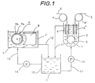
- Fig. 1 is schematic diagram illustrating means for carrying the method of the present invention.
- the method of the present invention employs an electrotinning tank containing electrotinning solution and an electrolytic tank containing electrotinning solution as electrolytic solution.
- An anode made of metallic tin is dissolved in the electrotinning solution of the electrolytic tank by the electrolysis.
- the tin dissolving period if the tin deposition rate onto a cathode is kept at a lower level than the metallic tin dissolving rate of anode by inducing the tin deposition reaction and the reducing reaction such as hydrogen generation on cathode, then the tin ion dissolved from the anode is efficiently supplied into the electrolytic solution without installing expensive diaphragm in between anode and cathode.
- the electrolytic solution containing the tin ion is supplied to the electrotinning tank.
- high quality tin plating layer is formed on the metallic material at an industrial scale economically and with a high current efficiency.
- the present invention is performed based on the above described findings. Accordingly, the procedure of the method of the present invention is described below.
- the electrolytic tank is prepared, which electrolytic tank contains the electrotinning solution as the electrolytic solution and is provided with the anode made of metallic tin and the cathode as the counter electrode against the anode.
- the electroplating tank is separately prepared, which electroplating tank includes the electrotinning solution and is provided with the insoluble anode and the metallic material to be placed into the plating solution. Direct current is applied between the insoluble anode and the metallic material which are placed in the electroplating tank to form the tin plating layer on the surface of the metallic material.
- Direct current is applied between the anode and the cathode which are placed in the electrolytic tank to dissolve the anode by electrolysis to generate tin ion, which tin ion then deposits on the cathode.
- Tin ion is supplied to the electrotinning solution in the electrolytic tank while controlling to keep the tin deposition rate on the cathode of the electrolytic tank at a lower level than the metallic tin dissolving rate of the anode of the electrolytic tank by inducing the tin deposition reaction and the reducing reaction of hydrogen generation on the cathode.
- the electrotinning solution supplied with the tin ion in the electrolytic tank is supplied to the electroplating solution in the electrotinning tank.
- the electrotinning solution in the electrolytic tank and the electroplating tank may be either acid or alkaline.
- the tin deposition rate on the cathode of the electrolytic tank is preferably controlled to at least 10% lower level than the metallic tin dissolving rate of the anode by inducing the tin deposition reaction and the reducing reaction of hydrogen generation on the cathode.
- the tin deposition rate on the cathode of the electrolytic tank is preferably controlled to at least 30% lower level than the metallic tin dissolving rate of the anode by inducing the tin deposition reaction and the reducing reaction of hydrogen generation on the cathode.
- the invention is described to a greater detail in the following embodiment using acid electrotinning solution as the electrotinning solution for both electrolytic tank and electroplating tank.
- the electrolytic tank is installed separately from the electrotinning tank to supply tin ion (Sn2+) to the plating solution in the electrotinning tank.
- the electrolytic tank is provided with the anode made of metallic tin and the cathode as the counter electrode. Direct current is applied between these electrodes, and the anode is dissolved by electrolysis.
- the dissolved anode portion provides the tin ion (Sn2+) to the electrolytic solution of electrotinning solution in the electrolytic tank.
- the electrolysis allows the high efficient dissolving of anode.
- the reducing reaction such as hydrogen generation occurs on the cathode to suppress the tin deposition on the cathode.
- Sn2+ tin ion supply to the electrolytic solution.
- the anode made of metallic tin in the electrolytic tank dissolves following eq.(1).
- a slight oxidation reaction such as oxygen generation on the surface of anode made of metallic tin collaterally occurs. Accordingly, SnO is generated on the surface of anode following eq.(2).
- the ratio of the current consumed by the reducing reaction such as hydrogen generation on the cathode to the electrolytic current becomes nearly equal to the supply efficiency of tin ion (Sn2+) to the electrolytic solution. Accordingly, the efficient supply of tin ion (Sn2+) to the electrolytic solution needs to enhance the reducing reaction such as hydrogen generation on the cathode to suppress the metallic tin deposition reaction on the surface of cathode as far as possible.
- the tin deposition rate on the cathode of electrolytic tank is preferably kept lower by at least 10% than the dissolving rate of the anode made of metallic tin.
- the difference is less than 10%, the supply of tin ion (Sn2+) to the electrolytic solution is insufficient and a large quantity of power is consumed to carry the electrolysis, which raises the power cost.
- the tin deposition rate on the cathode of electrolytic tank is kept lower by at least 30% than the dissolving rate of the anode made of metallic tin.
- the efficiency of the electrolytic current gets 100% and this is most advantageous in the operation cost. Therefore, it is most preferable that the tin deposition rate on the cathode of the electrolytic tank is 0%.
- a measure to reduce the tin deposition rate on the cathode below the dissolving rate of the anode made of metallic tin is to decrease the current efficiency for metallic tin deposition.
- Several means may be adopted to decrease the current efficiency for the tin deposition on cathode, which include increasing the electrolytic current density at cathode and reducing the temperature of electrolytic solution.
- the electrolytic current density on the cathode is about 50 A/dm2 so as to control the tin deposition rate on the cathode to be by 10% less than the dissolving rate of the anode made of metallic tin.
- the electrolytic current density on the cathode is about 70 A/dm2.
- an adequate electrolytic condition is selected to suppress oxidation reaction such as oxygen generation at the cathode as far as possible except for the tin dissolving reaction. That is to say, the electrolysis is carried out with a current density equal to the critical dissolving current density or less.
- the electrolytic current density is 30 A/dm2 or lower, the dissolution of substantially 100% is obtained. So far as the other operation conditions are concerned, higher the bath temperature, the better the operation is and the higher the stirring flow rate, the more effective the raising the dissolution efficiency is.
- the reducing reaction such as hydrogen generation at the cathode is enhanced by raising the electrolytic current density at the cathode higher than the level of electrolytic current density at the anode and by forming the concentration boundary layer of tin ion diffusion in the vicinity of cathode surface in the electrolytic solution during the electrolysis.
- the surface of cathode comprises a metallic sheet coated with a passive layer which is difficult to dissolve, which raises the current density at the actual electrolysis region.
- the surface of the cathode comprises alternative arrangement of conductive part and insulated parts.
- the cathode has a mesh structure, which decreases the total area of conductive part below the surface area of anode.
- the surface area of cathode is made smaller than that of anode by applying a configuration where a rod or wire cathode is surrounded by a cylindrical anode, for example.
- the metallic tin deposition on the cathode is removed from the cathode surface on occasion.
- the removed metallic tin is reused as the anode and is converted to tin ion.
- Examples of the electrolytic solution, or the acid electrotinning solution are acid electrotinning solution of sulfuric acid series such as ferrostannate bath, methane sulfonate bath, dimethyl sulfonate bath, and sulfuric acid bath, and acid electrotinning solution such as fluoborate bath and halide bath.
- sulfuric acid series such as ferrostannate bath, methane sulfonate bath, dimethyl sulfonate bath, and sulfuric acid bath
- acid electrotinning solution such as fluoborate bath and halide bath.
- tin ion (Sn2+) is supplied to the acid electrotinning solution by electrolysis, as described above. Consequently, there occurs no reverse effect as seen in the method of prior art (a), which reverse effect is the increase of dissolved oxygen in the plating solution and the SnO2 sludge formation in the plating solution during the process of chemical dissolving of metallic tin particles by the oxygen introduction.
- the reaction using a soluble anode is simply divided into the tin deposition in the tin plating process and the tin dissolving in the tin ion supplying process. Consequently, the additional reaction in the sulfuric acid series plating bath such as ferrostannate bath and methane sulfonate bath is basically the electrolytic reaction of water.
- the composition of electrolytic solution shows very little change during electrolysis.
- the method of the present invention needs no chemical, which chemical is necessary in the method of prior art (b) to form tin oxide such as SnO. In the halide bath, the electrolytic reaction of hydrochloric acid, etc.
- the method of the present invention does not require expensive diaphragm made of semipermeable membrane or ion-exchange membrane which is employed by the method of prior art (c) to separate anode from cathode to prevent the tin deposition on the cathode.
- the present invention is further described in greater detail in the following embodiment using alkaline electrotinning solution as the electrotinning solution for both electrolytic tank and electrotinning tank.
- the electrolytic tank is installed separately from the electrotinning tank to supply tin ion (Sn4+) to the plating solution in the electrotinning tank.
- the electrolytic tank is provided with the anode made of metallic tin and the cathode as the counter electrode. Direct current is applied between these electrodes, and the anode is dissolved by electrolysis.
- the dissolved anode portion provides the tin ion (Sn4+) to the electrolytic solution of electrotinning solution in the electrolytic tank.
- the electrolysis allows the high efficient dissolving of anode.
- the reducing reaction such as hydrogen generation occurs on the cathode to suppress the tin deposition on the cathode.
- the equivalent amount of tin ion (Sn4+) almost the same with the half equivalent amount of hydrogen generated on the cathode increases in the electrolytic solution.
- the ratio of the current consumed by the reducing reaction such as hydrogen generation on the cathode to the electrolytic current becomes nearly equal to the supply efficiency of tin ion (Sn4+) to the electrolytic solution. Accordingly, the efficient supply of tin ion (Sn4+) to the electrolytic solution needs to enhance the reducing reaction such as hydrogen generation on the cathode to suppress the metallic tin deposition reaction on the surface of cathode as far as possible.
- the tin deposition rate on the cathode of electrolytic tank is preferably kept lower by at least 30% than the dissolving rate of the anode made of metallic tin.
- the difference is less than 30%, the supply of tin ion (Sn4+) to the electrolytic solution is insufficient and a large quantity of power is consumed to carry the electrolysis, which raises the power cost.
- the tin deposition rate on the cathode of electrolytic tank is kept lower by at least 50% than the dissolving rate of the anode made of metallic tin. Since the efficiency of the electrolytic current gets 100%, this is most advantageous in the operation cost. Therefore, it is most preferable that the tin deposition rate on the cathode of the electrolytic tank is 0%.
- a measures to reduce the tin deposition rate on the cathode below the dissolving rate of the anode made of metallic tin is to decrease the current efficiency for metallic tin deposition.
- Several means may be adopted to decrease the current efficiency for the tin deposition on the cathode, which include increasing the electrolytic current density at cathode and reducing the temperature of electrolytic solution.
- the electrolytic current density on the cathode is about 3A/dm2 so as to control the tin deposition rate on the cathode to be by 30% less than the dissolving rate of the anode made of metallic tin.
- the electrolytic current density on the cathode is about 5A/dm2. Further, when a sodium bath is used, it is preferable that the electrolytic current density on the cathode is about 5.5 A/dm2 so as to control the tin deposition rate on the cathode to be by 30% less than the dissolving rate of the anode made of metallic tin. And so as to make 50% the difference between the tin deposition rate and the dissolving rate made of metallic tin, it is preferable that the electrolytic current density on the cathode is about 7.5 A/dm2.
- anode made of metallic tin it is preferable to maintain the high current efficiency for dissolving the anode.
- the reducing reaction such as hydrogen generation at the cathode is enhanced by raising the electrolytic current density at the cathode higher than the level of electrolytic current density at the anode and by forming the concentration boundary layer of tin ion diffusion in the vicinity of cathode surface in the electrolytic solution during the electrolysis.
- the surface of cathode comprises a metallic sheet coated with a passive layer which is difficult to dissolve, which raises the current density at the actual electrolysis region.
- the surface of cathode comprises alternative arrangement of conductive part and insulated part.
- the cathode has a screen structure, which decreases the total area of conductive part to below the surface area of anode.
- the surface area of cathode is made smaller than that of anode by applying a configuration where a rod or wire cathode is surrounded by a cylindrical anode, for example.
- the metallic tin deposition on the cathode is removed from the cathode surface on occasion.
- the removed metallic tin is re-used as the anode and is converted to tin ion (Sn4+).
- the electrolytic solution, or the alkaline electrotinning solution is a sodium bath or a potassium bath.
- tin ion (Sn4+) is supplied to the alkaline electrotinning solution by electrolysis, as described above. Consequently, there occurs no reverse effect as seen in the method of prior art (a), which reverse effect is the increase of dissolved oxygen in the plating solution and SnO2 sludge formation in the plating solution during the process of chemical dissolving of metallic tin particles by the oxygen introduction.
- the reaction using a soluble anode is simply divided into the tin deposition in the tin plating process and the tin dissolving in the tin ion supplying process. Consequently, the additional reaction is basically the electrolytic reaction of water in the alkaline plating bath such as sodium bath and potassium bath.
- the composition of electrolytic solution shows very little change during electrolysis.
- the method of the present invention needs no chemical, which chemical is necessary in the method of prior art (b) to form tin oxide such as SnO.
- the method of the present invention does not require expensive diaphragm made of semipermeable membrane or ion-exchange membrane which is employed by the method of prior art (c) to separate anode from cathode to prevent the tin deposition on the cathode.
- the reference character 1 illustrates the vertical electroplating tank containing acid electrotinning solution 2. Above the electrotinning tank 1, conductor rolls 4 and 4' are positioned at the inlet and outlet of the path of steel strip 3. At the bottom of the electrotinning tank 1, a sink roll 5 is located to turn the path of the steel strip 3 introduced into the electrotinning tank 1 from downward to upward direction. A pair of insoluble anodes 6 are placed to sandwich the steel strip 3 coming down from the conductor roll 4 to the sink roll 5. A pair of insoluble anodes 6' are placed to sandwich the steel strip 3 coming up to the roll 4'. Both insoluble anodes 6 and 6' are parallel to the steel strip 3, and the strip 3 passes through each pair of insoluble anodes 6 and 6' in the electrolytic tin plating solution 2.
- the reference character 7 illustrates the electrolytic tank to supply the electroplating solution to the electroplating tank.
- the electrolytic tank 7 is provided with a horizontal anode 8 made of metallic tin and having the designed length and a cathode 9 as the counter electrode against the anode 8.
- the cathode 9 has a cylindrical form having the similar length with the anode 8 and is rotatable around center axis thereof.
- the surface of cathode 9 is covered with the stainless steel part 9a and the resin part 9b.
- the surface of cathode 9 is formed in stripes having 1 mm width of stainless steel part 9a and 9mm width of resin part 9b alternatively along the circumference.
- the reference character 10 illustrates the re-circulation tank.
- the electrotinning solution conduits 11 and 11' connect the electrotinning tank 1 and the re-circulation tank 10.
- the electrotinning solution 2 in the re-circulation tank 10 is fed to the electrotinning tank 1 via the pump 13.
- the electroplating solution conduits 12 and 12' connect the electrolytic tank 7 and the re-circulation tank 10.
- the electrotinning solution 2 in the re-circulation tank 10 is fed to the electrolytic tank 7 via the pump 14.
- the electrotinning solution 2 is fed to the electrolytic tank 7 as the electrolytic solution.
- the cathode 9 rotates in arrowed direction. Direct current is applied between the anode 8 and the cathode 8 while the cathode 9 is rotating.
- the electrolytic current density on the cathode 9 becomes approximately 10 fold or more of the current density dissolving the anode 8 therewith.
- the reducing reaction such as hydrogen generation aggressively occurs.
- the difference amount of tin dissolved from the anode 8 and tin deposited on the cathode 9 is fed to the electroplating solution as tin ion.
- the metallic tin deposited on the surface of cathode 9 is removed by the knife installed near the cathode 9 (not shown in the figure) with the rotation of the cathode 9.
- the electrotinning solution 2 supplied with tin ion is introduced to the re-circulation tank 10 via the conduit 12' and is further fed to the electrotinning tank 1 from the re-circulation tank 10 through the conduit 11.
- the steel strip 3 continuously moves through each pair of 6 and 6' positioned in the electrotinning tank 1. While passing through the electrotinning tank 1, tin plating layer is formed on the surface of the steel strip 3.
- the electrotinning solution 2 overflowed from the electroltinning tank 1 returns to there-circulation tank 10 via the conduit 11', which solution 2 is further recycled to the electrolytic tank 7 from the re-circulation tank 10 via the conduit 12. In this way, the electrotinning solution 2 circulates among the electrolytic tank 7, recirculation tank 10, and electrotinning tank 1.
- the means illustrated in Fig. 1 was employed to carry out the tin electrolysis in the electrolytic tank 7 using an acid electrotinning solution with supplying tin ion (Sn2+) to the plating solution.
- the conditions of electrolysis are given in Table 1.
- the electrotinning solution supplied with tin ion (Sn2+) was supplied to the electrotinning tank 1.
- the tin plating layer was continuously formed on the surface of steel strip within the electrotinning tank 1.
- the tin ion supplying current efficiency was determined based on the assumption that the weight difference of tin determined by subtracting the weight of metallic tin deposited on the cathode from the weight reduction of the anode made of metallic tin was supplied to the tin plating solution as tin ion (Sn2+).
- the amount of tin ion supplying current efficiency which was determined agreed with the resulting increase of tin ion (Sn2+) in the plating solution determined by direct titration.
- the means illustrated in Fig. 1 was employed to carry out the tin electrolysis in the electrolytic tank 7 using an alkaline electrotinning solution with supplying tin ion (Sn4+) to the plating solution.
- the conditions of electrolysis are given in Table 2.
- the plating solution supplied with tin ion (Sn4+) was supplied to the electrotinning tank 1.
- the tin plating layer wascontinuously formed on the surface of steel strip within the electrotinning tank 1.
- the tin ion supplying current efficiency was determined based on the assumption that the weight difference of tin determined by subtracting the weight of metallic tin deposited on the cathode from the weight reduction of the anode made of metallic tin was supplied to the electroplating solution as tin ion (Sn4+).
- the amount of tin ion supplying current efficiency which was determined agreed with the resulting increase of tin ion (Sn4+) in the plating solution determined by the direct titration.
Landscapes
- Chemical & Material Sciences (AREA)
- Engineering & Computer Science (AREA)
- Chemical Kinetics & Catalysis (AREA)
- Electrochemistry (AREA)
- Materials Engineering (AREA)
- Metallurgy (AREA)
- Organic Chemistry (AREA)
- Automation & Control Theory (AREA)
- Electroplating And Plating Baths Therefor (AREA)
Description
- The present invention relates to a method of electrotinning of metallic material such as metal strip and metal wire, and particularly to a method of continuous electrotinning using an insoluble anode.
- A known method for continuous electrotinning of metallic material such as metal strip and metal wire in an electrotinning tank employs an insoluble anode, where the insoluble anode is immersed in electrotinning solution containing tin ion. An example of the insoluble anode is titanium coated with platinum. The tin plating layer is formed on the metallic material by applying direct current between the insoluble anode and the metal being plated while supplying tin ion (Sn²⁺) to the electrotinning solution.
- Such an electrotinning method using an insoluble anode maintains stable distance between anode and metallic material and keeps a constant current density level because the anode dissolves little, which provides a uniform coating weight throughout the tin plating layer formed on the metallic material and gives the tin layer having uniform surface gloss. In addition, no adjustment nor exchange of anode is required because the anode dissolves very little.
- A method of prior art (a) is proposed in JP-A-76735/74. JP-B-54079/81, and JP-B-54080/81 (the term "JP-A-" and "JP-B-" referred to herein signify "unexamined Japanese patent publication" and "examined Japanese patent publication", respectively). In the method (a), metallic tin particles are filled in a metallic tin dissolving tank which is installed separately from the electrotinning tank. By charging the plating solution containing dissolved oxygen into the metallic tin dissolving tank which is filled with the metallic tin particles, the metallic tin dissolves following the reaction given below to supply tin ion (Sn²⁺) to the plating solution.
Sn + 1/2O₂ + 2H⁺ → Sn²⁺ + H₂O
The plating solution supplied with tin ion (Sn²⁺) is fed to the plating solution in the electrotinning tank to electroplate the metallic material in the electrotinning tank. - The method of prior art (a) has, however, a problem. Since the plating solution contains a larger amount of dissolved oxygen, tin ion (Sn²⁺) in the plating solution is oxidized to yield SnO₂. The yielded SnO₂ does not dissolve and accumulates in the plating solution as fine sludge. The accumulated fine sludge adheres to the tin plating layer formed on the metallic material and the inside wall surface of the plating solution feed pipe to finally degrade the quality of tin plating and to plug the plating solution feed pipe.
- Another method of prior art (b) is presented in JP-A-41799/86 which describes a method of tin supply to electrotinning tank. In the method (b), tin ion is supplied to the plating solution by dissolving tin oxide such as SnO into the solution containing components to form the plating solution.
- The method (b) also has the disadvantage that the chemicals employed to yield tin oxide such as SnO are expensive and that these chemicals are likely to be contaminated, during the preparation stage, by impurities hazardous for tin plating.
- A further method of prior art (c) is presented in JP-A-70087/90 and JP-A-175894/90 which describe a method of electrotinning. In the method (c), the electrolytic tank which is installed separately from the electrotinning tank contains an anode made of metallic tin and a cathode as the counter electrode. These electrodes are separated each other by a diaphragm such as semipermeable membrane or ion-exchange membrane. By applying direct current between the anode and the cathode, tin ion generates from the metallic tin anode by electrolysis. The generated tin ion is introduced to the plating solution in the electrolytic tank while being prevented to deposit on the cathode by the presence of diaphragm. The prepared electrotinning solution containing tin ion is then fed to the plating solution in the electrotinning tank. The electroplating of the metallic material in the electrotinning tank is carried under the continuous supply of tin ion.
- The method (c), however, still has problems. The diaphragm such as semipermeable membrane and ion-exchange membrane separating the anode from the cathode is expensive, has poor strength and insufficient durability. In addition, the method operates at a low current efficiency owing to the limit of electrolytic current density, and consumes a large quantity of power because of the large reduction of electrolytic voltage across the diaphragm. As a result, the method (c) unavoidably raises the production cost and is difficult to commercialize on a large scale.
- The object of this invention is to provide a method of electrotinning to form a high quality tin plating layer on metallic material at an industrial scale economically and with a high current efficiency. To achieve the object, this invention provides the electrolytic tin plating method which comprises the following steps:
- (a) preparing an electrolytic tank containing electrotinning solution as electrolytic solution and being provided with an anode of metallic tin and a cathode as a counter electrode;
- (b) preparing an electroplating tank containing electrotinning solution and being provided with an insoluble anode and a metallic material to be supplied into the electrotinning solution;
- (c) applying direct current between the anode and the cathode which are placed in the electrolytic tank, the anode being dissolved by electrolysis to generate tin ion and the tin ion then depositing on the cathode;
- (d) controlling to keep a tin deposition rate onto the cathode in the electrolytic tank less than the metallic tin dissolving rate of the anode, the dissolved tin ion being fed to the electrotinning solution in the electrolytic tank;
- (e) supplying the electrotinning solution supplied with the tin ion at the electrolytic tank to the electrotinning solution in the electroplating tank; and
- (f) forming a tin plating layer on surface of the metallic material by applying the direct current between the insoluble anode and the metallic material which are placed in the electroplating tank.
- Fig. 1 is schematic diagram illustrating means for carrying the method of the present invention.
- The method of the present invention employs an electrotinning tank containing electrotinning solution and an electrolytic tank containing electrotinning solution as electrolytic solution. An anode made of metallic tin is dissolved in the electrotinning solution of the electrolytic tank by the electrolysis. During the tin dissolving period, if the tin deposition rate onto a cathode is kept at a lower level than the metallic tin dissolving rate of anode by inducing the tin deposition reaction and the reducing reaction such as hydrogen generation on cathode, then the tin ion dissolved from the anode is efficiently supplied into the electrolytic solution without installing expensive diaphragm in between anode and cathode. Thus the electrolytic solution containing the tin ion is supplied to the electrotinning tank. As a result, high quality tin plating layer is formed on the metallic material at an industrial scale economically and with a high current efficiency.
- The present invention is performed based on the above described findings. Accordingly, the procedure of the method of the present invention is described below.
- The electrolytic tank is prepared, which electrolytic tank contains the electrotinning solution as the electrolytic solution and is provided with the anode made of metallic tin and the cathode as the counter electrode against the anode. The electroplating tank is separately prepared, which electroplating tank includes the electrotinning solution and is provided with the insoluble anode and the metallic material to be placed into the plating solution. Direct current is applied between the insoluble anode and the metallic material which are placed in the electroplating tank to form the tin plating layer on the surface of the metallic material. Direct current is applied between the anode and the cathode which are placed in the electrolytic tank to dissolve the anode by electrolysis to generate tin ion, which tin ion then deposits on the cathode. Tin ion is supplied to the electrotinning solution in the electrolytic tank while controlling to keep the tin deposition rate on the cathode of the electrolytic tank at a lower level than the metallic tin dissolving rate of the anode of the electrolytic tank by inducing the tin deposition reaction and the reducing reaction of hydrogen generation on the cathode. The electrotinning solution supplied with the tin ion in the electrolytic tank is supplied to the electroplating solution in the electrotinning tank.
- The electrotinning solution in the electrolytic tank and the electroplating tank may be either acid or alkaline. In the case of acid electrotinning solution, the tin deposition rate on the cathode of the electrolytic tank is preferably controlled to at least 10% lower level than the metallic tin dissolving rate of the anode by inducing the tin deposition reaction and the reducing reaction of hydrogen generation on the cathode.
- For the case of alkaline electrotinning solution, the tin deposition rate on the cathode of the electrolytic tank is preferably controlled to at least 30% lower level than the metallic tin dissolving rate of the anode by inducing the tin deposition reaction and the reducing reaction of hydrogen generation on the cathode.
- The invention is described to a greater detail in the following embodiment using acid electrotinning solution as the electrotinning solution for both electrolytic tank and electroplating tank. The electrolytic tank is installed separately from the electrotinning tank to supply tin ion (Sn²⁺) to the plating solution in the electrotinning tank. The electrolytic tank is provided with the anode made of metallic tin and the cathode as the counter electrode. Direct current is applied between these electrodes, and the anode is dissolved by electrolysis. The dissolved anode portion provides the tin ion (Sn²⁺) to the electrolytic solution of electrotinning solution in the electrolytic tank. The electrolysis allows the high efficient dissolving of anode. On the other hand, the reducing reaction such as hydrogen generation occurs on the cathode to suppress the tin deposition on the cathode.
- The principle of tin ion (Sn²⁺) supply to the electrolytic solution is described below. The anode made of metallic tin in the electrolytic tank dissolves following eq.(1).
Sn → Sn²⁺ + 2e (1)
In addition, in the electrotinning solution of sulfuric acid series, for example, a slight oxidation reaction such as oxygen generation on the surface of anode made of metallic tin collaterally occurs. Accordingly, SnO is generated on the surface of anode following eq.(2).
2OH⁻ + Sn → O + Sn + H₂O + 2e → SnO + H₂O + 2e (2)
The generated SnO is converted to Sn²⁺ following eq.(3), which is then dissolved into the tin plating solution.
SnO + 2H₃O⁺ → Sn²⁺ + 3H₂O (3)
On the surface of cathode of the electrolytic tank, reactions at least expressed in eq.(4) and eq.(5) occur.
2H₃O⁺ + 2e → H₂ + 2H₂O (4)
Sn²⁺ + 2e → Sn (5)
The difference of the amount of tin between the tin dissolved from anode following the equations of (1), (2), and (3) and the tin deposited on cathode following eq.(5) is supplied to the electrolytic solution as tin ion (Sn²⁺). In other words, the equivalent amount of tin ion (Sn²⁺) which is almost the same with the equivalent amount of hydrogen generated on the cathode increases in the electrolytic solution. In concrete terms, the ratio of the current consumed by the reducing reaction such as hydrogen generation on the cathode to the electrolytic current becomes nearly equal to the supply efficiency of tin ion (Sn²⁺) to the electrolytic solution. Accordingly, the efficient supply of tin ion (Sn²⁺) to the electrolytic solution needs to enhance the reducing reaction such as hydrogen generation on the cathode to suppress the metallic tin deposition reaction on the surface of cathode as far as possible. - The tin deposition rate on the cathode of electrolytic tank is preferably kept lower by at least 10% than the dissolving rate of the anode made of metallic tin. When the difference is less than 10%, the supply of tin ion (Sn²⁺) to the electrolytic solution is insufficient and a large quantity of power is consumed to carry the electrolysis, which raises the power cost. More preferably, the tin deposition rate on the cathode of electrolytic tank is kept lower by at least 30% than the dissolving rate of the anode made of metallic tin. The efficiency of the electrolytic current gets 100% and this is most advantageous in the operation cost. Therefore, it is most preferable that the tin deposition rate on the cathode of the electrolytic tank is 0%.
- A measure to reduce the tin deposition rate on the cathode below the dissolving rate of the anode made of metallic tin is to decrease the current efficiency for metallic tin deposition. Several means may be adopted to decrease the current efficiency for the tin deposition on cathode, which include increasing the electrolytic current density at cathode and reducing the temperature of electrolytic solution. When a ferrostanate bath is used, it is preferable that the electrolytic current density on the cathode is about 50 A/dm² so as to control the tin deposition rate on the cathode to be by 10% less than the dissolving rate of the anode made of metallic tin. And so as to make 30% the difference between the tin deposition rate and the dissolving rate of the anode made of metallic tin, it is preferable that the electrolytic current density on the cathode is about 70 A/dm².
- To raise the dissolving efficiency of anode made of metallic tin, it is preferable to maintain the high current efficiency for dissolving the anode. When raising the current efficiency at the anode, an adequate electrolytic condition is selected to suppress oxidation reaction such as oxygen generation at the cathode as far as possible except for the tin dissolving reaction. That is to say, the electrolysis is carried out with a current density equal to the critical dissolving current density or less. In case of the ferrostanate bath, when the electrolytic current density is 30 A/dm² or lower, the dissolution of substantially 100% is obtained. So far as the other operation conditions are concerned, higher the bath temperature, the better the operation is and the higher the stirring flow rate, the more effective the raising the dissolution efficiency is.
- In order to reduce the tin deposition rate on the cathode in electrolytic tank lower by at least 10% than the tin dissolving rate of the anode made of metallic tin, the reducing reaction such as hydrogen generation at the cathode is enhanced by raising the electrolytic current density at the cathode higher than the level of electrolytic current density at the anode and by forming the concentration boundary layer of tin ion diffusion in the vicinity of cathode surface in the electrolytic solution during the electrolysis. Several modes of the method are given below.
- In the first mode, the surface of cathode comprises a metallic sheet coated with a passive layer which is difficult to dissolve, which raises the current density at the actual electrolysis region.
- In the second mode, the surface of the cathode comprises alternative arrangement of conductive part and insulated parts.
- In the third mode, the cathode has a mesh structure, which decreases the total area of conductive part below the surface area of anode.
- In the fourth mode, the surface area of cathode is made smaller than that of anode by applying a configuration where a rod or wire cathode is surrounded by a cylindrical anode, for example.
- The metallic tin deposition on the cathode is removed from the cathode surface on occasion. The removed metallic tin is reused as the anode and is converted to tin ion.
- Examples of the electrolytic solution, or the acid electrotinning solution, are acid electrotinning solution of sulfuric acid series such as ferrostannate bath, methane sulfonate bath, dimethyl sulfonate bath, and sulfuric acid bath, and acid electrotinning solution such as fluoborate bath and halide bath.
- According to the method of the present invention, tin ion (Sn²⁺) is supplied to the acid electrotinning solution by electrolysis, as described above. Consequently, there occurs no reverse effect as seen in the method of prior art (a), which reverse effect is the increase of dissolved oxygen in the plating solution and the SnO₂ sludge formation in the plating solution during the process of chemical dissolving of metallic tin particles by the oxygen introduction.
- In the method of the present invention, the reaction using a soluble anode is simply divided into the tin deposition in the tin plating process and the tin dissolving in the tin ion supplying process. Consequently, the additional reaction in the sulfuric acid series plating bath such as ferrostannate bath and methane sulfonate bath is basically the electrolytic reaction of water. The composition of electrolytic solution shows very little change during electrolysis. The method of the present invention needs no chemical, which chemical is necessary in the method of prior art (b) to form tin oxide such as SnO. In the halide bath, the electrolytic reaction of hydrochloric acid, etc. is added, so the supply of chlorine and other substances is needed, which chlorine and other substances are generated from the insoluble anode in the plating process and are emitted to outside of the system without caught by the plating solution. Nevertheless, according to the method of the present invention, the supply of such chlorine and other substances is carried easily and inexpensively.
- Furthermore, the method of the present invention does not require expensive diaphragm made of semipermeable membrane or ion-exchange membrane which is employed by the method of prior art (c) to separate anode from cathode to prevent the tin deposition on the cathode.
- The present invention is further described in greater detail in the following embodiment using alkaline electrotinning solution as the electrotinning solution for both electrolytic tank and electrotinning tank. The electrolytic tank is installed separately from the electrotinning tank to supply tin ion (Sn⁴⁺) to the plating solution in the electrotinning tank. The electrolytic tank is provided with the anode made of metallic tin and the cathode as the counter electrode. Direct current is applied between these electrodes, and the anode is dissolved by electrolysis. The dissolved anode portion provides the tin ion (Sn⁴⁺) to the electrolytic solution of electrotinning solution in the electrolytic tank. The electrolysis allows the high efficient dissolving of anode. On the other hand, the reducing reaction such as hydrogen generation occurs on the cathode to suppress the tin deposition on the cathode.
- The principle of tin ion (Sn⁴⁺) supply to the electrolytic solution is described below. The anode made of metallic tin in the electrolytic tank dissolves following eq.(6).
Sn → Sn⁴⁺ + 2e (6)
On the surface of cathode of the electrolytic tank, reactions at least expressed in eq.(7) and eq.(8) occur.
2H₃O⁺ + 2e → H₂ + 2H₂O (7)
Sn⁴⁺ + 4e → Sn (8)
The difference of the amount of tin between the tin dissolved from anode following eq.(6), and the tin deposited on cathode following eq.(8) is supplied to the electrolytic solution as tin ion (Sn⁴⁺). In other words, the equivalent amount of tin ion (Sn⁴⁺) almost the same with the half equivalent amount of hydrogen generated on the cathode increases in the electrolytic solution. In concrete terms, the ratio of the current consumed by the reducing reaction such as hydrogen generation on the cathode to the electrolytic current becomes nearly equal to the supply efficiency of tin ion (Sn⁴⁺) to the electrolytic solution. Accordingly, the efficient supply of tin ion (Sn⁴⁺) to the electrolytic solution needs to enhance the reducing reaction such as hydrogen generation on the cathode to suppress the metallic tin deposition reaction on the surface of cathode as far as possible. - The tin deposition rate on the cathode of electrolytic tank is preferably kept lower by at least 30% than the dissolving rate of the anode made of metallic tin. When the difference is less than 30%, the supply of tin ion (Sn⁴⁺) to the electrolytic solution is insufficient and a large quantity of power is consumed to carry the electrolysis, which raises the power cost. More preferably, the tin deposition rate on the cathode of electrolytic tank is kept lower by at least 50% than the dissolving rate of the anode made of metallic tin. Since the efficiency of the electrolytic current gets 100%, this is most advantageous in the operation cost. Therefore, it is most preferable that the tin deposition rate on the cathode of the electrolytic tank is 0%.
- A measures to reduce the tin deposition rate on the cathode below the dissolving rate of the anode made of metallic tin is to decrease the current efficiency for metallic tin deposition. Several means may be adopted to decrease the current efficiency for the tin deposition on the cathode, which include increasing the electrolytic current density at cathode and reducing the temperature of electrolytic solution. When a sodium bath is used, it is preferable that the electrolytic current density on the cathode is about 3A/dm² so as to control the tin deposition rate on the cathode to be by 30% less than the dissolving rate of the anode made of metallic tin. And so as to make 50% the difference between the tin deposition rate and the dissolving rate of the anode made of metallic tin, it is preferable that the electrolytic current density on the cathode is about 5A/dm². Further, when a sodium bath is used, it is preferable that the electrolytic current density on the cathode is about 5.5 A/dm² so as to control the tin deposition rate on the cathode to be by 30% less than the dissolving rate of the anode made of metallic tin. And so as to make 50% the difference between the tin deposition rate and the dissolving rate made of metallic tin, it is preferable that the electrolytic current density on the cathode is about 7.5 A/dm².
- To raise the dissolving efficiency of anode made of metallic tin, it is preferable to maintain the high current efficiency for dissolving the anode. To improve the current efficiency of the anode, it is preferable to maintain the anode current density at below the critical current density and in a range not diminishing the greenish yellow coating film on the anode.
- In order to reduce the tin deposition rate on the cathode in electrolytic tank lower by at least 30% than the tin dissolving rate of the anode made of metallic tin, the reducing reaction such as hydrogen generation at the cathode is enhanced by raising the electrolytic current density at the cathode higher than the level of electrolytic current density at the anode and by forming the concentration boundary layer of tin ion diffusion in the vicinity of cathode surface in the electrolytic solution during the electrolysis. Several modes of the method are given below.
- In the first mode, the surface of cathode comprises a metallic sheet coated with a passive layer which is difficult to dissolve, which raises the current density at the actual electrolysis region.
- In the second mode, the surface of cathode comprises alternative arrangement of conductive part and insulated part.
- In the third mode, the cathode has a screen structure, which decreases the total area of conductive part to below the surface area of anode.
- In the fourth mode, the surface area of cathode is made smaller than that of anode by applying a configuration where a rod or wire cathode is surrounded by a cylindrical anode, for example.
- The metallic tin deposition on the cathode is removed from the cathode surface on occasion. The removed metallic tin is re-used as the anode and is converted to tin ion (Sn⁴⁺).
- The electrolytic solution, or the alkaline electrotinning solution, is a sodium bath or a potassium bath. According to the method of the present invention, tin ion (Sn⁴⁺) is supplied to the alkaline electrotinning solution by electrolysis, as described above. Consequently, there occurs no reverse effect as seen in the method of prior art (a), which reverse effect is the increase of dissolved oxygen in the plating solution and SnO₂ sludge formation in the plating solution during the process of chemical dissolving of metallic tin particles by the oxygen introduction.
- In the method of the present invention, the reaction using a soluble anode is simply divided into the tin deposition in the tin plating process and the tin dissolving in the tin ion supplying process. Consequently, the additional reaction is basically the electrolytic reaction of water in the alkaline plating bath such as sodium bath and potassium bath. The composition of electrolytic solution shows very little change during electrolysis. The method of the present invention needs no chemical, which chemical is necessary in the method of prior art (b) to form tin oxide such as SnO. Furthermore, the method of the present invention does not require expensive diaphragm made of semipermeable membrane or ion-exchange membrane which is employed by the method of prior art (c) to separate anode from cathode to prevent the tin deposition on the cathode.
- Processing therefore to describe the present invention in detail, reference should be made to Fig. 1. The
reference character 1 illustrates the vertical electroplating tank containingacid electrotinning solution 2. Above theelectrotinning tank 1, conductor rolls 4 and 4' are positioned at the inlet and outlet of the path ofsteel strip 3. At the bottom of theelectrotinning tank 1, asink roll 5 is located to turn the path of thesteel strip 3 introduced into theelectrotinning tank 1 from downward to upward direction. A pair ofinsoluble anodes 6 are placed to sandwich thesteel strip 3 coming down from theconductor roll 4 to thesink roll 5. A pair of insoluble anodes 6' are placed to sandwich thesteel strip 3 coming up to the roll 4'. Bothinsoluble anodes 6 and 6' are parallel to thesteel strip 3, and thestrip 3 passes through each pair ofinsoluble anodes 6 and 6' in the electrolytictin plating solution 2. - The
reference character 7 illustrates the electrolytic tank to supply the electroplating solution to the electroplating tank. Theelectrolytic tank 7 is provided with ahorizontal anode 8 made of metallic tin and having the designed length and acathode 9 as the counter electrode against theanode 8. Thecathode 9 has a cylindrical form having the similar length with theanode 8 and is rotatable around center axis thereof. The surface ofcathode 9 is covered with thestainless steel part 9a and theresin part 9b. For example, the surface ofcathode 9 is formed in stripes having 1 mm width ofstainless steel part 9a and 9mm width ofresin part 9b alternatively along the circumference. - The
reference character 10 illustrates the re-circulation tank. Theelectrotinning solution conduits 11 and 11' connect theelectrotinning tank 1 and there-circulation tank 10. Theelectrotinning solution 2 in there-circulation tank 10 is fed to theelectrotinning tank 1 via thepump 13. Theelectroplating solution conduits 12 and 12' connect theelectrolytic tank 7 and there-circulation tank 10. Theelectrotinning solution 2 in there-circulation tank 10 is fed to theelectrolytic tank 7 via thepump 14. - The
electrotinning solution 2 is fed to theelectrolytic tank 7 as the electrolytic solution. Thecathode 9 rotates in arrowed direction. Direct current is applied between theanode 8 and thecathode 8 while thecathode 9 is rotating. The electrolytic current density on thecathode 9 becomes approximately 10 fold or more of the current density dissolving theanode 8 therewith. On thecathode 9, the reducing reaction such as hydrogen generation aggressively occurs. The difference amount of tin dissolved from theanode 8 and tin deposited on thecathode 9 is fed to the electroplating solution as tin ion. The metallic tin deposited on the surface ofcathode 9 is removed by the knife installed near the cathode 9 (not shown in the figure) with the rotation of thecathode 9. - The
electrotinning solution 2 supplied with tin ion is introduced to there-circulation tank 10 via the conduit 12' and is further fed to theelectrotinning tank 1 from there-circulation tank 10 through theconduit 11. Thesteel strip 3 continuously moves through each pair of 6 and 6' positioned in theelectrotinning tank 1. While passing through theelectrotinning tank 1, tin plating layer is formed on the surface of thesteel strip 3. Theelectrotinning solution 2 overflowed from theelectroltinning tank 1 returns to there-circulation tank 10 via the conduit 11', whichsolution 2 is further recycled to theelectrolytic tank 7 from there-circulation tank 10 via theconduit 12. In this way, theelectrotinning solution 2 circulates among theelectrolytic tank 7,recirculation tank 10, andelectrotinning tank 1. - The means illustrated in Fig. 1 was employed to carry out the tin electrolysis in the
electrolytic tank 7 using an acid electrotinning solution with supplying tin ion (Sn²⁺) to the plating solution. The conditions of electrolysis are given in Table 1. The electrotinning solution supplied with tin ion (Sn²⁺) was supplied to theelectrotinning tank 1. The tin plating layer was continuously formed on the surface of steel strip within theelectrotinning tank 1. The tin ion supplying current efficiency was determined based on the assumption that the weight difference of tin determined by subtracting the weight of metallic tin deposited on the cathode from the weight reduction of the anode made of metallic tin was supplied to the tin plating solution as tin ion (Sn²⁺). The amount of tin ion supplying current efficiency which was determined agreed with the resulting increase of tin ion (Sn²⁺) in the plating solution determined by direct titration. - The means illustrated in Fig. 1 was employed to carry out the tin electrolysis in the
electrolytic tank 7 using an alkaline electrotinning solution with supplying tin ion (Sn⁴⁺) to the plating solution. The conditions of electrolysis are given in Table 2. The plating solution supplied with tin ion (Sn⁴⁺) was supplied to theelectrotinning tank 1. The tin plating layer wascontinuously formed on the surface of steel strip within theelectrotinning tank 1. The tin ion supplying current efficiency was determined based on the assumption that the weight difference of tin determined by subtracting the weight of metallic tin deposited on the cathode from the weight reduction of the anode made of metallic tin was supplied to the electroplating solution as tin ion (Sn⁴⁺). The amount of tin ion supplying current efficiency which was determined agreed with the resulting increase of tin ion (Sn⁴⁺) in the plating solution determined by the direct titration.Table 1 Plating solution Temperature of plating solution (°C) Anode dissolving current density (A/dm²) Tin ion supplying current efficiency (%) Sulfuric acid bath 30 30 80 Ferrostannate bath 40 20 71 Methane sulfonate bath 35 40 62 Cresol sulfonate bath 20 10 55 Halide (chlorinated) bath 65 50 69 Fluosilicate bath 30 15 78 Fluoborate bath 35 40 65 Table 2 Plating solution Temperature of plating solution (°C) Anode dissolving current density (A/dm²) Tin ion supplying current efficiency (%) Potassium bath 65 8 86 Potassium bath 75 8 82 Potassium bath 85 8 79 Potassium bath 85 10 85 Sodium bath 65 5 81 Sodium bath 75 5 85 Sodium bath 85 7 88
Claims (12)
- A method of electrotinning comprising the steps of:(a) preparing an electrolytic tank (7) containing electrotinning solution (2) as electrolytic solution and being provided with an anode (8) made of metallic tin and a cathode (9) as a counter electrode against said anode;(b) preparing an electroplating tank (1) containing electrotinning solution (2) and being provided with an insoluble anode (6), (6') and a metallic material (3) to be placed into said electrotinning solution;(c) forming a tin plating layer on surface of said metallic material by applying direct current between said insoluble anode and said metallic material both being placed in said electroplating tank;(d) applying direct current between said anode and said cathode both being placed in said electrolytic tank, said anode being dissolved by electrolysis to generate tin ion to deposit on said cathode;(e) controlling a tin deposition rate onto said cathode of said electrolytic tank to keep lower than the metallic tin dissolving rate of said anode, the dissolved tin ion being fed to said electrotinning solution in said electrolytic tank by suppressing a tin deposition reaction and by enhancing a reducing reaction of hydrogen generation on said cathode; and(f) supplying said electrotinning solution supplied with the tin ion at said electrolytic tank to said electrotinning solution in said electroplating tank.
- The method of electrotinning of claim 1, characterized in that:
said electrotinning solution in both said electrolytic tank and said electrotinning tank is an acid electrotinning solution; and
the tin deposition rate on said cathode of said electrolytic tank is controlled to be lower by at least 10% than the metallic tin dissolving rate of said anode by suppressing the tin deposition reaction and by enhancing the reducing reaction of hydrogen generation on said cathode. - The method of electrotinning of claim 2, characterized in that the tin deposition rate on said cathode of said electrolytic tank is controlled to be lower by at least 30% than the metallic tin dissolving rate of said anode.
- The method of electrotinning of claim 2, characterized in that said acid electrotinning solution is a bath selected from the group of sulfuric acid bath, ferrostannate bath, methane sulfonate bath, cresol sulfonate bath, halide bath, fluosilicate bath, and fluoborate bath.
- The method of electrotinning of claim 1, characterized in that
said electrotinning solution in both said electrolytic tank and said electrotinning tank is an alkaline electrotinning solution; and
the tin deposition rate on said cathode of said electrolytic tank is controlled to be lower by at least 30% than the metallic tin dissolving rate of said anode by suppressing the tin deposition reaction and by enhancing the reducing reaction of hydrogen generation on said cathode. - The method of electrotinning of claim 5, characterized in that the tin deposition rate on said cathode of said electrolytic tank is controlled to be lower by at least 50% than the metallic tin dissolving rate of said anode.
- The method of electrotinning of claim 5, characterized in that said alkaline electrotinning solution is a sodium bath or a potassium bath.
- The method of electrotinning of claim 1, characterized in that the controlling of the tin deposition rate on said cathode of said electrolytic tank includes controlling by raising the electrolytic current density of said cathode above the electrolytic current density of said anode made of metallic tin.
- The method of electrotinning of claim 8, characterized in that the tin deposition rate on said cathode is controlled by using a cathode comprising a metallic plate being covered with a passive layer.
- The method of electrotinning of claim 8, characterized in that the tin deposition rate on said cathode is controlled by using a cathode having a surface structure comprising a conductive part and a insulating part.
- The method of electrotinning of claim 8, characterized in that the tin deposition rate on said cathode is controlled by making the conductive part area of said cathode smaller than the surface area of said anode by using a cathode comprising a mesh structure.
- The method of electrotinning of claim 8, characterized in that the tin deposition rate on said cathode is controlled by making the surface area of said cathode smaller than the surface area of said anode by means of arranging said anode to surround said cathode.
Applications Claiming Priority (4)
| Application Number | Priority Date | Filing Date | Title |
|---|---|---|---|
| JP36008191A JPH05179498A (en) | 1991-12-26 | 1991-12-26 | Electric tin plating method for metallic material |
| JP3360080A JPH05179497A (en) | 1991-12-26 | 1991-12-26 | Electric tin plating method for metallic material |
| JP360081/91 | 1991-12-26 | ||
| JP360080/91 | 1991-12-26 |
Publications (2)
| Publication Number | Publication Date |
|---|---|
| EP0550002A1 EP0550002A1 (en) | 1993-07-07 |
| EP0550002B1 true EP0550002B1 (en) | 1995-09-06 |
Family
ID=26581073
Family Applications (1)
| Application Number | Title | Priority Date | Filing Date |
|---|---|---|---|
| EP19920121830 Expired - Lifetime EP0550002B1 (en) | 1991-12-26 | 1992-12-22 | Method of electrotinning |
Country Status (2)
| Country | Link |
|---|---|
| EP (1) | EP0550002B1 (en) |
| DE (1) | DE69204644T2 (en) |
Cited By (1)
| Publication number | Priority date | Publication date | Assignee | Title |
|---|---|---|---|---|
| US7931760B2 (en) | 2006-03-02 | 2011-04-26 | Fujitsu Limited | Whiskerless plated structure and plating method |
Families Citing this family (4)
| Publication number | Priority date | Publication date | Assignee | Title |
|---|---|---|---|---|
| EP1085111A1 (en) * | 1999-09-13 | 2001-03-21 | Ulisses Brandao | A replenishment process for metal electrodeposition baths |
| EP1207219A1 (en) * | 2000-11-20 | 2002-05-22 | PIRELLI PNEUMATICI S.p.A. | Equipment and method for covering a metallic element with a layer of copper |
| GB2383337A (en) * | 2001-12-21 | 2003-06-25 | Accentus Plc | Electroplating plant and method |
| CN112111762A (en) * | 2020-09-26 | 2020-12-22 | 深圳市海里表面技术处理有限公司 | High-finish material belt tinning process and material belt manufactured by same |
Family Cites Families (2)
| Publication number | Priority date | Publication date | Assignee | Title |
|---|---|---|---|---|
| GB569447A (en) * | 1943-03-19 | 1945-05-24 | Metal & Thermit Corp | Improvement in process of tin electroplating |
| NL8602730A (en) * | 1986-10-30 | 1988-05-16 | Hoogovens Groep Bv | METHOD FOR ELECTROLYTIC TINNING TIN USING AN INSOLUBLE ANODE. |
-
1992
- 1992-12-22 EP EP19920121830 patent/EP0550002B1/en not_active Expired - Lifetime
- 1992-12-22 DE DE1992604644 patent/DE69204644T2/en not_active Expired - Fee Related
Cited By (1)
| Publication number | Priority date | Publication date | Assignee | Title |
|---|---|---|---|---|
| US7931760B2 (en) | 2006-03-02 | 2011-04-26 | Fujitsu Limited | Whiskerless plated structure and plating method |
Also Published As
| Publication number | Publication date |
|---|---|
| DE69204644D1 (en) | 1995-10-12 |
| DE69204644T2 (en) | 1996-03-21 |
| EP0550002A1 (en) | 1993-07-07 |
Similar Documents
| Publication | Publication Date | Title |
|---|---|---|
| US5162079A (en) | Process and apparatus for control of electroplating bath composition | |
| EP0268823B1 (en) | Method of electrolytic tinning using an insoluble anode | |
| US6251255B1 (en) | Apparatus and method for electroplating tin with insoluble anodes | |
| KR100954069B1 (en) | Concentrating bath by anode dissolution of metal, electroplating apparatus for metal comprising same and electroplating method using same | |
| US4521281A (en) | Process and apparatus for continuously producing multivalent metals | |
| US5516414A (en) | Method and apparatus for electrolytically plating copper | |
| KR20010024470A (en) | Copper metallization of silicon wafers using insoluble anodes | |
| US20160024683A1 (en) | Apparatus and method for electrolytic deposition of metal layers on workpieces | |
| US4555317A (en) | Cathode for the electrolytic production of hydrogen and its use | |
| CA1256819A (en) | Process for reconditioning a used ammoniacal copper etching solution containing copper solute | |
| US5082538A (en) | Process for replenishing metals in aqueous electrolyte solutions | |
| US4906340A (en) | Process for electroplating metals | |
| EP0550002B1 (en) | Method of electrotinning | |
| US5705048A (en) | Apparatus and a process for regenerating a CUCl2 etchant | |
| US4936965A (en) | Method for continuously electro-tinplating metallic material | |
| USRE34191E (en) | Process for electroplating metals | |
| PL95746B1 (en) | METHOD OF GALVANIC TINNING | |
| JPH10511743A (en) | Plating equipment | |
| JPH05302199A (en) | Method for controlling composition of copper plating bath in copper plating using insoluble anode | |
| EP0501548A1 (en) | Method of making iron foil by electrodeposition | |
| WO2001092604A2 (en) | Electrolysis cell for restoring the concentration of metal ions in processes of electroplating | |
| US6569311B2 (en) | Continuous electrochemical process for preparation of zinc powder | |
| KR20230173685A (en) | Coating device and coating method for coating components or semi-finished products with a chrome layer | |
| US6569310B2 (en) | Electrochemical process for preparation of zinc powder | |
| JPH05179497A (en) | Electric tin plating method for metallic material |
Legal Events
| Date | Code | Title | Description |
|---|---|---|---|
| PUAI | Public reference made under article 153(3) epc to a published international application that has entered the european phase |
Free format text: ORIGINAL CODE: 0009012 |
|
| 17P | Request for examination filed |
Effective date: 19921222 |
|
| AK | Designated contracting states |
Kind code of ref document: A1 Designated state(s): DE GB |
|
| 17Q | First examination report despatched |
Effective date: 19941107 |
|
| GRAA | (expected) grant |
Free format text: ORIGINAL CODE: 0009210 |
|
| AK | Designated contracting states |
Kind code of ref document: B1 Designated state(s): DE GB |
|
| REF | Corresponds to: |
Ref document number: 69204644 Country of ref document: DE Date of ref document: 19951012 |
|
| PLBE | No opposition filed within time limit |
Free format text: ORIGINAL CODE: 0009261 |
|
| STAA | Information on the status of an ep patent application or granted ep patent |
Free format text: STATUS: NO OPPOSITION FILED WITHIN TIME LIMIT |
|
| 26N | No opposition filed | ||
| PGFP | Annual fee paid to national office [announced via postgrant information from national office to epo] |
Ref country code: GB Payment date: 19971215 Year of fee payment: 6 |
|
| PGFP | Annual fee paid to national office [announced via postgrant information from national office to epo] |
Ref country code: DE Payment date: 19971230 Year of fee payment: 6 |
|
| PG25 | Lapsed in a contracting state [announced via postgrant information from national office to epo] |
Ref country code: GB Free format text: LAPSE BECAUSE OF NON-PAYMENT OF DUE FEES Effective date: 19981222 |
|
| GBPC | Gb: european patent ceased through non-payment of renewal fee |
Effective date: 19981222 |
|
| PG25 | Lapsed in a contracting state [announced via postgrant information from national office to epo] |
Ref country code: DE Free format text: LAPSE BECAUSE OF NON-PAYMENT OF DUE FEES Effective date: 19991001 |